


Carbon content in steel has a direct correlation to the hardness and overall strength of a component after heat treatment. Carbon can take many forms in the steel alloy, but during austenization, generally the goal is to place all available carbon into the austenitic solid solution.
Three main factors affect the amount of carbon entering into solid solution: 1) The form of carbon at room temperature, 2) The heating rate from room temperature to the austenitizing temperature, and 3) The soaking time at high temperature. In order to understand whether the requisite amount of carbon has entered the austenite matrix, hardness testing would need to be performed on samples processed at different heating rates and soaking times. This type of evaluation can be expensive and time consuming. A simpler way to ensure all carbon has entered the austenite matrix is to use heat-treatment simulation software, such as DANTE, to evaluate the effects of different parameters quickly and cost effectively.
Of course, this requires accurate material data, and simulation can help dramatically reduce the amount of physical testing required after the material data is known. DANTE provides a material database with many common steel grades already characterized.
DANTE Solutions has developed a material simulation software tool, called Mat_Simulator, that uses the DANTE material models and material database to predict phase transformations, strain, hardness, carbon dissolved in austenite, and carbon in carbides from heating and cooling schedules provided by the user. It is a powerful tool that can be used to evaluate a material’s response to defined temperature changes. These heating and cooling rates are representative of different locations through a component’s cross-sectional thickness. Mat_Simulator is used in the following discussion to show the effects of different parameters on the amount of carbon in austenite at the time quenching begins when carbides are present in the material. The material examined has a total carbon content of 0.8 percent.
As previously mentioned, carbon can take on many forms in a steel alloy. It can take on the form of cementite layers of varying thickness in pearlite, spheroidal carbides from thermal processing, carbides from a carburizing process, etc.
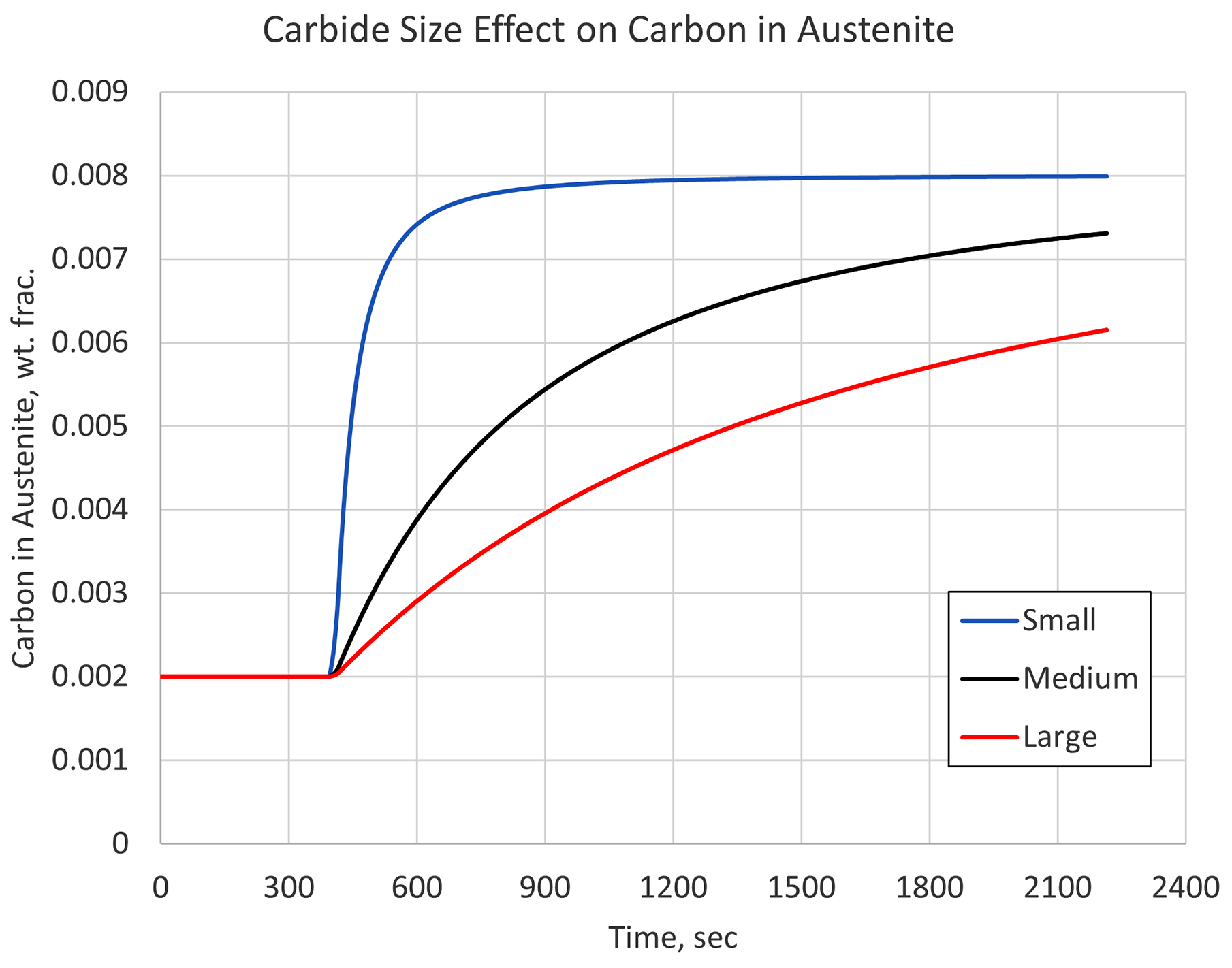
Carbides come in many shapes and forms, with some dissolving more quickly than others. Understanding the initial microstructure is important if a proper austenitizing cycle is to be determined. Figure 1 shows the carbon simulation results in austenite for three different carbide sizes, given an identical heating rate, austenitizing temperature, and processing time. A quenching step would immediately follow this austenitizing step.
Figure 1 makes it clear that the size of the carbides can have a significant effect on the material’s hardenability by limiting the amount of carbon available in the austenite matrix at the start of quenching. In this example, any section of a component with large carbides and exposed to the relative slow heating rate used, would behave as though it contained 0.6 percent carbon, not the 0.8 percent that is stated as the carbon content.
So, even though standards are in place for holding times with respect to cross-sectional thickness, it is still important to understand the initial microstructure of the material being heat treated. Once characterized, the initial microstructure can be used in conjunction with simulation to determine optimum heating cycles for a given component.
A faster heating rate will require a longer soak time to allow carbon to enter into solid solution for the same part cross-sectional thickness. There are two reasons for this: First, a faster heating rate delays the austenite transformation (the Ac3 temperature is effectively raised) and carbon does not begin to efficiently enter solid-state solution until the material has transformed to austenite. Second, a faster heating rate means less time above the Ac3 temperature, meaning the carbon has less time to enter the solution before reaching the target hold temperature.
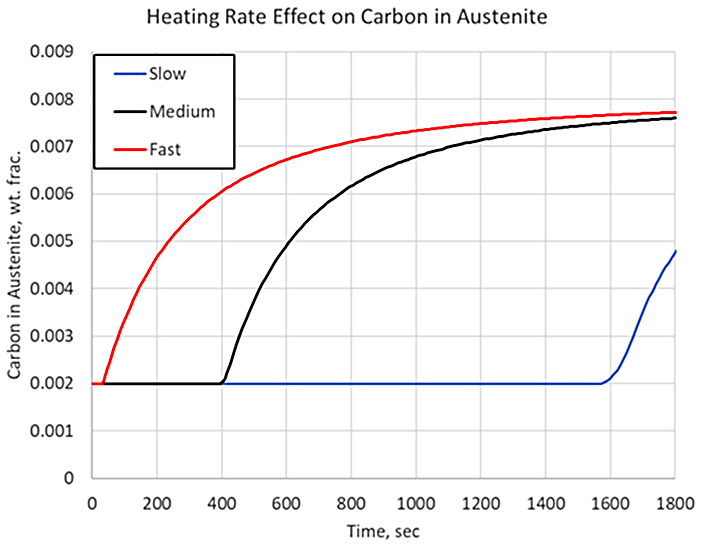
Figure 2 shows the carbon in carbide form for three heating rates, representing various cross-sectional thicknesses, given identical carbide size, austenitizing temperature, and processing time. The slower the heating rate, the longer it takes for the carbide to begin to dissolve. Given identical parameters of carbide size, austenitizing temperatures, and hold times, there would be no difference in the amount of carbon dissolved. However, where heating rates begin to play a significant role is when the holding time is not designed properly for the center of the part, and processing times are kept constant between various geometries. If a larger-than-normal cross-section is treated, then the holding time must be adjusted accordingly because of the decreased heating rate at the core of the component. For example, if the total processing time from the fast heating rate is used on a cross-section that experiences the slow cooling rate at its core, the surface of the component would act like a material with 0.8 percent carbon, but the core would act like a material with 0.5 percent carbon, with respect to hardenability, as shown in Figure 2.
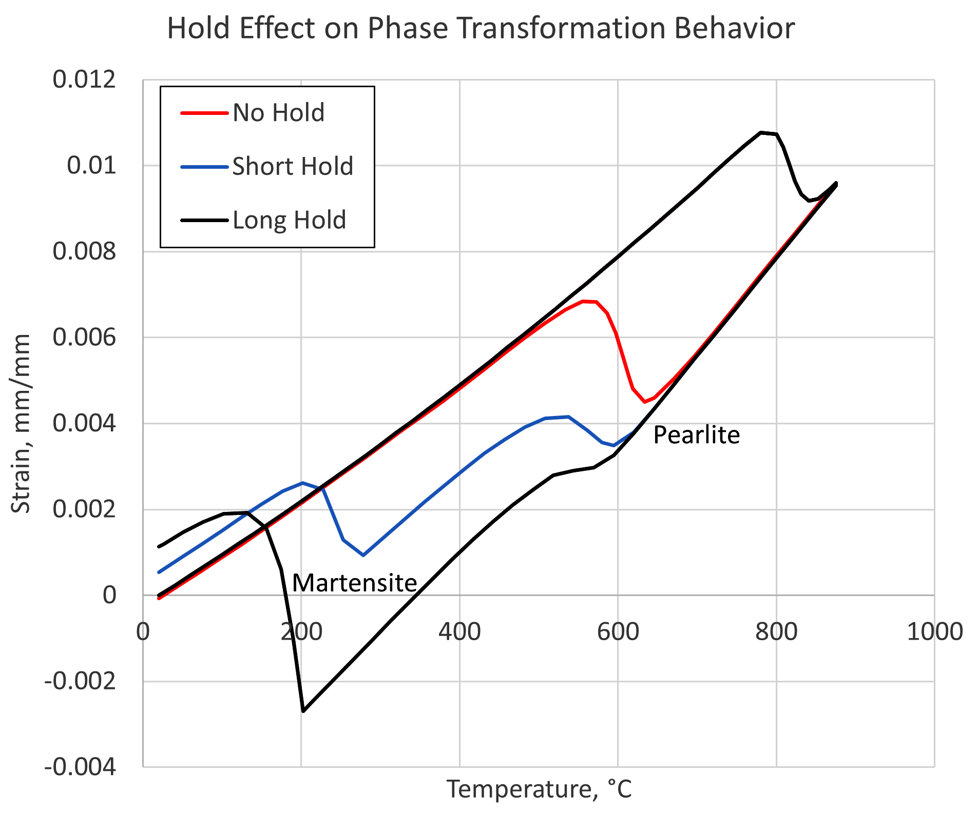
For a process with the aim of transforming a particular steel alloy to a known microstructure, the amount of carbon in the austenite solution can have a significant effect on the phases obtained. Figure 3 shows simulation results of strain vs. temperature for a steel containing 0.8 percent carbon, assuming medium-sized carbides. The simulation also assumes a medium heating rate and a fast quenching rate. Three holding times are then examined for their effect on the phases obtained after quenching. The length of time the material is held at the austenitizing temperature determines the amount of carbon that is able to dissolve into the austenite matrix, which in turn affects the hardenability of the material.
As can be seen in Figure 3, the situation in which the material was quenched immediately upon reaching the austenitizing temperature, labeled “No Hold,” results in a microstructure of 100-percent pearlite. The short hold time results in a mixed structure of pearlite and martensite, whereas the long hold time contains a microstructure consisting of mostly martensite with a small amount of pearlite. The temperatures of the phases are shifted slightly due to the different amounts of carbon present in austenite at the time of quenching.
Holding times can have a significant impact on short time processes, such as induction heating. While the goal is high throughput, it is critical to ensure there is enough time for the carbides to dissolve. This is particularly important for subsurface material that may have a slower heating rate due to the reduced Joule heating occurring at that location and being dependent to some extent on thermal conduction to increase the temperature. Simulation can also be a powerful tool when examining an induction-hardening process.
In conclusion, it has been shown through simulation that the effect of carbide size, heating rates, and holding times during austenitization have a significant effect on the amount of carbon that can enter the austenite matrix before quenching. The carbon in austenite has a significant effect on the hardenability of the material and must be considered when designing austenitization cycles. It has also been shown that heat-treatment simulation software, such as DANTE, can be used to successfully evaluate and design heating cycles to ensure all carbides have dissolved and the material will behave as expected.


 general practice for CQI-9 and AMS2750E")


