


Gear design is a complex process, involving dozens of parameters, tolerances, and relationships to mating components. Generally, professional standards guide the gear designer to the appropriate gear dimensions, given mating and loading requirements. [1-2] After heat-treatment, gears are inspected using a slew of methods, depending on the particular gear geometry and critical locations of interest. [3-5] Heat treatment simulation provides a cheaper and faster alternative to physical testing but is lacking capabilities to relate the predicted distortion back to gear measurements made on the shop floor or in the metallurgical lab. In general, diameter distortion predictions are easily understood and correlated back to actual measurements, but simulated predictions on parameters such as tooth thickness, tooth profile, and runout can be more daunting to evaluate and are often ignored in published analyses. [6-8]
 Since simulation predicts displacements at points relative to the original position of the gear, while physical measurements are relative to a distorted gear surface, confusion can arise as to whether or not the simulation matches reality. To bridge this gap, and help alleviate the confusion, two software programs are used in the following case study to provide common gear measurements on a simulated, heat-treated gear. Integrated Gear Design (IGD), developed at the Rochester Institute of Technology, is used to design the gear geometry and post-process the heat-treatment simulation results. DANTE, developed by DANTE Solutions, is used to simulate the heat treatment of steel components.
IGD is a computer program used for the design and simulation of gear drives. The software provides various tools for analysis and simulation, including, but not limited to, tooth contact analysis (TCA), finite element modeling of gear drives (FEM), and gear geometry comparison. An important feature of IGD is the automatic generation of finite element models for Abaqus or Ansys, allowing finite element analyses of complex gear drives without the tedious process of building the finite element model or being an expert on the particular finite-element software being used.
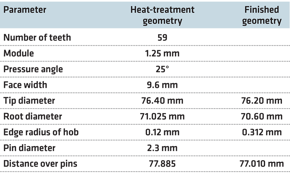
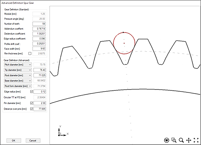
IGD takes advantage of geometric parameters commonly used in industry to construct the virtual gear geometry, including tip and root diameters, form diameters, circular tooth thickness, ball/pin diameter, and distance over balls/pins. Table 1 shows the parameters used to construct the two gear geometries for the simulation case described here — heat-treatment configuration (green shape) and the in-service configuration; Figure 1 shows IGD’s definition window with the settings for the pre-heat treatment geometry.
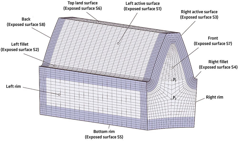
After constructing the geometry, IGD can define cyclic symmetry (if applicable) and reduce the full gear to a single tooth, mesh the gear/tooth, and define the nodes and surfaces required for post-processing. Figure 2 shows the meshed gear and post-processing surface definitions generated in IGD, which is ready for heat-treatment simulation using DANTE.
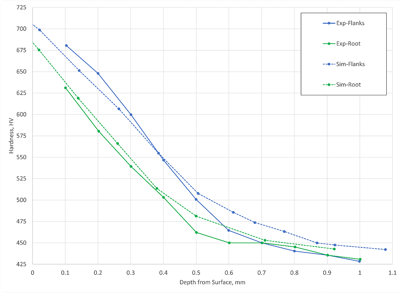
The gear described above is an actual component, with a heat-treatment process consisting of austenization, carburization, transfer from the furnace to the quench tank, quenching in oil, deep freezing, and tempering. Figure 3 compares the measured and simulated hardness profiles at the flank and root, revealing good agreement between experiments and simulation.
After the heat-treatment simulation is executed using DANTE and Abaqus, the position of the distorted nodes can be read in and reconstructed by IGD. Once the distorted geometry is reconstructed in IGD, it can be used for geometry comparison with the undistorted geometries, used for tooth contact analysis (reveal effects of heat-treat distortion on the contact pattern), or used for additional finite element analysis in Abaqus or Ansys (reveal heat-treat distortion and residual stress effect on contact and bending stresses and deflections). The additional analyses performed in IGD are carried out using the distorted geometry and residual stress predicted by DANTE. Unfortunately, detailed experimental distortion measurements were unavailable at the time of publication.
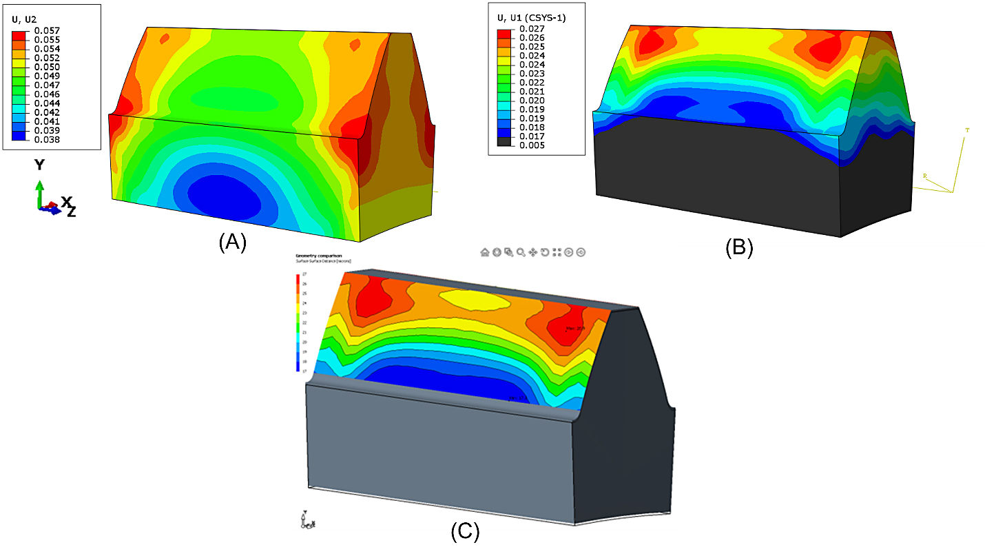
Comparing geometries is an important feature of IGD and can be directly applied to compute the deviations of the heat-treated geometry with respect to the green or finished geometries. Figure 4 compares the simulation results when (A) the global cartesian coordinates are used to evaluate the displacement along the Y-axis in Abaqus (radial direction of tooth), (B) cylindrical coordinates based on the flank geometry are used to evaluate the displacement normal to the flank, and (C) IGD is used. It should be noted that the cylindrical coordinates based on the flank and the IGD analysis are identical, with a maximum displacement of 27 µm and a minimum of 17 µm. However, these values are based on the heat-treat geometric configuration (green shape) and provide no information as to how much material removal is required, or from where, to bring the gear within the final dimensions specified on the print.
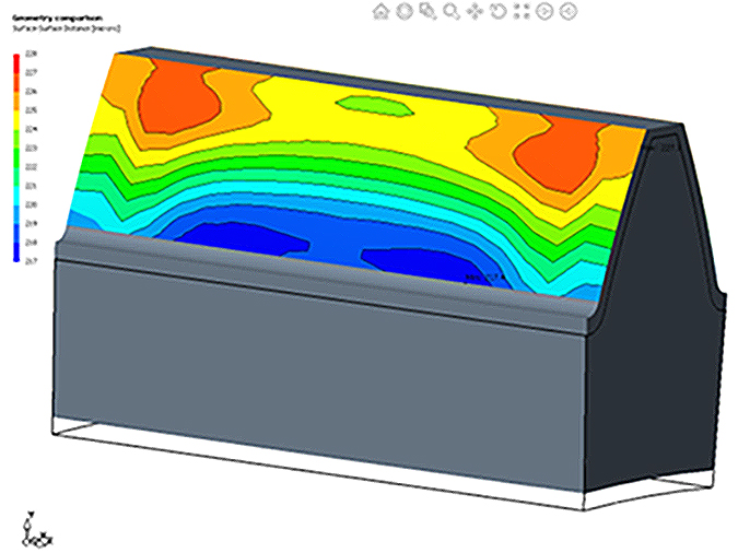
However, IGD is well suited for this type of analysis. Figure 5 shows the heat-treated distortion compared to the finished gear geometry in IGD. It can be seen that uniformly machining or grinding the gear to the final dimensions will not work, with more material needing to be removed near the tip, 222 – 229 µm, than the root, 217 – 221 µm, and not uniformly from those locations. Due to the relatively uniform carbon depth, the nonuniform material removal will result in a nonuniform hardness and residual stress distribution that may influence the gear’s in-service performance, which can then be evaluated through additional analyses.
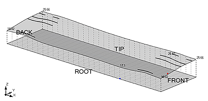
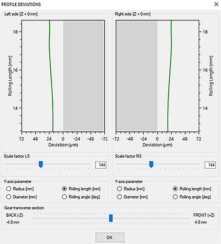
IGD also provides several features to quickly analyze tooth profiles, which is crucial to ensure that mating gears will perform as intended. Figure 6 evaluates the entire flank profile on one side of the tooth, while Figure 7 evaluates the flank profile of both sides through a transverse cut. Additional post-processing capabilities, including the distance over pins for the distorted geometry, are being developed at this time.
In summary, heat-treatment simulation has made tremendous strides in function and accuracy over the last decade but is still lacking convenient methods to relate predicted gear distortion to measured gear distortion. The utilization of IGD and DANTE brings this much needed capability to industry.
References
- Darle W. Dudley, “Handbook of Practical Gear Design,” CRC Press LLC, 1994.
- Raymond J. Drago, “Fundamentals of Gear Design,” Butterworths, 1988.
- Robert E. Smith, “Quality Gear Inspection – Part 1,” Gear Technology, pg. 32 – 38, Sept./Oct. 1994.
- Robert E. Smith, “Quality Gear Inspection – Part 2,” Gear Technology, pg. 31 – 34, Nov./Dec. 1994.
- Dennis Gimpert, “An Elementary Guide to Gear Inspection,” Gear Solutions, pg. 32 – 38, June 2005.
- Wen Shao, Mohan Yi, Jinyuan Tang, and Siyuan Sun, “Prediction and Minimization of the Heat Treatment Induced Distortion in 8620H Steel Gear: Simulation and Experimental Verification,” Chinese Journal of Mechanical Engineering, Vol. 35, Issue 126 (2022).
- Tsuyoshi Sugimoto and Dong-Ying Ju, “Influence of Thermal Boundary Conditions on the Results of Heat Treatment Simulation,” Materials Transactions, pg. 950 – 956, Vol. 59, Issue 6 (2018).
- Z. (Charlie) Li, B. Lynn Ferguson, and A. Freborg, “Modeling Application to Reduce Distortion of a Carburized and Quenched Steel Gear,” Proceedings from the 6th International Quenching and Control of Distortion Conference, pg. 200 – 211, September 9–13, 2012, Chicago, Illinois, USA.


 general practice for CQI-9 and AMS2750E")


