


In its simplest form, additive manufacturing has been used since before the common era where low temperature melting materials such as tin, silver, copper, or zinc were used to join materials in a process called brazing. This led the way for welding once man mastered the electric arc. In modern times, metal-based additive manufacturing can be classified in three main categories: powder bed fusion, sheet lamination, and direct energy deposition. Wire Arc Additive Manufacturing (WAAM) combines the well-studied process of arc welding with direct energy deposition to quickly and efficiently form parts at relatively low cost. WAAM is attractive to those entering the additive manufacturing space because of its low initial cost, high deposition rates, and wide range of materials. WAAM can be applied in large-scale production or small-scale rapid prototyping and machines can be built from existing welding systems and robotic controllers.
Computer modeling of any additive manufacturing process can be extremely difficult due to the high computational costs associated with material deposition. From a finite-element modeling standpoint, WAAM is analogous to a multi-pass welding simulation. Elemental activation, or elemental birth, is used to activate elements during the analysis to simulate the deposition of material. Common parameters for deposition are travel speed, wire feed rate, current, and protective gas flow rate. For modeling, travel speed and current are modeled, while the protective gas is assumed to be sufficient flow to protect the weld from oxidization and the feed rate is assumed to be sufficient to lay a continuous bead.
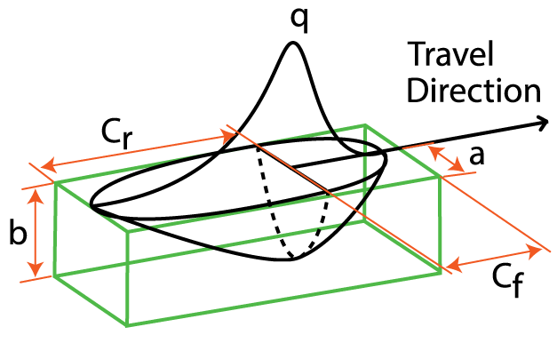
The amount of heat introduced from the weld, and the base material’s specific heat and conductivity, contributes to the solid-state phase transformations and microstructural changes in the weld and heat-affected zones. A moving heat source is required to model the deposition of melted material during WAAM. As the thermal gradient along the weld causes expansion from heating, followed by contraction from cooling, plastic deformations, distortions, and residual stresses are generated. This heat source can be described in many ways, but the Goldak double ellipsoid is the most commonly accepted model used to represent the high-localized heating present in arc, laser, and electron beam welding. Goldak, Chakravarti, and Bibby [1] proposed a new model for welding heat sources in the mid 1980s that includes a Gaussian flux distribution over a non-axisymmetric, three-dimensional volume. Their work allows for parameters that control the front (Cf), rear (Cr), width (2a), and depth (b) of the heat source applied to the elemental volume, as shown in Figure 1, which offers a flux distribution that mirrors reality. This article will use modeling to evaluate the WAAM process, using a welding tool with Goldak flux distribution that also accounts for the dynamic phase transformations in steels.
Study
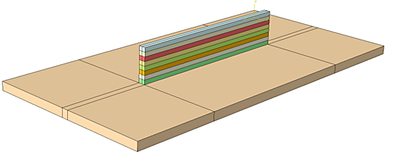
A common practice when developing a WAAM process is to build small “walls” by depositing material layer by layer on a build plate and then machining mechanical and microstructural samples to quantify the properties provided by the process. For this study, a simple finite-element model was constructed in Abaqus consisting of a 50mm by 100mm by 2.5mm build plate where eight layers of deposition welds are deposited along the center. The beads are 2mm by 1.5mm by 50mm and are deposited in the same direction after a five minute delay between passes to allow the heat to distribute into the plate. Figure 2 shows the build plate with each pass color coded, signifying deposition layers. The model was meshed with 15,123 nodes and 12,000 elements.
The complicated process of assigning the elemental activation, as well as the travel speed, current, and Goldak heating parameters, is accomplished using QustomWeld from QustomApps. Travel speed is set to 3mm/s while the power inputs are 15 Volts, 30 amps, and 70 percent efficiency. The Goldak parameters are a=1mm, b=0.75mm, Cf=1.5mm, and Cr=2.5mm. These values are held constant through each of the eight passes defined in the model.
The materials model from DANTE is coupled with QustomWeld to provide the material properties, phase transformation kinetics, and volume changes during the process. The material used for the build plate and beads in this study is AISI 1020. A sequentially coupled thermal and stress model was executed using the Abaqus solver and post processed using the Abaqus viewer.
The thermal history of a point on the center surface of the plate can be seen in Figure 3. During the first pass, the temperature of the plate sharply increases from the liquid metal deposited on the surface. Each subsequent pass raises the median temperature of this point until an equilibrium is met. The first pass is immediately quenched by the body of the plate which reaches a temperature of about 1,400°C before dropping back down to about 130°C. This spike in temperature is enough to convert the surface of the plate to austenite. The austenitized base material and bead then transform to pearlite due to the slow air cooling following the material deposition. Subsequent passes increase the temperature at the center of the plate, under the growing wall, until an average temperature of 400°C is maintained.
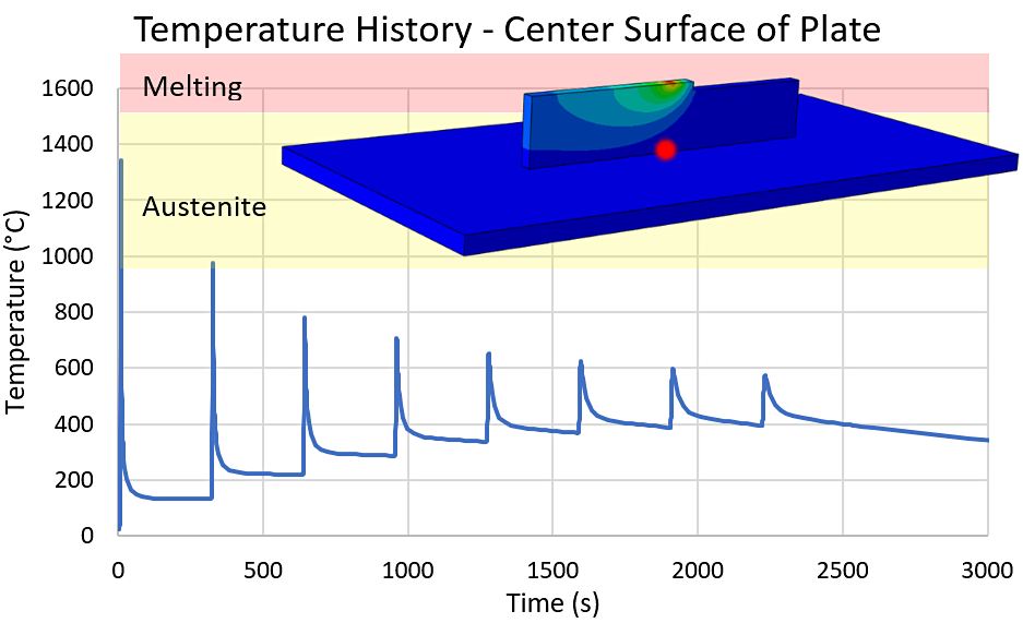
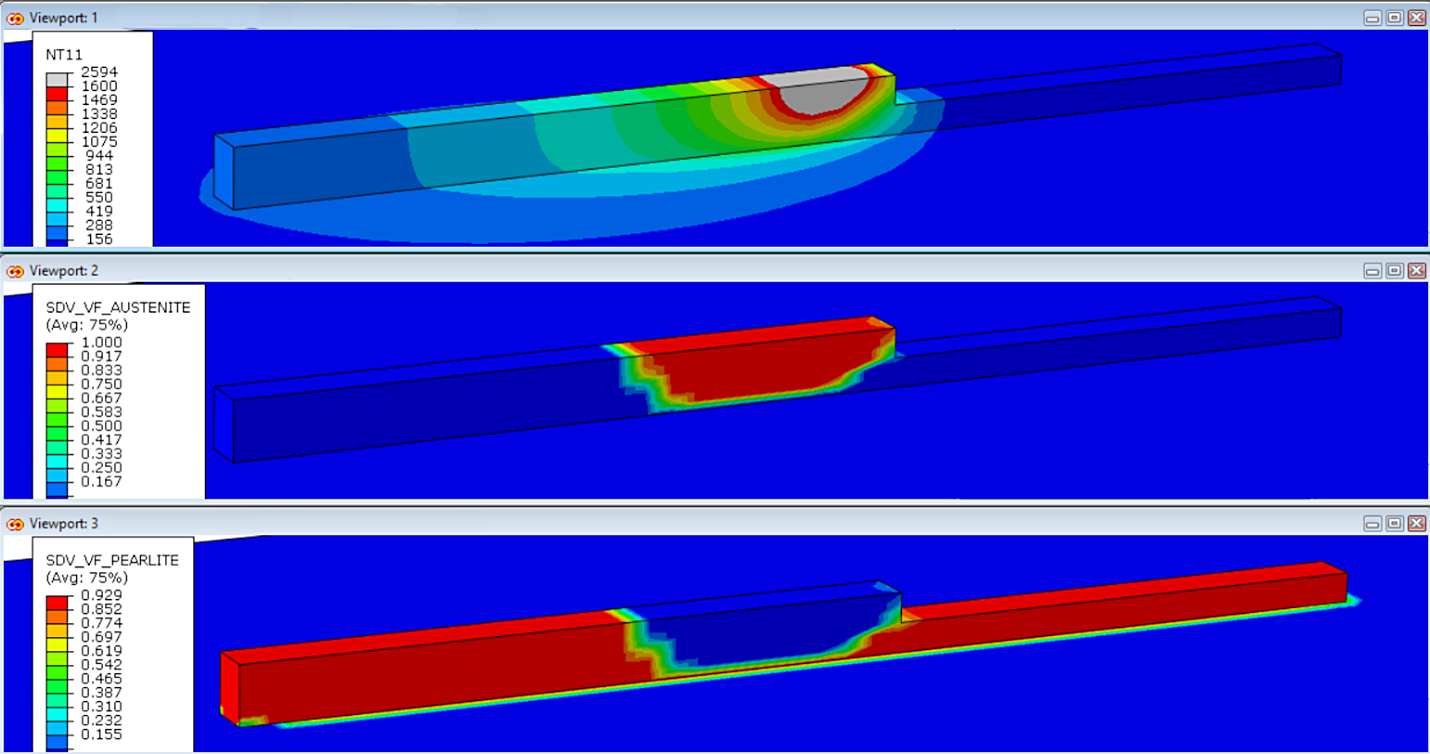
Figure 4 shows the temperature, austenite, and pearlite volume fractions mid-way through the second pass. The temperature legend is capped at the melting temperature to show the deposition of the liquid metal while the austenite contour follows closely to this high temperature zone. The pearlite contour shows clearly that the first pass is being transformed back to austenite due to the heat of the second pass before cooling again to pearlite. This transformation cycle is repeated for each subsequent pass.
The temperature history for a point on the center of the wall is shown in Figure 5. The first spike in temperature is the liquid metal deposition of pass four, activating the elements. Since the material has effectively been preheated by previous passes, the fifth pass remelts the surface of the fourth pass as it is being deposited. Even the sixth and seventh passes have enough thermal energy to reheat the fourth pass to austenite temperatures.
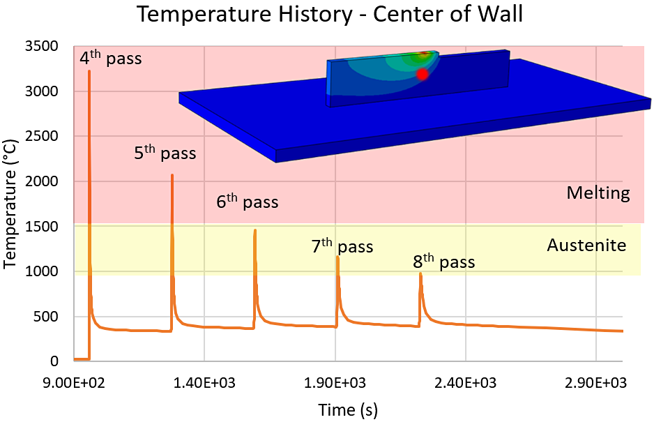
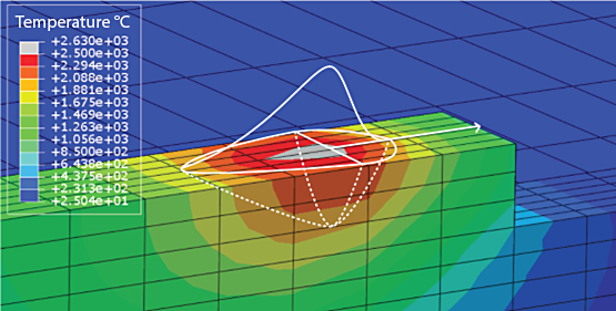
Figure 6 shows the Goldak flux distribution overlaid on the temperature contour. The temperature contour shows the double ellipsoid defined in QustomWeld with a clear heat concentration running down the centerline of the bead on every pass, consistent with the Gaussian distribution.
Conclusion
Simple models like these can tell a great story. From this study, it is clear that the power distribution should be lowered as the material comes to temperature. From the centerline temperature history in Figure 5, after pass four is deposited, it is almost completely remelted by the deposition of pass five. It is then transformed to austenite from the heat of passes six and seven. Reducing the power delivered to the part as it comes to temperature will eliminate the overheating predicted by the model.
The microstructure evolution is shown to be very dynamic due to the localized heat source produced by the Goldak parameters. The advantage of modeling is that a few simple models can help reduce the growing pains of developing a new process and shed light on refining established processes. While simple, the study described shows that the capabilities are available to model direct energy deposition with welding tools like QustomWeld, including the complex heating from the Goldak flux distribution, and the material phase evolution from DANTE.
References
- Goldak, John, et al. “A New Finite Element Model for Welding Heat Sources.” Metallurgical Transactions B, vol. 15, no. 2, 1984, pp. 299–305.,
- QustomApps – https://www.qustomapps.com/


 general practice for CQI-9 and AMS2750E")

")


