


Low pressure carburizing (LPC) processes are a popular choice in industry due to LPC’s reduced cycle time, lack of oxidation/decarburization at and near surface, better efficiency and repeatability, and power savings when compared to conventional gas carburization. [1,2] Although the benefits of LPC are evident, controlling and designing recipes for an LPC process are different than controlling and designing gas carburizing processes.
For a gas carburization process, the carbon potential is regulated and controlled by the use of various probes, limiting the carbon available at the part’s surface. Control of the carbon potential is generally sufficient to minimize carbide formation during the gas carburization of medium-alloy and some high-alloy steels. However, there is no such carbon potential control in an LPC process. Instead, a hydrocarbon gas, usually acetylene, is introduced into the chamber for a short time and then promptly evacuated. Austenite saturation is generally obtained within a few seconds during this “boost” step, and as such, the possibility of carbide formation is high. It is therefore critical to control the gas flow rate and time duration during the boost step to ensure excessive carbide formation does not occur. After the hydrocarbon gas is evacuated, the carbon that was deposited on the surface is allowed to diffuse into the surface under a near vacuum condition. These steps are repeated until the final surface carbon and effective case depth are achieved. [2]
To show the difference on case depth and surface carbon for LPC process design using a common steel alloy used in high load applications, and one in which the simple equation shown in (1) works to predict the case depth with reasonable accuracy when gas carburized, an example is presented that evaluates the differences when the recipe is designed considering and not considering carbide formation in simulation. While Equation 1 works well when applied to gas carburization, it fails to properly predict the case depth when LPC is used, and carbide formation becomes significant. [3]
![]() AISI 9310 was chosen as the steel alloy, due to its wide use in industry and its general lack of significant carbide formation during gas carburization. However, AISI 9310 can have significant carbide formation during LPC processing. DANTE’s VCarb software utility was used to design an LPC recipe given a set of final requirements. VCarb is a standalone software utility which can be used to predict the carbon, carbide, and hardness profiles for a defined LPC recipe or be used to design an LPC recipe given a set of requirements. The addition of carbide formation and dissolution predictions is critical in determining an appropriate LPC recipe for AISI 9310 using simulation. Several factors must be considered when modeling carbides, including carbide formation rates, carbide dissolution rates, and the effect of carbide size on the diffusivity of carbon in the austenite matrix. All of these material properties must be defined as a function of processing temperature and carbide size. As the carbides form during the boost step, they take carbon from the surface and limit the amount of carbon that can diffuse into the part. During the diffuse step, the carbides decompose and provide an additional carbon source.
AISI 9310 was chosen as the steel alloy, due to its wide use in industry and its general lack of significant carbide formation during gas carburization. However, AISI 9310 can have significant carbide formation during LPC processing. DANTE’s VCarb software utility was used to design an LPC recipe given a set of final requirements. VCarb is a standalone software utility which can be used to predict the carbon, carbide, and hardness profiles for a defined LPC recipe or be used to design an LPC recipe given a set of requirements. The addition of carbide formation and dissolution predictions is critical in determining an appropriate LPC recipe for AISI 9310 using simulation. Several factors must be considered when modeling carbides, including carbide formation rates, carbide dissolution rates, and the effect of carbide size on the diffusivity of carbon in the austenite matrix. All of these material properties must be defined as a function of processing temperature and carbide size. As the carbides form during the boost step, they take carbon from the surface and limit the amount of carbon that can diffuse into the part. During the diffuse step, the carbides decompose and provide an additional carbon source.
As a first step, DANTE’s VCarb was used to determine an LPC boost-diffuse schedule for AISI 9310 not considering carbide formation and dissolution. For this example, a carburizing temperature of 925° C, a surface carbon value of 0.8 percent, and an effective case depth of 1.5 mm was chosen. For AISI 9310, a carbon value of 0.35 percent corresponds to the specified hardness at the effective case depth. Given the stated requirements, DANTE’s VCarb determined an LPC recipe, which achieved the required specifications, as shown in Figure 1 (“without carbides”). VCarb determined an LPC schedule with a total boost time of 2.35 hours and a total diffuse time of 22.9 hours for the given requirements. Boost and diffuse step times can vary significantly depending on the requirements and parameters specified during recipe design.
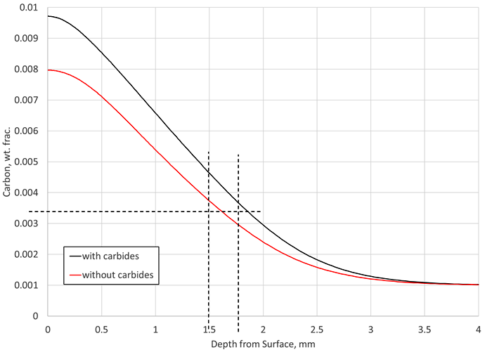
Next, this recipe that did not consider carbide formation in AISI 9310 was used to predict the carbon profile and effective case depth for the situation where carbides are considered in the simulation. Figure 1 also shows the predicted carbon profile for AISI 9310 when carbide formation is considered in the simulation (“with carbides”). Again, these two predicted carbon profiles are for the same LPC schedule. It can be seen in Figure 1 that once carbides are considered and the same schedule used, the surface carbon is raised to 0.97 percent and the effective case depth is now approximately 0.25 mm deeper.
The prediction revealed there are effectively no carbides at the end of the process, even though carbide formation was considered. The final profile does not indicate whether or not carbides were forming and dissolving during the process. The end state of the material does not give any indication as to the transient behavior of the carbide morphology occurring during the process. If carbides form and dissolve during the boost-diffuse steps, they will provide an additional carbon source not accounted for if carbide formation is ignored in the simulation. The lack of carbides predicted at the end of the LPC process could just mean that the final diffuse time and the size of the carbides formed were such that all the carbon in carbide form was able to dissolve back into the austenite matrix.
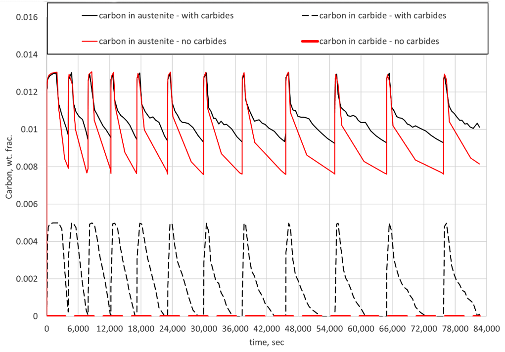
Figure 2 compares the effect of carbide formation and dissolution in simulations versus the assumption of no carbide formation for the same LPC schedule. Shown are the predicted carbon in the austenite matrix and carbon in carbide form as a function of time for the given schedule. It can be seen that carbides do indeed form during each boost step but are effectively dissolved after the subsequent diffuse step. However, the dissolution of the carbides results in higher surface carbon values at the end of each diffuse step when considering carbide formation in the simulation. This is completely acceptable for component processing and service, but the carbide morphology must be considered when using predictive tools to determine LPC recipes for steel alloys. If not, the possibility of having too much carbon on the surface and/or having too deep of an effective case depth is a real possibility.
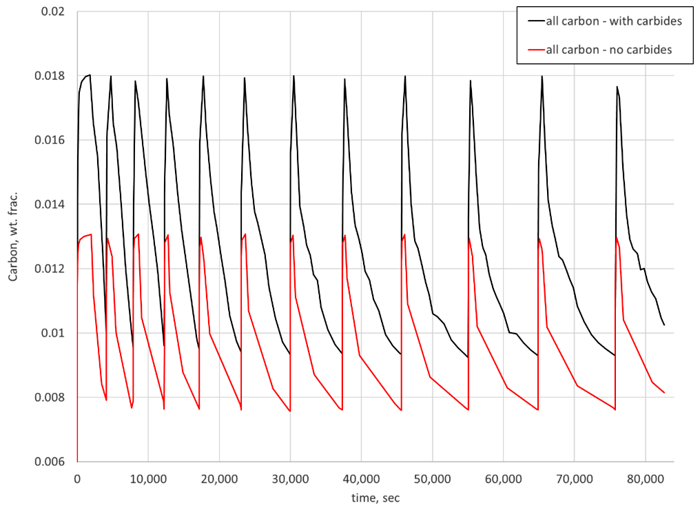
Another interesting way to view the results is to look at the total carbon available during each step. In DANTE, a variable is tracked that is the sum of the carbon in austenite and carbon in carbide, referred to as “All Carbon.” Figure 3 shows the “all carbon” variable predicted for the two simulations. As can be seen, when carbides are not considered in the simulation, the surface carbon can reach saturation at the carburizing temperature and go no higher. When carbide formation is considered, the surface carbon exceeds saturation due to the formation of carbides. For the case considered, this amounts to an additional 0.5 percent carbon available at the surface of the component during the subsequent diffuse step. This additional carbon, present in carbide form, should dissolve during the diffuse step, given the size is small enough to properly dissolve.
In conclusion, steel alloys that have been historically gas carburized with no carbide-related problems can begin to have carbide formation if LPC is used instead. This is due to the increase in carbon available at the surface during an LPC process when compared to a gas carburization process. For accurate simulation of the process, carbide morphology must be considered. DANTE’s simulation tools consider carbide formation and dissolution to offer a more accurate prediction when designing or evaluating low pressure carburization recipes.
References
- Pawel Rokicki and Kamil Dychton; Acetylene Flow Rate as a Crucial Parameter of Vacuum Carburizing Process of Modern Tool Steels, Archives of Metallurgy and Materials, Vol. 61, No. 4, pg. 2009 – 2012, 2016.
- Ogun Baris Tapar, Matthias Steinbacher, Jens Gibmeier, and Jeremy Epp; Investigation of the Effects of Low-Pressure Carburizing Process Parameters on Microstructural Evolution by Means of In Situ Synchrotron X-Ray Diffraction, Advanced Engineering Materials, 2021.
- B. Lynn Ferguson, Zhichao Li, Justin Sims, and Tianyu Yu; Vacuum Carburizing Steel Alloys Containing Strong Carbide Formers, Proceedings of the 29th ASM Heat Treating Society Conference, Oct. 24 – 26, 2017, Columbus, OH, U.S.A.


 general practice for CQI-9 and AMS2750E")


