


The finish machining of a gear is undoubtedly one of the most important manufacturing steps. It sets the geometry, surface condition, and residual stress profile that will see service conditions. Many heat treatments exist that induce favorable compressive residual stresses in the near surface of the gear, improving fatigue life. However, a chain is only as strong as its weakest link and the situation is no different for a gear’s working surfaces; its fatigue life is only as good as the smallest near-surface compressive stress. Given that most quench-hardening processes result in a nonuniform size change, the material which must be removed to ensure the gear is within the dimensional requirements must also be removed nonuniformly. Although the dimensions are brought within the tolerances specified by the gear designer, the final residual stress and hardness profiles are at the mercy of the amount of material which must be removed.
If properly executed, a case-hardening process such as carburization or induction hardening should induce compressive residual stresses from the surface to approximately the case-core interface. The compressive stress then transitions to a tensile stress just below the case-core interface. The residual stress state is in static equilibrium and any modification to the stress profile, by removing a layer of material for example, will create a state of nonequilibrium. To correct the nonequilibrium state, the residual stress will change. Much work has been done to evaluate the effects of grinding, one of the most common finishing operations, on the rebalancing of the residual stress profile in gears. Depending on the amount of material removed and the amount of material removed during each pass, the stress change can be minimal or significant. [1 – 4] In conjunction with the rebalancing, grinding processes can induce a temperature increase at the near surface of the workpiece due to frictional effects. If the temperature is kept sufficiently low, there will be no detrimental effects to the material’s properties. As the surface temperature begins to approach 200°C however, several microstructural changes may occur. The first, depending on the tempering temperature employed after quench hardening, is the possibility to reduce the hardness and residual stress by over-tempering the component. If the temperature continues to rise, significant stress relaxation may occur. If the temperature rise is not reasonably controlled, the temperature may get high enough to induce a phase change to austenite. An unintended phase change at this stage of the manufacturing process could result in catastrophic failure if the component is placed directly into service. [5 – 6]
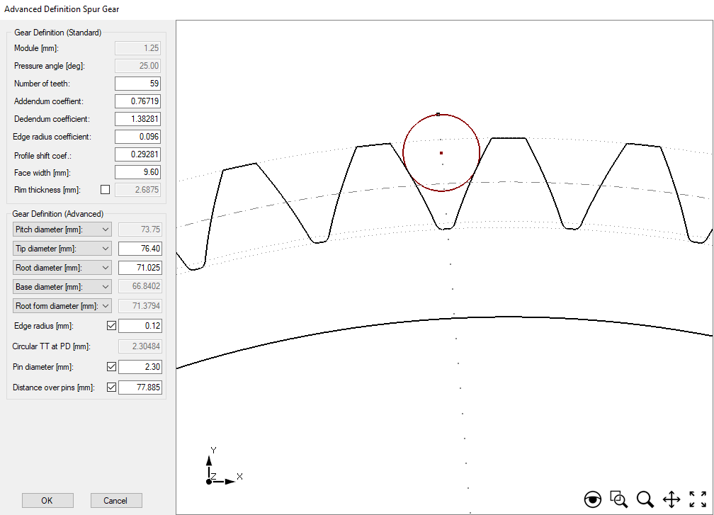
The deviations to the tooth’s flank slope profile are of the utmost importance to the gear’s in-service performance; particularly with respect to contact stress, bending stress, wear behavior, and operational noise. Due to variations in a component’s cross-sectional thickness and variations inherent to local-fluid behavior, most quenching processes will alter the slope profile of the tooth flank. This deviation must be corrected before the gear is able to enter service. [7 – 9] Heat-treatment simulation software, when combined with powerful post-processing algorithms designed to evaluate simulated gear distortion, can be an indispensable tool to design and process engineers. As discussed in the December 2022 Metal Urgency column (https://thermalprocessing.com/media/FlipBook/2022/1222/1222-TP.html#p=18), the heat-treatment simulation software DANTE can predict the distortion and stress from the quench-hardening process of steel gears. Rochester Institute of Technology’s software program, Integrated Gear Design (IGD), is a powerful pre- and post-processing software tool used for gear design and in-service performance evaluations. When the two softwares are used together, simulated gear distortion can be quickly and easily evaluated and compared to measurements of actual components. [10] This article will take advantage of the powerful capabilities afforded by the combination of the two software programs to evaluate the effects of different quenching conditions on the flank slope profile deviation of a spur gear made of carburized AISI 9310. The gear parameters used to generate the 3D CAD gear geometry in IGD are shown in Figure 1.
The heat-treatment process, simulated using DANTE and Abaqus, consisted of the following steps: austenitization, carburization, transfer from the carburizing furnace to the quench tank, oil quenching, and tempering. The focus of this study was to evaluate the effect of various quenching speeds on the flank slope profile deviation. A nominal oil quench was defined as the heat transfer coefficient (HTC) as a function of part surface temperature data set available as a generic HTC definition in DANTE. This curve was scaled by 25, 50, 75, 125, 150, 175, and 200 percent to account for different oil types or variations which may be present during a quenching process.
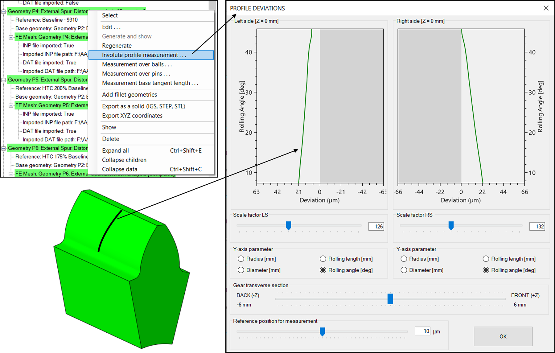
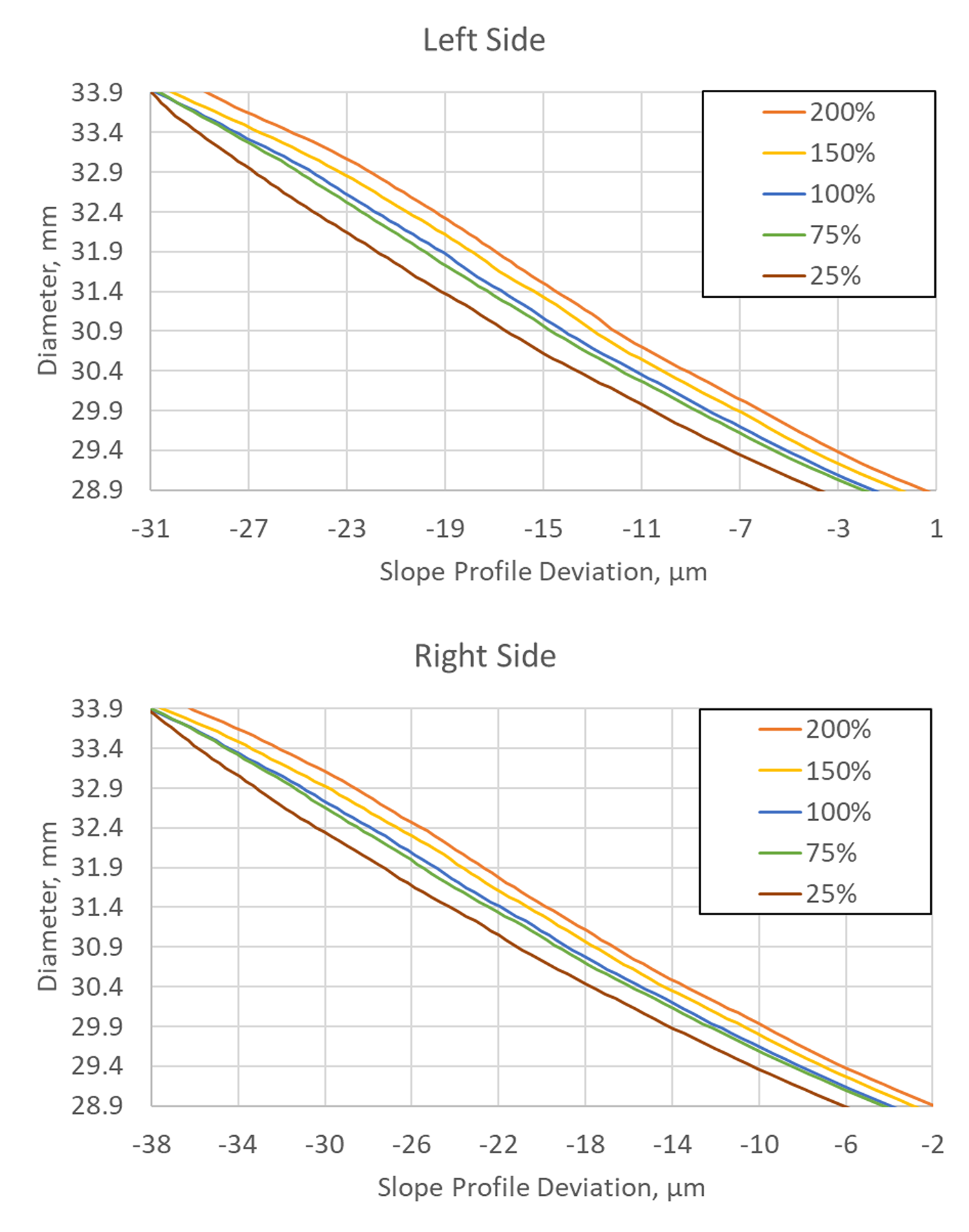
IGD was used to quickly evaluate the flank slope profile deviation of both flank surfaces, as shown in Figure 2. The data can be exported as an Excel file and further manipulated and compared. Figure 3 shows the slope profile deviation over the flank surface for five of the eight cases simulated; others removed for clarity. For the simulated geometry and processing conditions, the profile variation remained nearly consistent over the length of the flank between the cases, indicated by the near-parallel lines in Figure 3. However, at any given location on the flank there is an approximately 5 µm difference between the fastest and slowest cases evaluated. Depending on the case depth and the residual stress gradient, this may create inconsistent performance between supposedly similar gears. From Figure 3, much more material would need to be removed near the tooth tip, compared to the amount removed near the root to correct the slope profile.
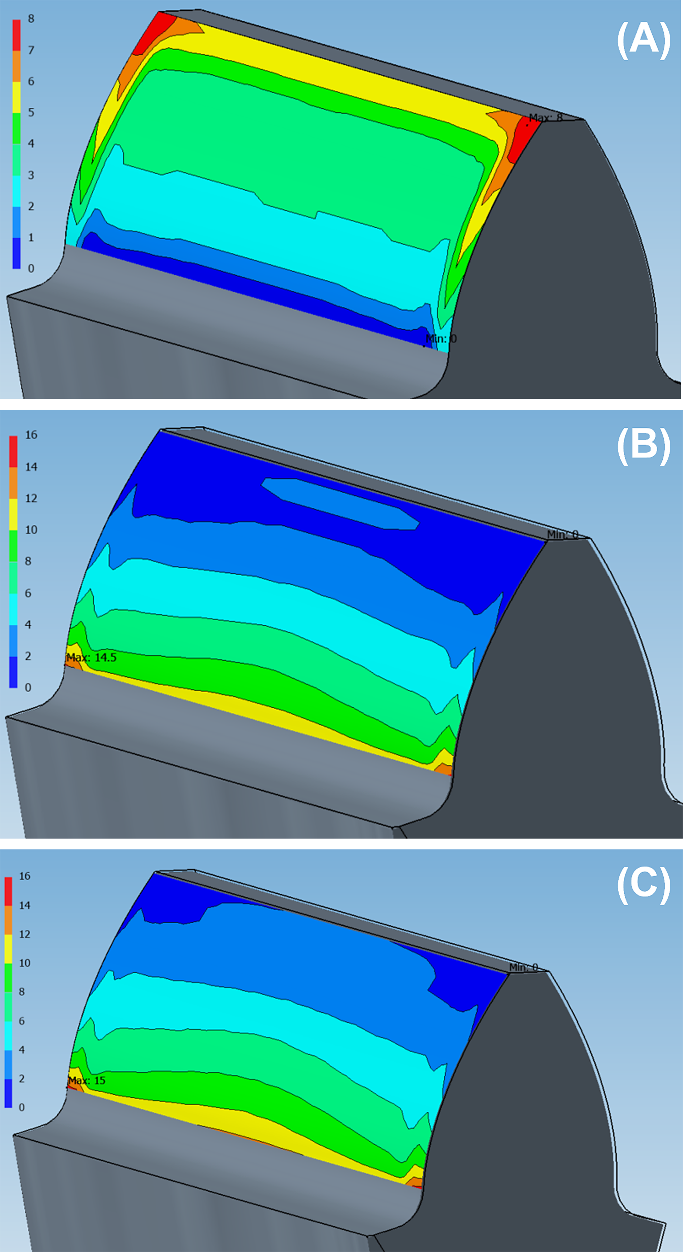
The total slope profile deviation, a commonly reported value during quality assessments, can also be determined. Table 1 shows the total flank slope profile deviation for the eight cases evaluated. The slower quench rates significantly affect the total slope profile deviation, while the faster quench rates do not. However, from Figure 3 it is clear that the faster quench rates do have an effect on the size of the flank, which must be known to produce a dimensionally accurate final component. Figure 4 shows the contour maps of the left flank slope profile deviation generated in IGD. Viewing the results over the entire flank helps illuminate differences between processing conditions and exactly how a flank profile is distorting.

Evaluating the slope profile deviation induced by various quenching conditions is just the first step in a full evaluation of the effects on hardness and residual stress. The next step would be to evaluate the effect of material removal on the residual stress and hardness, noting any conditions that result in an unfavorable condition. Finally, the new hardness, residual stress, and dimensions can be brought back into IGD to conduct tooth contact analysis and/or loading simulations to evaluate and compare various heat treatments on in-service performance.
In conclusion, IGD and DANTE can provide a powerful tool to evaluate the effects of heat treatment on gear properties and performance. DANTE lifts what was once considered a black box in heat treatment, revealing the causes and effects incurred during heat treatment of steel gears. Additionally, what was once considered a near impossible task by heat-treatment simulation software, IGD easily evaluates simulated gear distortion using the same measurements that are used in industry to assess gear quality.
References
- Yamin Shao, et al.; “Experimental Investigation of Residual Stress in Minimum Quantity Lubrication Grinding of AISI 1018 Steel,” Journal of Manufacturing Science and Engineering, Vol. 138, January 2016.
- Jeffrey Bunn, Thomas Watkins, and Camden Hubbard; “Grinding Induced Changes in Residual Stresses of Carburized Gears,” Gear Technology, March/April 2009.
- Karl Jakob Winkler, Thomas Tobie, and Karsten Stahl; “Influence of grinding zones on the tooth root bending strength of case carburized gears,” Forsch Ingenieurwes (2022) 86:661–671; 2021.
- W. Stachurski, et al.; “Effect of grinding conditions of gears made of 20MnCr5 steel after single-piece flow heat treatment on the condition of the surface layer of the tooth working surface,” Archives of Materials Science and Engineering, Vol. 120 – 2, April 2023.
- Omar Fergani, et al.; “Temperature Effects on Grinding Residual Stress,” 6th CIRP International Conference on High Performance Cutting, 2014.
- J. Sawiki, et al.; “The influence of workpiece speed on microhardness and residual stresses in vacuum-carburised 20MnCr5 steel using the single-piece flow method,” Archives of Materials Science and Engineering, Vol. 115 – 2, June 2022.
- Jing Wei, Licun Wang, and Wei Sun; “Effects of flank deviation on load distributions for helical gear,” Journal of Mechanical Science and Technology, Vol. 25 – 7, 2011.
- Tao Luo, et al.; “Effects of helix deviation on load distributions and bending stresses of continuous engaged helical gear drives,” Advances in Mechanical Engineering, Vol. 7 – 6, 2015.
- Raynald Guilbault, L. Cloutier, and Claude Gosselin; “Helical Gears, Effects of Tooth Deviations and Tooth Modifications on Load Sharing and Fillet Stresses,” Journal of Mechanical Design, Vol. 128, March 2006.
- Justin Sims and Alfonso Fuentes Aznar; “Gear inspection methods from heat-treat simulation,” Thermal Processing, Vol. 11 – 12, December 2022.


 general practice for CQI-9 and AMS2750E")


