


Surface hardening heat treatments have been shown to significantly improve strength, mitigate wear, and enhance the fatigue performance of wrought, cast, and sintered ferrous components [1]. As a result, surface hardened components are often placed in challenging applications that demand additional scrutiny to confirm specific design requirements such as surface hardness, case depth, and case microstructure. Case depth is of particular interest to the product designer because it characterizes the gradient in material properties near the surface, where stresses tend to be the highest.
Case depth can be defined a variety of ways, but is routinely quantified by measuring both the total and effective case depths of the component via physical testing, chemical testing, or microstructural examination. Total case depth has a well-accepted definition, but effective case depth can be defined in several ways — and, in some instances, defining it is unnecessary. Although an assortment of surface hardening technologies is available in industry, this discussion will be limited to defining case depths resulting from the carburizing and induction hardening of wrought steel.
Measuring Case Depth
Accurately measuring the surface hardened case depth of a component is not a task that should be trivialized. Consequently, metallographic specimens are typically specified to validate a surface hardening process, with hardness testing being the most widely preferred method of characterizing the surface hardened layer. Figure 1 shows three preferred techniques for determining case depth profiles via hardness testing. All three techniques require careful sample preparation and sound hardness testing methodology to ensure data validity. Although the cross-section procedure is the primary method used due to its simplicity, the taper and step methods can be very useful in specific scenarios such as characterizing shallow case depths or very coarse microstructures that require higher loads (larger indentations) to reduce variability in the data.


Defining Case Depth
Understanding the design intent of a component allows aspects like case depth validation to be appropriately defined. Following are some commonly specified values used to characterize surface hardened case depth profiles:
• Surface hardness: Typically specified as a range (minimum and maximum).
• Depth to minimum specified surface hardness: The beginning of the case-core transition region.
• Total case depth: Generally defined as the distance from the surface (measured perpendicularly) to a point where the differences in the chemical or physical properties of the case and core may no longer be distinguished [1–3].
• Effective case depth: Approximately 66 percent to 75 percent of the total case depth [1], but often specified as the depth to a specific hardness.
Of the four terms used to define case depth, effective case depth is the most ambiguous. In fact, one could argue that induction hardening does not require effective case depth to be defined because of the relative abruptness of the case-core transition. Simply determining the depth to the minimum specified surface hardness and total case depth should adequately define the hardness profile of the majority of induction hardened components.

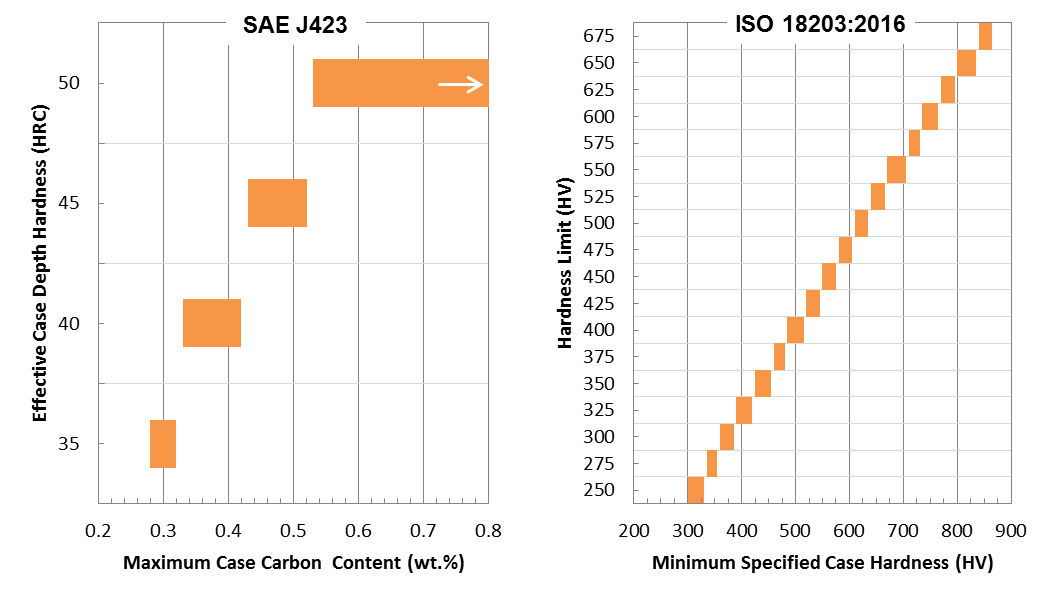
Figure 4 shows two industry standards that are often referenced to define effective case depth (also known as “hardness limit” in ISO 18203) in the surface hardening of steels. The SAE standard defines the effective case depth as a function of the carbon content of the case, while ISO specifies effective case depth strictly by the minimum specified hardness of the case. Literature justifying which method is more appropriate from a strength or fatigue improvement perspective is very limited, suggesting either definition is sufficient. However, a paper by Fett [5] concluded that the torsional strength of induction hardened medium-carbon steel shafts more closely correlates with effective case depth, while the fatigue performance more closely correlates to total case depth.
References
- J.R. Davis, Surface Hardening of Steels: Understanding the Basics, Materials Park, OH: ASM International, 2002.
- [SAE Standard J423, “Methods of Measuring Case Depth,” in SAE Ferrous Materials Standards Manual, Warrendale, PA: Society of Automotive Engineers, 2004.
- ISO Standard 18203:2016, “Steel — Determination of the Thickness of Surface-hardened Layers,” International Organization for Standardization, Geneva, Switzerland, 2016.
- L.M. Rothleutner, “Assessment of the Microstructure and Torsional Fatigue Performance of an Induction Hardened Vanadium Microalloyed Medium-carbon Steel,” Dissertation, Colorado School of Mines, 2016.
- G.A. Fett, “Importance of Induction Hardened Case Depth in Torsional Applications,” Heat Treating Progress, vol. 9, no. 6, pp. 15–19, October 2009.


 general practice for CQI-9 and AMS2750E")


