


Low pressure carburizing (LPC) is quickly gaining popularity across many industries due to LPC’s reduced cycle time, lack of oxidation/decarburization at and near surface, better efficiency and repeatability, and power savings when compared to conventional gas carburization. [1,2] However, designing the boost-diffuse schedule is anything but straightforward, especially for steel alloys containing strong carbide-forming elements (Cr, Mo, V, and W). [3] In light of this difficulty, many furnace manufacturers now include software with their LPC furnaces which are capable of designing the LPC schedule based on a few simple inputs. This works great for certain alloys, but once strong carbide-forming elements are introduced to the alloy system, a simple diffusion model, based on Fick’s Second Law, will no longer suffice.
During a boost step, carbon quickly reaches the saturation limit in austenite on the surface of the part. If alloy elements with an affinity for carbon are present, carbides will form and grow. Once the diffuse step begins and the carbon-carrying gas is evacuated from the furnace, the carbides are able to dissolve, providing additional nascent carbon for diffusion. If the carbides are not allowed to dissolve significantly during the diffuse step, they can block further carbon diffusion and result in unacceptable microstructural features in the final part. Therefore, the modeling of carbide formation and dissociation must be included for accurate LPC simulation predictions.
In addition to including a carbide model, the LPC process simulation should also include any relevant steps where carbide dissociation and/or carbon diffusion can occur. For any process specification requiring a slow cool and reheating step after carburizing, as opposed to quenching directly from the carburizing temperature, the reheating step should be considered for an accurate carbon profile prediction. Including any additional process heating steps in the simulation will help ensure the predicted carbon profile matches the carbon profile witnessed in production.
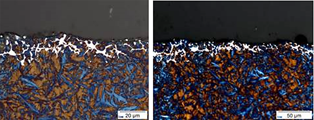
The importance of including carbides and a reheat step for AISI 9310 undergoing an LPC process, with a subsequent reheat, will be demonstrated in this article. By controlling the carbon potential in the furnace, atmospheric carburizing of 9310 results in few carbide issues. However, the formation of detrimental carbides when using LPC to carburize 9310 is a real possibility. Figure 1 shows unacceptable carbides at the near surface during LPC trials for AISI 9310. The process described in “The Effect of the Quenching Method on the Deformations Size of Gear Wheels after Vacuum Carburizing” is simulated using DANTE’s VCarb software tool and the results compared to the measurements reported in the publication. The reported process uses three boost – diffuse pairs (6 – 13, 4 – 34.5, 3.5 – 16 minutes) and the part is cooled to room temperature after carburizing. The part is then subjected to a hardening cycle, which includes austenitization, soaking, and quenching in oil.
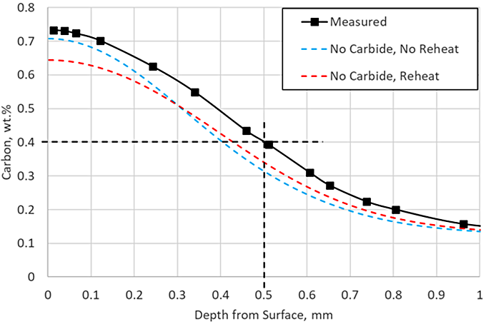
The first two simulations executed exclude carbide formation. This is a common assumption made to simplify the model and reduce the amount of material data needed. Models describing carbide kinetics can be challenging and time-consuming to develop and validate. Once developed, each alloy to be simulated would need to be characterized during LPC processing. Figure 2 shows the carbon profile prediction when carbides are not considered, with and without a reheating step. Without including the reheat, the surface carbon concentration is predicted to nearly match the measurement, but the effective case depth (ECD) is underpredicted by 0.1 mm. Once the reheat is included, the ECD prediction is closer to the measurement, but the surface carbon is underpredicted by 0.1 percent.
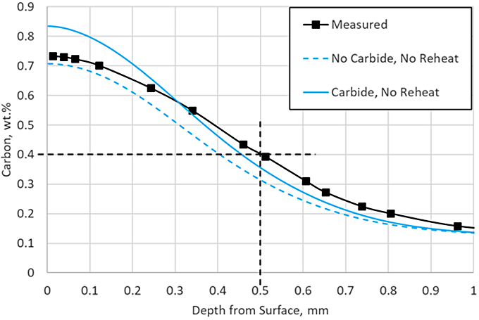
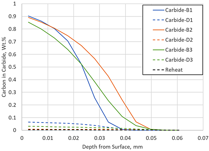
DANTE, including VCarb, includes a standard carbide model which includes model parameters for AISI 9310 carbide kinetics during LPC processing. Figure 3 compares the predicted profile with and without carbide formation, neglecting the reheat step, to the measured data. Including carbide formation overpredicts the surface carbon by 0.1 percent, but the ECD prediction is nearing the measured data. The addition of the carbide prediction serves to provide more than additional carbon to the surface; it also provides an additional carbon source for diffusion. Figure 4 shows the carbon in carbide form for each of the three boost – diffuse pairs. It is clear that a substantial amount of carbon is taken up into carbides during the boost step, 0.9 percent at the near surface, and then dissociates into nascent carbon and diffuses into the part during the diffuse step.
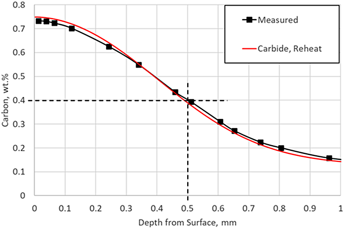
There is very little carbon in carbide form at the end of this particular LPC schedule, but the reheat step ensures there are no carbides present as the part enters quench; in practice, a long final diffuse is generally used to ensure no carbides persist after carburizing. Including the reheat step with the carbide prediction in the simulation yields an identical match to the experimental data, as shown in Figure 5.
Conclusion
The importance of including carbide formation and dissociation when simulating an LPC process for steel alloys containing strong carbide-forming elements was demonstrated and it was shown that carbide models are critical to an accurate carbon profile prediction. It was also shown that it is possible to form carbides during the LPC process, but not have any after the carburizing process. It is therefore imperative to characterize medium- and high-alloy steels for carbide formation if undergoing an LPC process.
While LPC recipe development can be accomplished through trial and error, it has been reported that some high-alloy steels used in the aerospace industry can take years to develop a single LPC recipe yielding acceptable results. This painstaking process does not even consider any effect of geometry on diffusion and carbide kinetics, which can be substantially more than atmospheric carburizing if the LPC process is not well controlled and/or the recipe is not well designed. Therefore, simulation is a more efficient method than trial and error for LPC recipe design. While it is true that characterizing the carbide kinetics for a steel alloy is time-consuming, though once complete, the model can be used to optimize a unique LPC recipe for each new geometry using that steel alloy. Simulation can also be used to optimize any surface carbon or case depth discrepancies between convex (higher surface carbon and shallower case depth) and concave (lower surface carbon and deeper case depth) geometric features.
References
- Pawel Rokicki and Kamil Dychton; Acetylene Flow Rate as a Crucial Parameter of Vacuum Carburizing Process of Modern Tool Steels, Archives of Metallurgy and Materials, Vol. 61, No. 4, pg. 2009 – 2012, 2016.
- Ogun Baris Tapar, Matthias Steinbacher, Jens Gibmeier, and Jeremy Epp; Investigation of the Effects of Low-Pressure Carburizing Process Parameters on Microstructural Evolution by Means of In Situ Synchrotron X-Ray Diffraction, Advanced Engineering Materials, 2021.
- B. Lynn Ferguson, Zhichao Li, Justin Sims, and Tianyu Yu; Vacuum Carburizing Steel Alloys Containing Strong Carbide Formers, Proceedings of the 29th ASM Heat Treating Society Conference, Oct. 24 – 26, 2017, Columbus, OH, U.S.A.


 general practice for CQI-9 and AMS2750E")


