


Steel powertrain gears are commonly carburized and quench hardened to improve strength and wear characteristics. However, solid-state phase changes occurring within the steel during the hardening process can introduce large distortion. To control the distortion of complex gear designs, press quenching is often used in industry. [1] Press quenching is a process that uses specially designed tooling and a press machine to help control the distortion of complex geometries being quench hardened. The press unit is fitted with oil channels to direct cooling fluid at the part. It should also be noted that the goal of press quenching is not to “hold” the part in place but to encourage deformation of the component in a controlled and predictable manner.
A previous Metal Urgency column, “Modeling Can Improve Press Quenching Process,” [2] discussed using the heat-treatment simulation software DANTE to evaluate a press-quenching process of a straight bevel gear experiencing radial distortion issues of its bore. [3,4] The previous article explored modifying the press quench tooling to improve the radial distortion response, with the main focus being on the bore of the gear and the improvement gained from replacing the expander used to control the bore dimension with a solid plug. However, the astute reader would have noticed the gap between the gear and the “lower outer die,” as shown at A in Figure 1 (upper left). The defined gap is not an arbitrary choice, and the gap distance will have a significant effect on the bevel distortion.
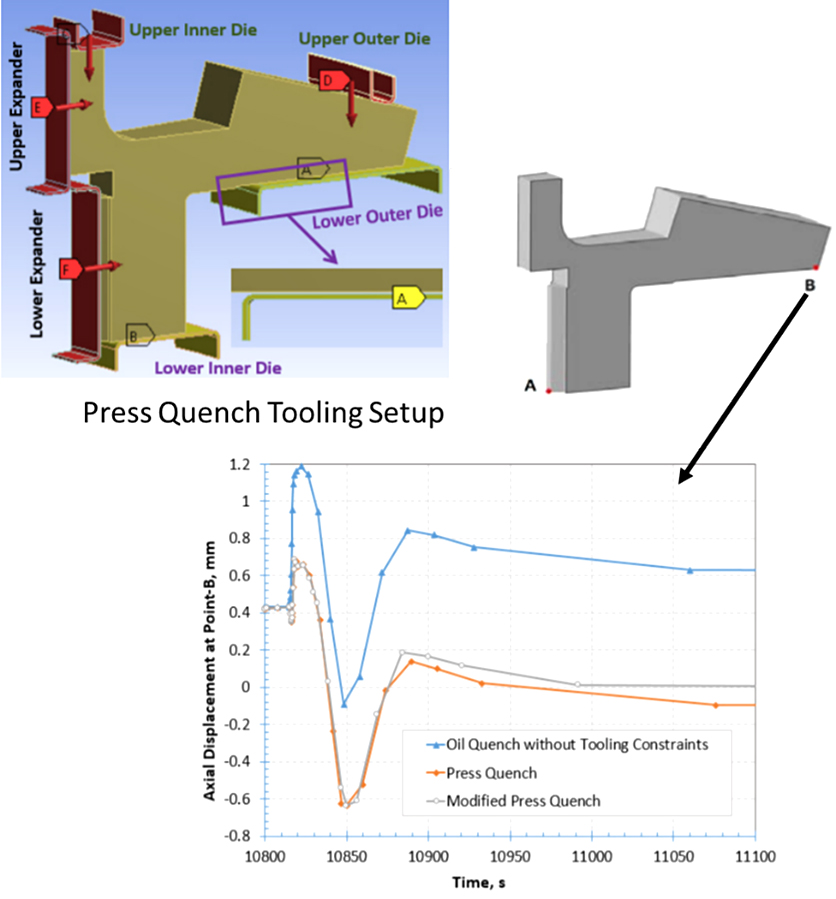
The plot in Figure 1 (lower), axial displacement of point B versus time, shows the effect the lower die can have on the bevel distortion during the process. The load on the “upper outer die” pushes the bevel down while the component is in the austenite phase and holds it against the “lower outer die.” As the austenite is transformed to martensite, the expansion to martensite causes the bevel to separate from the “lower outer die,” and nearly return to its original position (zero on the plot).
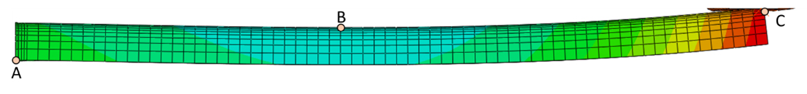
While this may seem easy enough, the design of the bevel support, labeled “lower outer die” in Figure 1, is not a trivial activity. There are three major parameters associated with designing the bevel support: the load placed on the “upper outer die,” the radial location of the support under the bevel, and the gap between the bevel and the “lower outer die.” All of these parameters significantly affect the final deflection of the bevel gear tip at the outer diameter and the overall bow of the tooth. These two distortion modes are described by Figure 2. The deflection is determined by subtracting the vertical displacement at point C (the free end of the beam) in Figure 2 from the vertical displacement at point A; point A is fixed, so the displacement is always zero at point A. The overall bow is determined by subtracting point C from point B. It should be noted that point C is generally at the free end of the beam, but the location of point B will vary depending on the values of the major parameters previously mentioned, as will be shown.
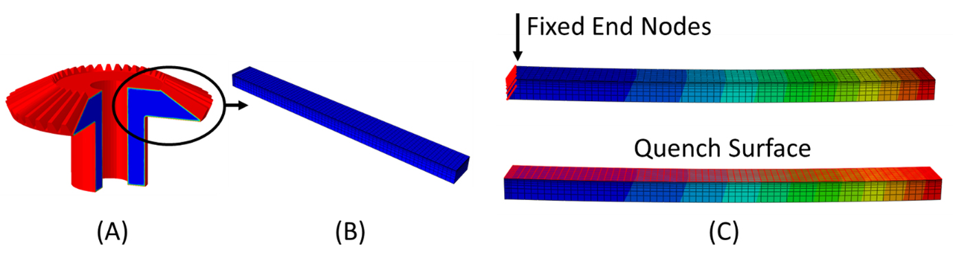
To explore the effects of these parameters on the two critical distortion modes, a simplified model was constructed to mimic the bevel teeth of a bevel gear. The first simplification was to assume the bevel teeth behaved as a cantilever beam. Figure 3A shows a 270° section of the original CAD geometry and Figure 3B shows the cantilever beam used for this study. It was also assumed that one end of the beam was completely fixed, as it is attached to the gear hub, and only the top surface was quenched, to mimic the increased cooling rate provided by the additional surface area of the gear teeth. This is shown in Figure 3C.
In the design of actual equipment, the gear geometry being processed should be modeled. However, the simplifications made here can provide insight into how these three parameters interact to manipulate the final distortion of the component after a press-quenching process. Simplifications such as this can also be made in the initial design iterations to quickly gain an understanding for how certain load and die configurations affect distortion. The accuracy of this simplification can be improved upon if the beam’s stiffness is equivalent to the gear tooth’s stiffness.
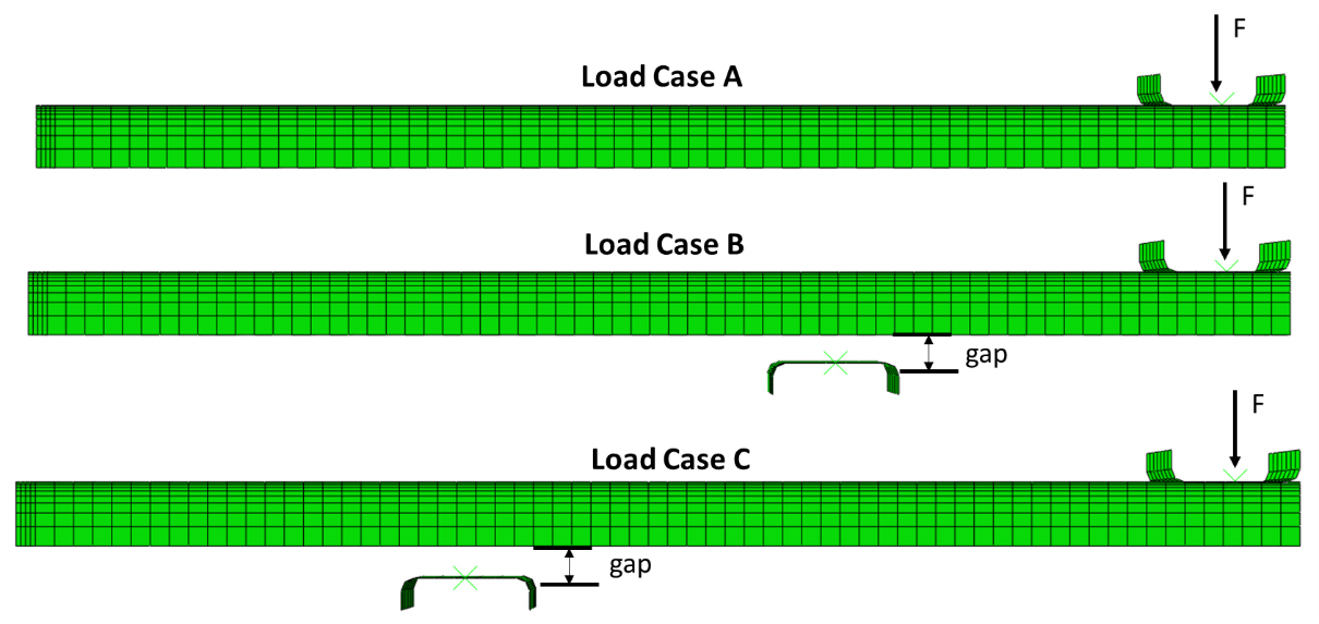
Figure 4 shows the three loading cases examined: Load Case A applies a load to the free end of the beam, by means of an upper die, with no lower die. The force was varied to evaluate distortion of the beam from this configuration. A zero-load condition was also executed for Load Case A to evaluate the distortion if the beam was quenched without tooling constraints. It is always good practice to evaluate the geometry without constraints to ascertain how the geometry wants to naturally deform, prior to any attempt at designing the tooling configuration and loading scheme. Load Case B applies the load to the free end of the beam also but uses a lower die approximately 1/3 distance from the free end. The load and lower die gap were varied to evaluate the effects on distortion. Load Case C also uses an end load and lower die, but the lower die is approximately 2/3 distance from the free end. The load and lower die gap were varied to evaluate the effects on distortion from this loading configuration.
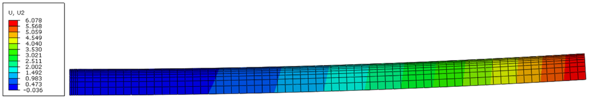
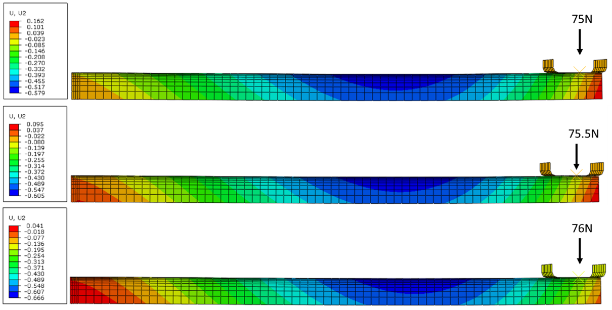
To begin the study, a model was executed that placed no constraints on the geometry. This condition should always be evaluated first to determine natural distortion modes induced by the geometry and the cooling conditions. Figure 5 shows the results of the free quench, no constraints model. The results show a tip deflection of 6 mm, with a bow of approximately the same amount. Incremental loads were subsequently placed on the outer die of Load Case A until the beam straightness became optimized. A load of 75.5 N was found to offer the best results, with respect to minimum tip deflection and overall straightness. Figure 6 shows how sensitive the distortion can be for geometries such as this; a 1 N load can alter the axial distortion by 100 µm. While this may not seem like a large value, many machines inherently have this level of variation and as tolerances become ever more stringent, 100 µm becomes a big deal. Dimensional tolerances allowed for the gear geometry will also alter the distortion from press quenching, as slight dimensional changes can alter a material’s resistance to bending.
The location of the lower die for Load Case B was chosen by evaluating the low spot from Load Case A (the dark blue area in Figure 6) and placing the die directly below it. The load determined in Load Case A was used and the gap distance adjusted until the beam’s straightness was optimum for the given load. A gap distance of 5 mm, with a 75.5 N load, was determined to be the best for Load Case B. The lower die position for Load Case C was arbitrarily chosen to be approximately 2/3 distance from the free end and the same 75.5 N load was used with varying gap distances. A gap distance of 2 mm, with a load of 75.5 N, was determined to be the best for Load Case C. Figure 7 shows the results for each optimum condition using a 75.5 N load.

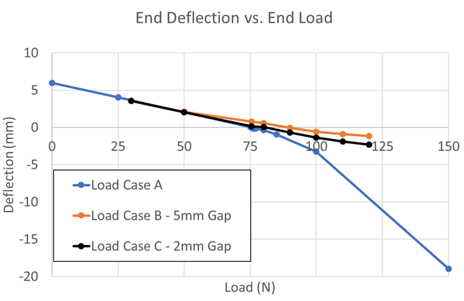
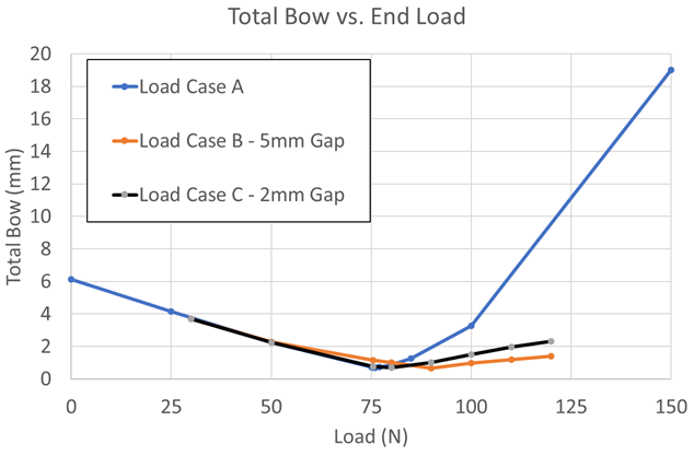
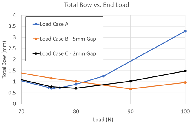
Figures 8 and 9 show the tip deflection versus load and total bow versus load, respectively, for Load Case A, Load Case B (5 mm gap distance), and Load Case C (2 mm gap distance). From the two plots, the lower dies for both cases, B and C, help control the deflection and bow very well. Upon first glance, it may seem as though they effectively control the distortion by the same amount. However, the length scale in the plots is millimeters. For larger parts, a few millimeters of distortion may be acceptable, but gear tolerances are generally in 10s, or possibly 100s, of microns. To get a better understanding at these length scales, the plot in Figure 9 has been reduced to loads between 70 and 100 N, with a subsequent rescaling of the total bow, as shown in Figure 10. It can now be seen in Figure 10 that there can be a difference of up to 500 µm between the three loading cases at a given load. Depending on how the processed gear is mated in the powertrain, one bow distortion may be preferable over another. It should also be noted that although the final values for the bow distortion are very similar for a 75.5 N load, the shape of the bow is drastically different, as seen in Figure 7. Heat-treatment simulation can help determine what distortion mode to expect after press-quench processing and aid in the design of better, more effective press quench tooling.
References
- A.C. Reardon, “Press Quenching,” ASM Handbook, Volume 4a, Steel Heat Treating Fundamentals and Processes, J. Dossett and G. Totten, Editors, ASM International, Nov. 2013.
- Justin Sims, “Modeling Can Improve Press Quenching Process,” Thermal Processing, October 2020, p 16 – 17.
- Z. Li, A.M. Freborg, B.L. Ferguson, P. Ding, and M. Hebbes, “Press Quench Process Design for a Bevel Gear Using Computer Modeling,” Proceedings of the 23rd IFHTSE Congress, April 18 – 21, 2016, Savannah, Georgia, USA, p 78 – 87.
- Zhichao Li, B. Lynn Ferguson, and Justin Sims, “Distortion Minimization of Bevel Gear Press Quench Hardening Process Using Computer Modeling,” Proceedings of the 30th ASM HTS Conference, October 15 – 17, 2019, Detroit, Michigan, USA, p 237 – 244.


 general practice for CQI-9 and AMS2750E")


