


Superalloy 718 is widely used for aerospace, nuclear, power generation, metal processing, medical, material processing, and chemical and petrochemical industries due to its excellent resistance to corrosion and high temperature deformation. Especially in aerospace application where materials see thermo and mechanical fatigue, the alloy is used for disk, seal, stator assemblies, diffuser/exhaust case, fastener, shaft, tube, impeller, etc. Enhanced elevated temperature property makes the alloy suitable for all types of welding/joining applications. The weldability property is paramount to parts manufactured via additive manufacturing processes, such as electron-beam, direct metal laser sintering, selective laser melting, and directed energy deposition, as an as-build part goes through a series of melting and resolidification during the build process. Fatigue testing is vital in understanding a material’s behavior as a factor of test conditions, manufacturing processes, and the ability to predict fatigue life.
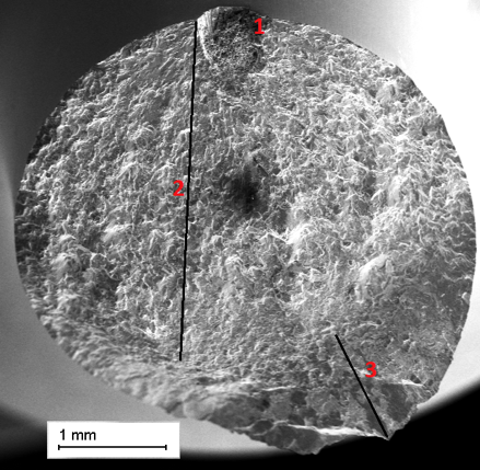
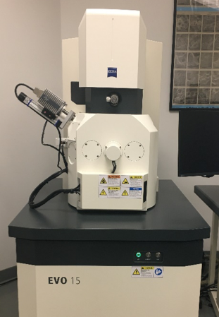
Fractography of a fatigue-fractured surface is important in identifying failure modes of a test specimen. It helps identify rate-controlling cause of crack initiation and its propagation mode. In most ductile failures, fatigued samples can have a primary crack initiation site and multiple secondary sites. In some cases, crack initiation is limited to a primary crack site. Fractography can be used to identify stable crack growth and crack overload regions as well. The primary crack site (1), stable crack growth region (2) and overload region (3) are shown in Figure 1. Fatigue striations or ‘beach mark’ can be measured to correlate crack length growth and potential drop. An optical microscope is used for low magnification characterization of a fracture surface. A scanning electron microscope (SEM) is typically used for higher magnification and detailed characterization of a fractured surface. Figure 2 shows Zeiss EVO 15, LaB6 SEM equipped with Bruker energy dispersive spectroscopy (EDS) and eucentric stage for better mobility of samples in the chamber. Semi-quantitative chemical analysis of inclusions is performed with EDS. The SEM has capability to image samples in the range of 10X – 100KX magnification. Regardless of technique used to image fracture surface, the ability to tilt the sample is key in better imaging and characterization of crack sites. Elemental mapping technique in EDS is used to locate the concentration and distribution of elements present in inclusion and surrounding area.
Understanding and characterizing the crack initiation sites aids in better design and processing of additive manufactured parts as they have anisotropic materials behavior. Balachandramurthi et al. reported electron beam powder bed fusion manufactured and post-treated alloy had better low cycle fatigue life in build direction compared to transverse direction [1]. The anisotropic behavior was primarily due to difference in the material’s yield strength. Reduced fatigue life in additive-manufactured samples can be attributed to lack of fusion, presence of precipitates, voids, grain distribution, and surface defects. Study conducted by Homberg et al. has shown four-point bend fatigue-tested samples to have higher fatigue life with smoother surface finish [2]. A rougher surface acts as a sea of stress concentration sites and at times coupled with grit embedment, fatigue life can be significantly reduced. A heat-treated and machined sample tends to have better fatigue life compared to as-built samples. Partial least square model has been used to establish correlation between fatigue life and surface finish [2] as such:
 K1-4 are various constants; S1 and S2 are surface roughness parameter; is the X-ray diffraction peak.
Given fatigue properties of different batches of selective laser melted as-built samples were similar, Balachandramurthi et al. predict that the surface roughness may have a greater effect than microstructural effects [1]. This finding points to the need for better surface preparation and points to possible defect sites. Apart from microstructural effect, test parameter like fatigue frequency also plays a role in the state of fracture mode. Generally, it is established that transgranular failure and oxidation/intergranular mode is dominant in high-frequency and low-frequency tests, respectively.
Nishijima et al. used a crack initiation area to estimate the fatigue limit of material [3].
 Fatigue life can be attributed to multiple factors, such as materials property, grain size, surface conditions, test environment, stress conditions — a ratio
 ![]() , mean
, mean ![]() , etc. A material’s grain size inverse correlation to its tensile property, which in turn has direct correlation with the fatigue strength. The Hall-Petch relationship
, etc. A material’s grain size inverse correlation to its tensile property, which in turn has direct correlation with the fatigue strength. The Hall-Petch relationship
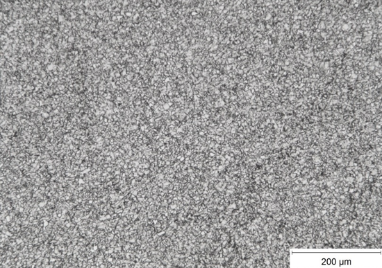
 shows the inverse relation between yield strength (σy) and grain size (d), where σ0 and ky are constants for a specific material. For a high reversal stress cycle fatigue of R = -1, Nishijima et al. showed the relationship between fatigue and tensile strength as σL (R= –1) = 0.5 σy [3]. With higher density of grain boundaries, fine-grained materials are highly effective in disrupting dislocation flow compared to coarse grain structure. A fine-grained Alloy 718 with ASTM grain size 10 with twinning is shown in Figure 3. In addition to fine grain structure promoting higher strength, FCC structure of austenitic superalloy promotes twinning, which impeded dislocation flow and is highly effective in blocking slip.
In fatigue tests, a crack can initiate at the surface due to a surface defect because of machining or prevalence of inherent material defect, see Figure 1. Spot 1 in the figure shows an inherent material defect on the surface that extends inward. For these defect types, crack initiates at the defective site as a result of high stress concentration and propagates from there. Sample machining and manufacturing processes — both traditional and additive must be optimized to minimize/eliminate surface defects.
Cracks can also initiate from an inclusion, which can be located at the surface or subsurface or internally. Figure 4 shows an inclusion on the surface of a specimen that was the primary crack initiation site. Typical inclusions in Superalloy 718 are Nb- and Ti-based, such as NbTiC, NbTiN, TiNbN, TiNbCN, TiNbS, TiNbSC, NbTiMoWCrC, etc. Grain size and their distribution also impact crack initiation. Materials with multimodal grain distribution and as-large-as grain structure are prone to grain failure, which act as crack initiation sites. Materials with multimodal grain distribution have high degree of microstructural misfit that act as microstress concentration sites.
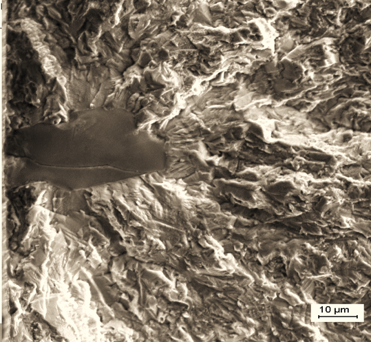
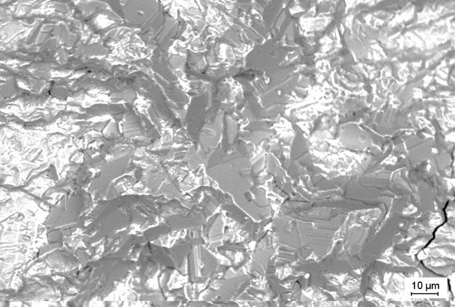
A fractured surface with coarse grain as primary crack initiation site is shown in Figure 5. The micrograph shows a mixed trans and intergranular failure mode. Fatigue fracture in Superalloy 718 are trans or intergranular in nature, see Figure 4 for a transgranular fracture. Belan et al. reported transgranular ductile failure with striations in 718 alloy with ASTM 12 grain size which was three-point fatigue tested at room temperature with static pre-load of -15 kN and dynamic force in the range of 6.31 – 12.8 kN [4]. Gopikrishna et al. [5] observed that high cycle fatigue life increased in finer grain sizes for both smooth and notch specimens tested at room temperature and 650oC. Thus, the morphology of fractured surface appeared transgranular in nature. These findings shed some light on the state of materials’ microstructure at the time of failure.
References
- A.R. Balachandramurthi, J. Moverare, N. Dixit, and R. Pederson, Mater Sci Enr A 735 (2018) 463- 474
- J. Holmberg, A. Wretland, P. Hammersberg, J. Berglund, A. Suarez, and T. Beno, Int J Fatigue 144 (2021) 106059
- S. Nishijima, A. Ishii, K. Kanazawa, S. Matsuoka, and C. Masuda, Fundamental fatigue properties of JIS steel for machine structural use. National Research Institute for Metals, NRIM Materials Strength Data Sheet Technical Document, No.5, 1989.
- J. Belan, A. Vasko, L. Kucharikova, and E. Tillova, MATEC Wed of Conferences 157, 07001 (2018)
- D. Gopikrishna, S.N. Jha, and L.N. Dash, “Influence of Microstructure on Fatigue Properties of Alloy 718,” Superalloys 718, 625, 706 and Various Derivatives, TMS, 567-573, 1997.


 general practice for CQI-9 and AMS2750E")


