


As discussed in the September/October 2016 Metal Urgency column [1], carburizing is a nonsteady-state diffusion process and thus can be expressed by Fick’s second law. For simplicity, when diffusion coefficient D is considered to be independent of carbon content (equal to carbon potential) and some practical boundary conditions are specified, the diffusion equation can be solved and the carbon concentration at any time and position can be determined when base metal carbon content C0, carbon potential Cs, and diffusion coefficient D are known. In manufacturing, it is more convenient to establish the relationship between effective case depth (ECD) and carburizing time t. This can be directly derived from the aforementioned solution, which can be expressed as:
 Equation 1
where:
x is ECD, k is carburizing factor, which is determined by several parameters including C0, Cs, and D, which is a function of carburizing temperature T.
Obviously, under certain carburizing conditions, i.e., when k is given, the necessary carburizing time t can be easily determined based on target effective case depth x. It seems that the task is simple: Determine k values under given carburizing conditions (carburizing temperature, carbon potential setting, and carbon content of the workpiece). Once k is determined, t can be calculated directly from Equation 1.
It should be noted that Equation 1 is valid only when all conditions are fixed, i.e., temperature and carbon potential should keep constant during the whole carburizing process. This is rarely true for most carburizing facilities. As mentioned in previous columns, the carburized part needs to be quenched into the appropriate quenchant so that the austenite will transform to martensite. In order to minimize the quench stress and distortion, the temperature of the part should be lowered before quenching. In this case, Equation 1 is not valid, as k changes with temperature.
Another bigger issue is the carbon and hardness profile within the case. In the gear industry, many gears need to experience post-carburizing processing such as grinding. If carbon potential keeps constant, the carbon content and hardness of the part drops quickly in the case. As a result, the remaining surface carbon content after grinding could be too low, which gives rise to soft surface (less than 55 HRC or 58 HRC depending on the rating) and the part cannot be used. This indicates that carburizing parameters (temperature and carbon potential) need to be adjusted such that the carbon and hardness profile in the case are flat and provide sufficient grinding stock removal. In other words, an optimized carburizing process should be set up to obtain an ideal carbon/hardness profile and to achieve minimized quench stress and distortion. Unfortunately, this makes Equation 1 invalid. Obviously, it is imperative to establish an optimized carburizing scenario, yet Equation 1 can still be used to predict the carburizing time based on the required effective case depth.
Carburizong Optimization
One practical way to get a flat profile of carbon and hardness is to set variable carbon potentials at carburizing temperature, i.e., set high carbon potential at the first stage and lower it at the second stage. Correspondingly, the first stage is called the boost phase, while the second stage is called the diffusion phase. The purpose of the boost phase is to expedite the carbon diffusion (shorten the cycle time), while the purpose of the diffusion phase is to adjust (flatten) the carbon and hardness profile. As discussed in previous columns, the highest carbon potential is limited by the maximum dissolved carbon content in austenite at the corresponding temperature to prevent potential carbide network. Typical carbon potential should be roughly 0.90 wt.% to 1.40 wt.% at 1,600°F to 1,800°F. For the diffusion phase, the carbon potential usually is set about 0.20 wt.% lower than that at the boost phase.
After carburizing, the temperature is lowered to slightly above Ac3 temperature (e.g., 1,500°F to 1,550°F) to reduce the quench stress and distortion. Correspondingly, the carbon potential is also lowered to around 0.80 wt.% in order to reach the 0.65 wt.% to 0.95 wt.% range required by AGMA standard.
Thus, the total carburizing time is the summation of three stages: boost, diffusion, and pre-quenching, i.e.:
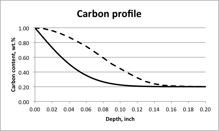
Here, tb, td, and tq refer to the amount of time at corresponding stages; tq is usually about 14 hours depending on the size of the part. Past carburizing data shows that when tb is three to five times of td, the obtained carbon/hardness distribution in the case is satisfactorily flat. In comparison, Figure 1 illustrates carbon distribution within the case for a single potential carburizing process and an ideal carbon profile that offers adequate case depth for grinding. The carbon profile obtained by setting tb = (3 – 5)td is in between these two curves. Historical data have revealed that the ratio of depth from the carburized surface to the location where 58 HRC is reached to effective case depth (i.e., from the surface to the location where 50 HRC is reached) is always more than 40 percent. This allows enough stock removal for grinding.
Effective Case Depth Precise Control
By setting the boost and diffusion phases and corresponding time allocation, a flat hardness profile can be reached. Lowering the temperature before quenching minimizes quenching stress/distortion or potential cracking. These two measures optimize the carburizing process and meet both heat treatment and manufacturing requirements. However, since neither carbon potential nor carburizing temperature is constant, the required conditions for Equation 1 to be valid are lost. This implies that mathematically, there is no functional solution for Fick’s second law. In other words, a similar expression to Equation 1 cannot be obtained. This makes it theoretically impossible to predict the necessary carburizing time for the part.
To solve this problem, we need to further simplify the model by ignoring some effects (such as the effect of alloying elements, grain size, and hardenability on carbon diffusion) and excluding the diffusion during carbon potential or temperature transition. This way, the whole carburizing cycle can still be considered as a single carbon diffusion process at boost temperature, except that diffusion time before quenching should be converted to an equivalent time at the boost phase, as the diffusion coefficient is smaller than that at boost temperature. This can be reached by multiplying an equivalent factor a, which equals to the ratio of the diffusion coefficient at the temperature before quenching to that at the boost phase. The calculation shows, depending on the temperature before quenching (1,500°F to 1,550°F), factor a can be any value in the range of 0.13 to 0.70 (depending on boost temperature between 1,600°F to 1,800°F). Correspondingly, the total carburizing time will be:
In order to solve the diffusion differentiation equation, carbon content at 50 HRC should be determined. Historically, this was considered to be 0.40 wt.% for carbon and low-alloy steels. Today, with more alloying elements added to the steels, i.e., to medium-alloy and high-alloy steels that are commonly used, this carbon content decreases. Per the literature, this content is in the range of 0.30 wt.% to 0.40 wt.% depending on the specific steel. This can be determined by experiment. For example, it was reported that carbon content at 50 HRC for SAE 9310 (nominal base carbon content of 0.10 wt.%) and SAE 4320 (nominal base carbon content of 0.20 wt.%) are 0.33 wt.% and 0.35 wt.% correspondingly [2].
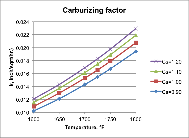
Based on this simplification and measured carbon content at 50 HRC, the diffusion equation can be solved and functional expression can be obtained similar to Equation 1. For a specific steel with base carbon content of C0, preset carbon potential Cs, carburizing temperature T (at the boost phase), and carbon content C at 50 HRC, carburizing factor k can be calculated. Figure 2 shows results for base carbon content of 0.10 wt.% at different carbon potentials and temperatures with carbon content of 0.33 wt.% at 50 HRC. It demonstrates that k increases with carbon potential and carburizing temperature.
Once k is determined, the total carburizing cycle time t can be determined based on required effective case depth per Equation 1. As long as the carburizing parameters are under control, the target ECD range can be reached precisely. Based on the total cycle time, the time at each phase can be allocated by Equation 3 and setting tb = (3 – 5)td. This has been proven by numerous carburizing test data of different steels. For example, for SAE 9310 and SAE 4320 with ECD of 0.025 inch to 0.300 inch, which covers much of the industry application range, by setting different carbon potential and using different furnaces, the relative error of the carburizing factor between the calculated value and that through statistical regression of the real tests is consistently less than ± 5 percent and the hardness profile is satisfactorily flat [2]. This indicates that the methodology proposed in this column provides both practical carburizing optimization and precise control of effective case depth.
Furthermore, this methodology has several advantages over the traditional way in determining the carburizing factor. First, the traditional way applies to plain carbon and low-alloy steels, as it assumes carbon content at 50 HRC to be 0.40 wt.%, therefore cannot apply to medium- or high-alloy steels. Second, it allows temperature change only, i.e., carbon potential keeps constant (close to the maximum dissolved carbon content in austenite at the corresponding temperature). To obtain the carburizing factor, one either needs to multiply a factor (typically 0.6 to 0.7) to the calculated carburizing factor of total effective case depth or use a table based on the cumbersome conversion. On the contrary, this methodology provides a straightforward equation to calculate k that allows changes with any or all carburizing parameters (such as temperature, carbon potential, and base metal carbon content). Finally, the carburizing factor determined by this methodology is more accurate than that determined by the classical way, as the latter usually gives three-decimal digits yet the former offers four digits. This higher accuracy provides cost savings and shorter lead times, especially for those parts with thick case depths, which take days of carburizing cycle time.
References
- M. Li, Carbon Diffusion and Carburizing Parameter Selection, Thermal Processing, September/October 2016, p. 18.
- M. Li, Practical Approach to Determining Effective Case Depth of Gas Carburizing, Gear Technology, March/April 2016, p. 56.


 general practice for CQI-9 and AMS2750E")


