


As anyone who reads this column knows, I’ve been doing this — working in the metallurgical and heat-treating business — for a long time, and occasionally I like to give readers a look into what went on in decades past, namely the 1970s.
Following are descriptions of a few projects that occurred in the lab that possessed some very unusual equipment in the decade of the early 1970s.
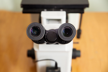
The first episode involves a “hot stage metallograph.” Anyone who has worked in or around a metallurgical lab knows a metallograph, as it was known then, is a glorified microscope designed to view polished and etched metallurgical samples, micros, of metal at high magnification. Today, they resemble a simple microscope seen at any high school or college lab. But back then, a metallograph was an elaborate device that occupied an entire desk top maybe five feet long. It consisted of the microscope with five objectives of different magnifications, generally 5x, 10x, 20x, 50x, and maybe a 100x. These, in combination with a 10x eyepiece, multiplied the objective mag by ten, i.e. 50x, 100x, 200x, 500x, and 1,000x. Plus, there was a system of optical filers to reveal different characteristics of the microstructure. Chemical etches such as ‘Nital,’ a mixture of 3 percent nitric acid in methanol (methyl alcohol), were used. This is a commonly used etchant applied to reveal pearlite, martensite, and other ferrous alloy microstructures. As is done now, photos were taken for reports. However, today a digital file is created and emailed anywhere in a digital report.
Photos of the microstructure in the ’70s were taken with a Graflex Speed Graphic camera that used a spring-back holder for Polaroid P-55 single sheet 4 x 5 slide film packets. When the packet was slipped into the spring-back housing, the metal catch held the negative in place while you pulled the sleeve back out to a stop. This exposed the film sheet or negative to the lens optics. After the shutter was triggered, you pushed the sleeve back into the housing and flipped a lever that squeezed the packet of chemical over the film as you pulled the entire film packet out. The squeeze function spread the chemical developer over the exposed film sheet. After waiting about one minute, the packet covering sheet was pulled away and there was the picture. You then wiped the photo with a preservative. That’s how the standard metallograph of the day worked. A few years later, Polaroid created color film using the same method (but we had to wait five minutes for developing).
Back to the project: Since this was an R&D department, the interest was in furnace development for the time for iron carbide to go into solid solution in austenite. The only method used at that time was to heat and soak the specific alloy at varying times at temperature, and then make micros of each sample and compare the percentage of carbide remaining — unless you were fortunate enough to have a hot stage metallograph.
This device was a metallograph with a miniature vacuum furnace positioned above the magnifying objective. The bottom of the vacuum system had a quartz window through which you could observe the changes on the polished surface of a ¼” diameter x 3/8” high sample. The sample would be polished and etched so that the face facing the optics of the metallograph could be seen via a special Xenon light system.
The small sample was situated inside two opposing thin strips of molybdenum heating elements designed to form two semi-circles around the sample. Air was evacuated down to about 5 x 10⁻⁵ torr (6.5 x 10⁻⁵ millibar) with a roughing and oil diffusion pump where heating began. A small platinum/rhodium thermocouple was inserted in a hole drilled into the side of the sample. As the sample was heated and reached the appropriate temperature, the surface of the sample could be seen to change. It was difficult to interpret exactly what was happening because we couldn’t tell if the microstructure was changing or whether the etched surface was somehow causing an illusion. Having said that, the iron carbide particles did indeed seem to get smaller over an extended period of time with black outlines forming around the carbide with the carbide becoming smaller.
The next obstacle was how to document this experiment since video recording was only done with special cameras. We rented a Bolex 16 mm camera and set up a timer and solenoid triggering mechanism to create a time-lapse film to record the process over several hours through the optics system of the metallograph. It worked. Without a darkroom we couldn’t process the film ourselves, so we sent the film to an outside processing studio for development. Sixteen mm film wasn’t something you ran down to the nearest drug store or pharmacy. The time-lapse approach worked as long as the Rube/Goldberg timing arrangement continued through the night hours. Generally, it did and the result — as crude as it was — was beneficial.
Since the carbide project worked so well, martensite and its transformation became our next investigation. That dilemma became a task of cooling a steel sample fast enough to create martensite inside the vacuum system. 52100 steel was chosen as the steel because we thought the sample was small enough that we could cool or quench with nitrogen blasting directly onto the sample above the heating elements. Eventually, to find a faster quench, the nitrogen gas was first passed through a makeshift refrigeration system consisting of ice and water.
The same evacuating and heating procedure in the carbide project was again used here with the exception of the time-lapse process. Since martensite begins to transform instantaneously when the Ms temperature is reached, for 52100 steel it’s about 480°F (249°C) when quenched from 1,550°F (843°C). As we watched and filmed in real time, what we thought was the transformation was somewhat confusing. We observed what I described was analogous to popcorn popping. The etched surface of the sample began to change as in a time lapse video of water freezing on a thin surface, like a series of sudden fissures. My project cohort and I were at first perplexed but I personally couldn’t explain other than we were witnessing martensite forming. My cohort wasn’t so sure, but what else could it be? My memory of those events has dimmed to some degree since the 1970s but we for sure had fun in those days when R&D funding was pretty active.
Reference
My cohort in those days was Jim Conybear, my carpool buddy.


 general practice for CQI-9 and AMS2750E")


