


In this month’s column, I will discuss a method of estimating the required flow for a quench tank.
Agitation has a significant effect on quenching speed. It reduces the duration and stability of the vapor phase and increases the maximum cooling rate. Effective agitation is essential to ensure that optimum properties are obtained, to maintain circulation of quenchant around the parts, and to obtain uniform temperature in the bath.
Agitation can be provided by load oscillation, pumps, or impellers. With pumped circulation or propeller agitation, baffle or manifold arrangements are desirable to direct the flow of quenchant upward around the components.
While impeller agitation is easy to design, install, and maintain, it is sometimes difficult to add to an existing quench tank due to space limitations. In these circumstances, the introduction of pumped circulation through manifolds may be preferable.
Impeller-type agitators are designed to move large volumes of liquids at low head pressures. This is typically encountered in quenching operations. As a rule of thumb, an impeller mixer will move about ten times the volume that a centrifugal pump with the same energy [1].
A pump is designed to move liquids against a high static head. As such, they have a smaller discharge capacity for the same energy as an impeller. Pumps can provide proper quenching conditions. However, there must be enough in number, and properly positioned to provide proper quenching.
On small, low-production items, agitation can be accomplished by moving the part or a small basket or tray of parts through the quenchant by hand. Work pieces may also be driven mechanically with respect to the quenching medium. For example, shafts are sometimes rotated in the quenching medium to produce the effect of agitation. Propeller or pump agitation is more desirable, however, because it is more controllable and less dependent on the operator.
Compressed air is not recommended since it produces a non-uniform quench, accelerates the oxidation and aging of quenching oils, is likely to introduce water contamination and increase fire hazards, and can promote foaming in water-based quenchants.
The type of agitation selected is dependent on the type of parts being quenched, and the volume of the quenchant to be agitated. Selection is often based on economics and not proper quench tank design.
Agitation is critical for quenching uniformity and proper control of distortion. It reduces surface-to-surface thermal gradients and provides for uniform heat transfer and uniform flow throughout the workload. It wipes the vapor blanket from parts to achieve proper quenching and minimizes persistent vapor that is trapped in keyways or blind corners. Racking and agitation work together to provide low distortion parts.
As agitation is increased, the vapor phase becomes less stable, and heat transfer increases. In the nucleate boiling region, there is little effect. In the convection region, heat transfer increases with increasing agitation. This effect is more pronounced with straight oils than with accelerated oils.
Kavskii and Zhelokhovtseva [2] showed that non-uniform cooling, particularly in the martensitic transformation range, would result in quench cracking and high residual stresses.
The problem of achieving quench uniformity is that the flow through the quench tank and through the workload is non-uniform. It is the purpose of the designer to intelligently design the quench tank to achieve proper uniform agitation. First, it is necessary to determine the actual flow required through the quench tank, then determine how the flow is to be achieved, whether with pump or agitator. Finally, the placement of agitators and pump outlets and inlets needs to be determined, so that proper uniform flow around parts is achieved.
Estimating Required Flow
Typical velocities, not exceeding 0.5 m/s, are encountered in immersion by gravity. Intermediate velocities, ranging from 1.1 to 1.8 m/s are achieved in hand quenching. Spray quench rings are usually operated between 4.6 and 30 m/s but special applications sometimes use velocities as high as 150 m/s. In most applications, the typical agitation rates observed in commercial quench tanks are 0.25-1.5 m/s. This wide range of available fluid velocities in even similar type of quench tanks makes comparison of results in different operations, or even in the same plant difficult.
For most applications, a velocity of 0.5-1.5 m/s average flow velocity past the part is necessary for proper quenching. Generally, low density loads will require velocities of 0.5-0.75 m/s, whereas densely packed loads may require velocities greater than 1.0-1.5 m/s.
Determining the proper flow rate is one of the more difficult operations required for a quench tank. One method of calculating the necessary flow rate is by first determining the necessary velocity required for proper quenching. While this may require detailed quenching studies for precise calculation, simple approximations can be made.
The average desired velocity past the part is then multiplied across either a horizontal or vertical cross section of the quench tank (Figure 1), depending on what makes sense and whether a convenient plane of symmetry exists. In the case of Figure 1, only half the cross section of the quench tank was used, to provide for return flow to the agitator.
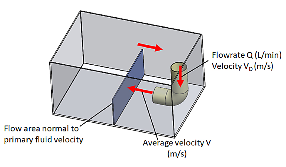
For integral quench furnaces, or sealed quench furnaces, it is usually convenient to take a horizontal cross section through the entire quench zone. This method is appropriate for determining the necessary flow rate for either pumps or impeller-type agitation. This average velocity value then translates into the necessary flow rate, Q up through the workload. Slight tank geometry changes can be tolerated provided the average fluid velocity past the part is maintained.
Once the necessary flow rate (m3/s or ft3/m) is determined, and an estimate of the number of pumps (or impellers) required is made, the flow rate per agitation unit (pumps or impellers) is determined. The number of agitation units is often based on economic reasons, pump availability, or size considerations.
Conclusions
In this short column, a method was described for calculating the necessary flow through a quench tank. In the next installments, we will discuss choosing pumps or impellers, and placement of the agitators.
Should you have any comments on this article, or suggestions for further columns, please contact the editor or myself.
References
- United States Steel, “Improved Quenching of Steel by Propeller Agitation,” United States Steel, Inc., Pittsburgh, PA, 1957.
- N. N. Kavskii and R. K. Zhelokhovtseva, “Optimum Cooling During the Quenching of Steel,” Izv. VUZ Chernaya Metall., vol. 3, pp. 111-113, 1982.


 general practice for CQI-9 and AMS2750E")


