


Residual stress is the stress that remains within a material or body in the absence of external loading or thermal gradients. The engineering properties of bearing components (e.g., dimensional stability, fatigue life, distortion, and wear resistance) can be significantly influenced by residual stress. For example, high-amplitude residual stress stored from heat treatment can increase the costs of subsequent machining, and the re-equilibration of the remaining residual stress can seriously distort the shape of bearing parts. As a result, the bearing industry is making an effort to closely monitor residual stress and minimize the generation of undesirable residual stress during the manufacturing process.
Generally speaking, there are two different types of residual stress that have been classified: macro/long range residual stress and micro residual stress. Macro/long range residual stress can scale over the entire body of a component and is much larger than the grain size of the material. Micro residual stress, on the other hand, exists at micron scale as a result of lattice strains, dislocations, and other crystalline defects.
Origin of Residual Stress
Residual stress can be developed through the simple quenching of a hot solid bearing part and its consequent thermal contraction. During the quenching process, the external surface shrinks first, while the internal core is still hot and counter-strained in the tensile direction. Next, the internal core material starts to shrink and is constrained by the rigid external surface that has already been thermally contracted. This leads to compressive residual stress at the material’s surface and tensile residual stress at the material’s core [1].
Aside from the residual stress induced by thermal contraction, phase transformation is another important source of residual stress in bearing materials. Austenite has a face-centered cubic (FCC) structure, which is more densely packed than body-centered cubic (BCC) ferrite. Therefore, a local volume expansion can be expected once the austenite is transformed into ferrite (without considering the thermal effects). Both martensite and bainitic ferrite have a body-centered tetragonal (BCT) structure, to which the addition of carbon atoms increases the degree of tetragonality (c/a axial ratio) and expands the BCT lattice volume compared to carbon-depleted ferrite. Such phase transformations can generate micro residual stress and affect the amplitude of macro residual stress.
Figure 1 schematically shows the residual stress distribution of two typical bearing industry products: case carburized bearings and through-hardened bearings. In case carburized bearings, the core first transforms during quenching from austenite to ferrite and martensite, with an attendant relaxation of any transformation stresses. Later, the high-carbon case transforms to martensite at a much lower temperature, inducing volume expansion. But the degree of expansion is constrained by the rigid core material. Therefore, residual compressive stresses are developed in the case, with their maximum at the surface, and residual tensile stresses are generated at the core.
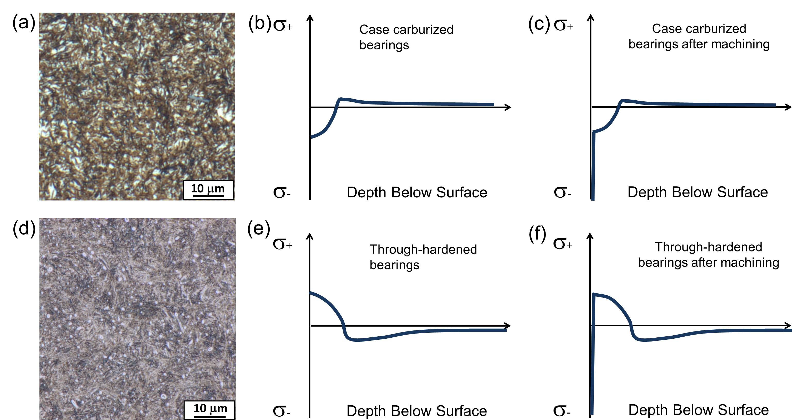
In actual practice, the exact maximum compressive residual stresses can be tens of microns away from the surface because the decarburizing layer at the surface contains large amounts of retained austenite. In through-hardened cases, hard martensite/bainite first forms at the surface of the bearing rings during the quenching process, along with the associated volume expansion, whereas the remaining parts in the center are still austenite. Later, the remaining austenite transforms to martensite/bainite, but its volumetric expansion is constrained by the hardened surface layers. This dimensional restraint produces compressive stress in the interior and tensile stress at the outer surface.
Multi Length-Scale Characterization of Residual Stress
Traditionally, macro residual stress is considered by engineers only when designing parts. However, the constituent microstructures of bearing products consist of micron- or even nanometer-scaled bainite, martensite, and carbide structures. Monitoring micro residual stress can be as important as monitoring macro residual stress because it provides direct guidance for optimizing thermal processing to alleviate the amplitude of the residual stresses formed during phase transformations. There are many different methods of residual stress measurement, as shown in Figure 2, in which the blue boxes represent destructive and semi-destructive methods. In general, the penetration depth of a single measurement can be sacrificed for the sake of higher spatial resolution.
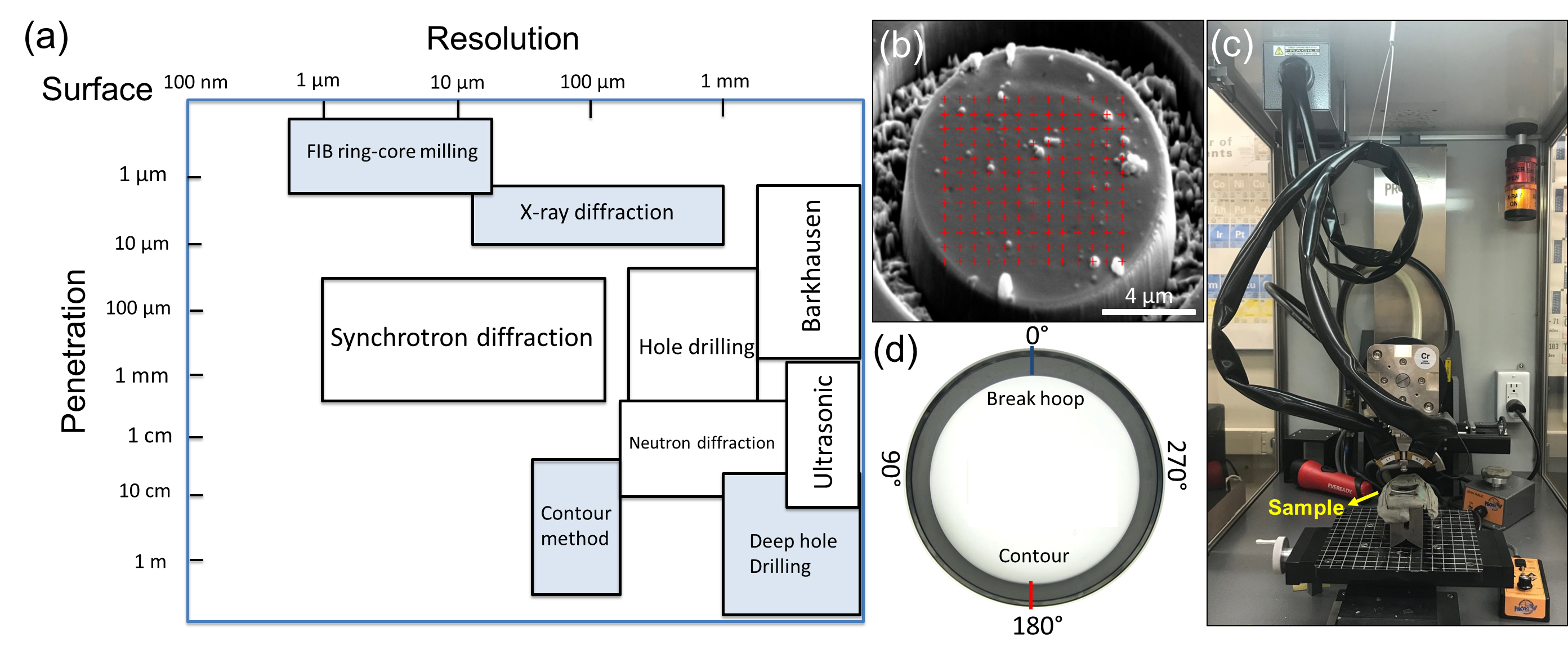
The focused ion beam (FIB) ring-core milling method provides site-specific residual stress measurement at micron scale [2]. This method requires an annular trench to mill the region of interest as a circular island (Figure 2b). Once the milling reaches sufficient depth, the residual stresses are completely relaxed. This induced relaxation strain is then measured by the position changes of pre-marked spots at the surface through the computed digital image correlation. Later, the residual stresses can be calculated by the relaxation strain using Hooke’s law.
Among the various methods of residual stress determination, diffraction-based techniques have been widely used to evaluate residual stress in crystalline materials. The elastic strain is determined by the change in the diffraction angle, 2θ, that reflects the change in the interplanar lattice spacing, d, from the stress-free state d0, according to Bragg’s law.
X-ray diffraction methods are generally available in regular metallurgy labs and also can be used for measuring both micro and macro residual stress (Figure 2c). However, the penetration depth of normal X-rays is limited to less than 10 μm, so the surface layers must be electro-polished many times to get a reasonable macro-scaled depth-dependent stress profile. The synchrotron X-ray provides much higher-energy X-rays, and the spot of the beam can be as sharp as 1 μm — making measurements with both good penetration depth (100 μm–3 mm) and high spatial resolution (1–100 μm) possible. Neutron diffraction techniques are similar to X-ray diffraction techniques, but the measuring depth can be varied from 0.2 mm for near-surface measurement to 25 mm in steels, thanks to the high-energy neutron beam [3].
The contour method determines residual stress through an experiment that involves carefully cutting a specimen on one side and measuring the resulting deformation due to residual stress redistribution on the other side (Figure 2d), a process based upon solid mechanics [4]. Residual stress is computed by measured displacement data through an analysis using a finite element model that accounts for the stiffness of the materials and part geometry. A spatially resolved map that describes the residual stress field at bulk scale can be generated with micron-scale resolution. This method is especially suited for complex, spatially varying residual stress fields that are difficult to evaluate using conventional point-wise measurement techniques such as X-ray diffraction [4].Residual stress monitoring creates both challenges and opportunities for the bearing industry, particularly because residual stress is not easily quantified or identified during the production process, but still has a direct impact on wear performance and fatigue life. It is expected that understanding and monitoring residual stress, and the generation of statistical data on residual stress, will help the bearing industry advance its development of bearing performance.
References
- A.K. Sinha, Defects and Distortion in Heat-Treated Parts, Heat Treating, Vol. 4, ASM Handbook, ASM International, pp. 601–619, 1991.
- N.S. Rossini, M. Dassisti, K.Y. Benyounis, A.G. Olabi, Methods of measuring residual stresses in components, Materials & Design 35, 572–588, 2012.
- M. Sebastiani, C. Eberl, E. Bemporad, G.M. Pharr, Depth-resolved residual stress analysis of thin coatings by a new FIB-DIC method, Materials Science and Engineering: A 528(27), 7901–7908, 2011.
- M.B. Prime and A.T. DeWald, “The Contour Method,” Chapter 5 in Practical Residual Stress Measurement Methods, G. S. Schajer, (ed.), Wiley-Blackwell, pp. 109–138, 2013.


 general practice for CQI-9 and AMS2750E")


