


Hardening, full annealing, and normalizing steel requires heating to a temperature that forces a lattice or crystal configuration change from body centered cubic (BCC) to face centered cubic (FCC) lattice called austenite or gamma iron. FCC lattice, in general terms, due to its larger atomic spacing, allows carbon via molecular diffusion to fill the lattice spaces. There is a limit to how much carbon the FCC lattice can hold, i.e. at 2,095°F, austenite will allow 2.03 percent carbon to diffuse into the lattice. As the temperature drops, the quantity of carbon the FCC lattice can hold also drops. For example, at 1,333°F, austenite will allow 0.80 percent carbon to fill the FCC spaces. As carbon saturates the austenite at a given temperature to the right of the Acm line on Figure 1, the iron-carbon equilibrium (Fe-C) diagram, it will precipitate as cementite or iron carbide (Fe3C) a very hard and brittle intermetallic compound composed of 6.67 percent carbon and 93.3 percent iron.
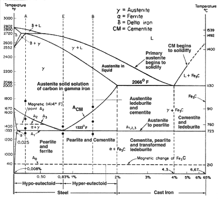
Practically speaking, the Fe-C diagram (Figure 1) is an isothermal — or time, (time for carbon to reach an equilibrium phase in iron) temperature, transformation (TTT) diagram — for iron and carbon only with no alloying elements. To find the microstructure for a particular carbon concentration, draw a line vertically up from 1-percent carbon until it intersects the Acm line. Then draw a horizontal line left to find the temperature. That temperature is approximately 1,415°F — which means if steel with 1-percent carbon cools below 1,415°F, carbon will begin to precipitate as iron carbide, Fe3C, reducing the percent carbon dissolved in the austenite matrix lowering the ultimate hardness the steel could achieve if quenched.
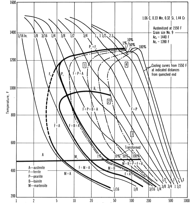
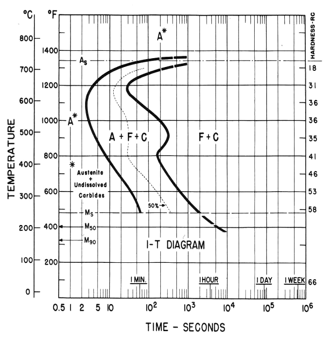
In the real world, the Fe-C diagram has more application to the theoretical relationship between carbon and iron since pure iron and carbon only is not a practical material, since manganese, silicon, and phosphorous are always alloyed with iron and carbon and affects the A1, A3 and Acm lines on the diagram. For true applied situations, the critical or continuous cooling transformation diagram (CCT) in Figure 2 is used to determine the products created by quenching. The TTT diagram in Figure 3 is used to predict the phases like lower bainite that will occur when the steel is isothermally held for a specific time and temperature such as austempering. Having said that, depending on the cooling rate below the austenite-forming temperature of 1,333°F (722°C), A1 line on the Fe-C diagram ferrous materials is often used as a guide to forecast the microstructures or phases based on the concentration of carbon atoms within the body centered cubic (BCC) lattice of iron. Carbon in solid solution within the austenite FCC lattice will determine the hardness level and alloying elements such as manganese, nickel, moly and others the depth of hardness when parts are quenched.
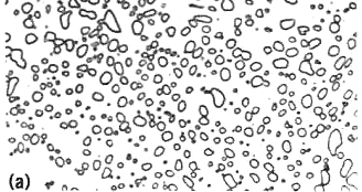
Carbon tied up as iron carbide Fe3C in the austenite matrix and not integrated into the FCC lattice cannot contribute to the martensite hardness. In order to achieve the maximum hardness, parts must be heated to as high an austenitizing temperature as possible that will not increase the grain size and lower impact strength. In addition, too much carbon dissolved in austenite will lower the martensite start temperature resulting in excessive retained austenite when quenched. A case in point is 52100 steel where the carbon level is always shown as 0.95 to 1.02 percent, but that is the total carbon and does not separate the carbon tied up as iron carbide. Every tiny iron carbide Fe3C particle seen in a photomicrograph of 52100 steel, Figure 4 actually contains 6.67 percent carbon.
I mention the matrix carbon to carbide carbon because the prior heat treat history has an impact on how the steel reacts during quenching or austempering. If the steel was isothermally held below the Acm line for an extended time, during a spheroidization process for example, more iron carbide would form, reducing the matrix carbon and thus reducing the maximum achievable hardness when quenched. Conversely, if the steel was austenitized at a higher temperature, say 1,800°F, more carbon would dissolve into austenite per the Acm line on the Fe3C diagram, increasing the quantity of retained austenite by lowering the Ms and Mf temperatures. Carbon in steel can come from two sources: It can be manufactured with a specific carbon throughout the material allowing it to be through hardened, surface to core, or a medium or low carbon steel can be carburized with endo gas producing a case-hardened product. Either way, the phases discussed earlier can apply to the carburized case as well as the part’s core.
52100 is a popular bearing steel because its hardness is achieved by martensite through quenching and, to some degree, by the excess iron carbide always present even after austenitizing. Iron carbide is a very hard, brittle material providing improved wear for bearing applications.
Many of the products made from 52100 will require cold forming and, due to the high carbon content, the material must be heat-treated to reduce the hardness — thus spherodizing is employed. Spherodizing involves first heating to above the Acm line to about 1,450°F (787°C), soak for five to seven hours, cool to 1,200°F (650°C) at 20°F (11°C) per hour until ambient. The ferrite matrix microstructure is very soft and provides a good prior structure for hardening.
52100 falls between a high carbon material and a low hardenability tool steel — tool steel in that much of its wear resistance comes from carbide as does tool steel like the M (molybdenum) and T (tungsten) high speed tool steels.
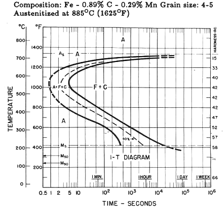
Because 52100 finds use as a bearing steel and has fairly low hardenability, it must be oil quenched when section sizes approach 1/4-inch diameter despite having 1.41 percent chromium and 0.020 percent nickel. Now, compare 1095 steel (actual carbon, 0.89 percent), Figure 5 that has no chromium or nickel: 1095’s martensite start temperature (Ms) is 410°F (210°C) where 52100’s is 465 °F (240°C). Generally, the higher the matrix carbon, the lower the Ms point but not in this case. Why? Likely it’s because the matrix carbon of 52100 is lower than 1095 for one major reason: chromium. As stated above, carbon higher than 0.80 percent will form iron carbide, but 52100 has an additional carbide former in chromium. Nickel as an austenite stabilizer also lowers the Ms but not in the case of 52100.
All of the above characteristics make 52100 an unusual material suitable for high hardness martensitic applications and austempering where the higher carbon content and chromium produce a harder, lower bainite microstructure.


 general practice for CQI-9 and AMS2750E")


