For decades, the gear industry has addressed the challenge to produce high-performance components in a cost-effective manner. To meet design intent, vehicle transmission components need to be heat treated. In many applications, the high demands regarding service life of components can be reached only by the application of a customized case hardening. This case hardening process results in a wear-resistant surface layer in combination with a tough core of the component.
Enhanced fatigue resistance of the components has become even more important. This is mainly driven by the need for weight reduction and by the introduction of higher durability claims. Some vehicle OEMs have introduced a 100,000-mile warranty for the powertrain.
When trying to improve fatigue properties, two important areas need to be addressed: improvements of material and improvements in heat treatment technology. This paper describes the advances in these fields over recent years.
Improved Material
Traditionally, gear components are made of case hardening steels such as 8620H, 8625H, 5120H, 5130H, 9310H, 16MnCr5, 20MnCr5, 27MnCr5, 18CrNiMo7-6, and others. The chemical composition of a steel grade defines its hardenability — with the most important elements being carbon, manganese, chromium, nickel, boron, and molybdenum. The hardenability of a steel grade can be quantified either with “DI-values” or with “Jominy-curves.”
The use of DI-values is popular in North America. DI (ideal diameter) is the largest diameter of a given steel composition that, under maximum quench conditions, still reaches 50-percent martensite in the core [1]. This means that a high DI-value corresponds with a good hardenability of the steel.
The use of Jominy-curves is popular in Europe. The Jominy hardenability curve is a standardized test as described in ASTM A255 [2] using cylindrical specimen with Ø25 mm and 100 mm height as test probes. After austenitizing, the probe is hung vertically and quenched with a water jet of well-defined intensity. The water jet is directed toward the lower face of the cylindrical specimen. This means that with increasing distance from this face, the quench rate inside the probe is continually reduced.
After completion of the quench, the hardness profile is measured in an axis-parallel line with 0.4 mm distance to the surface. The resulting curve is called the Jominy-curve. This curve describes the relation between the distance from the lower face of the probe in millimeters or in 1/16 of an inch (called the Jominy-value) and the achieved hardness in HRC. Besides the experimental method as earlier described, the curve can be calculated from the chemical composition of the steel grade as well. Figure 1 shows typical Jominy-curves of case hardening steels.
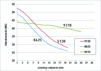
Each standardized steel grade has a defined range of hardenability, meaning that each grade has a minimum and maximum Jominy-curve. However, many producers have restricted this range further. Doing so will result in the following benefits:
- Improved distortion control
- Reduced variation of core hardness and case hardening depth (CHD) after heat treatment
- Reduced variation of microstructure (e.g., avoiding bainite formation in the surface area) after heat treatment
Over recent years, in many applications the hardenability range was restricted to the upper end of the standard range. The tightest range, which can be supplied by the steel industry today, is a band of 4 HRC. Figure 2
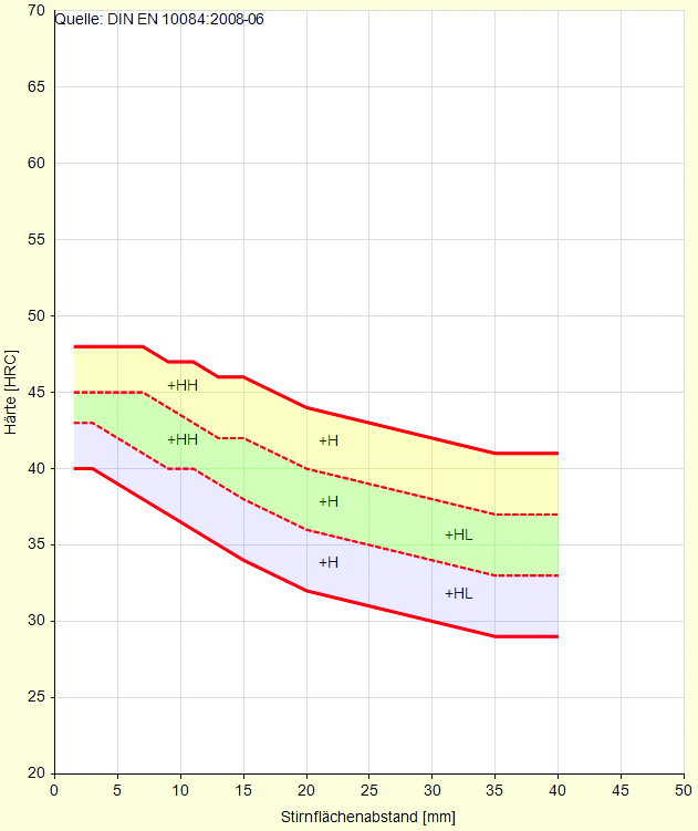
shows an example of the grade 18CrNiMo7-6 with the standard range and with the restricted hardenability. The HH-grade (high hardenability) has a range of hardenability that is restricted to the upper third of the standard range.
In the following three examples, successful restrictions of hardenability are given.
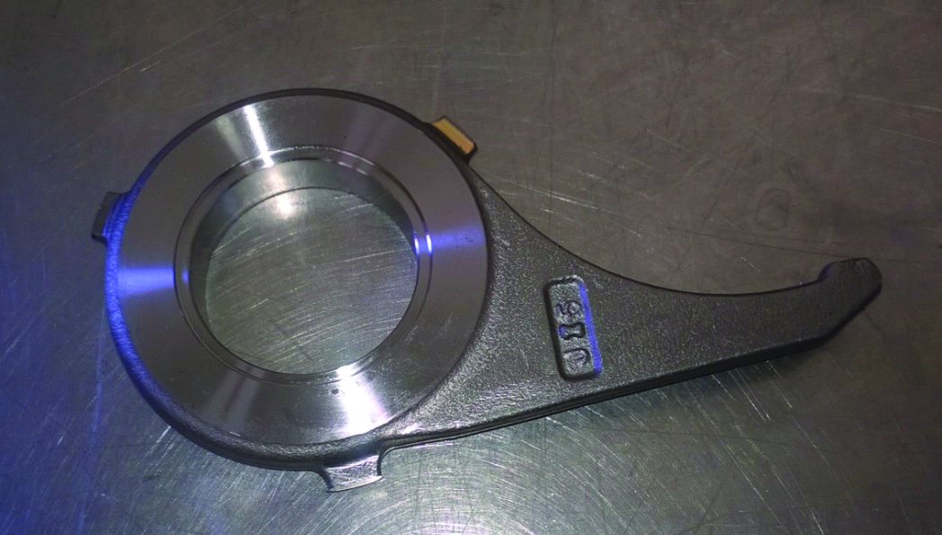
Levers made of 8620H material were initially supplied using the standard range with a minimum DI = 1.7 inches (see Figure 3). This resulted in significant variations of core hardness and case hardening depth. After restricting the material to a minimum DI = 2.6 inches, these variations were minimized and a consistent quality was achieved after heat treatment.
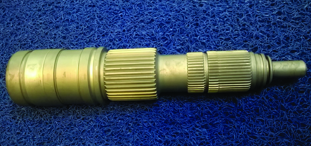
Shafts made of 28MnCrB7-2 material were initially supplied in a rather wide range of hardenability with DI = 2.2 to 3.4 inches (see Figure 4). This led to significant variations in core hardness and resulted in problems achieving consistent microstructure after heat treatment. After restricting the hardenability to a range of DI = 2.7 to 3.1 inches, those variations were eliminated successfully.
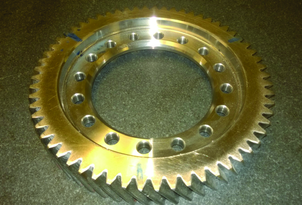
Final drive ring gears made of 4121M material were initially supplied with DI-values ranging from 2.7 to 3.1 inches (see Figure 5). This led to significant variations in core hardness. After improving the hardenability to a range of DI = 2.9 to 3.3 inches, those variations were reduced and core hardness specification (28 HRC min.) was safely reached.
Advanced heat treatment technology
The high demands regarding service life of transmission components for most applications can be reached only by the application of a customized case hardening. This case hardening process results in a wear-resistant surface layer in combination with a tough core of the component. Over the past 15 years, the technology of low pressure carburizing (LPC) and high pressure gas quenching (HPGQ) was established in serial production. LPC is often referred to as vacuum carburizing. Typical applications include gear parts, machine components, and bearing components, as well as injection systems for engines.
The LPC process takes place in a pressure range between 5 mbar and 15 mbar and a temperature range between 870°C and 1050°C. In most cases, the carburizing temperature is between 940°C and 1000°C. During the complete process, the treated components are not exposed to any traces of oxygen [3].
Figure 6 shows the LPC process in a schematic diagram. First, the charge enters the furnace chamber under vacuum, followed by convective heating under a nitrogen atmosphere close to 1 bar. Convective heating offers a quicker and more homogenous heating of the load compared to vacuum heating alone. Subsequently, another heating phase under vacuum takes place. The actual carburizing and diffusion starts after all parts have reached the specified carburizing temperature. Carburizing takes place by applying a routine of alternating pulses and diffusion steps. Acetylene is used in most applications as the carbon source.

Once the targeted carbon profile is obtained, the parts are quenched. Quenching can be initiated either from carburizing temperature or from a lower hardening temperature. In most cases, HPGQ with either nitrogen or helium is applied after LPC [4]. In a few applications, oil quenching is applied after LPC.
The high mass transfer of carbon into the components during LPC leads to significantly shorter treatment times compared to conventional gas carburizing (see Table 1).
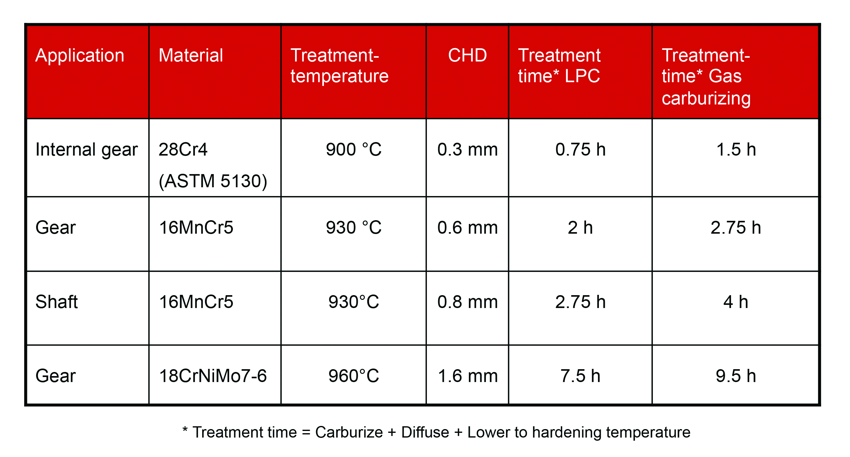
When combining LPC with HPGQ, the process provides the following advantages compared to gas carburizing combined with oil quenching:
- Excellent carburizing homogeneity even for components with complex shapes
- Avoiding intergranular oxidation (IGO) and surface oxidation
- Shorter cycle times
- Potential for further reduction of cycle time when applying high temperature LPC
- Possibility to integrate heat treatment into the production line [5]
- No conditioning of the equipment necessary (meaning no stepwise heating-up and no saturation of the furnace insulation necessary)
- Clean surfaces of parts after heat treatment and no washing of parts necessary
- Environmentally friendly process (small consumption of resources and no disposal of oil or salt bath residues)
- Potential to reduce heat treat distortion [6]
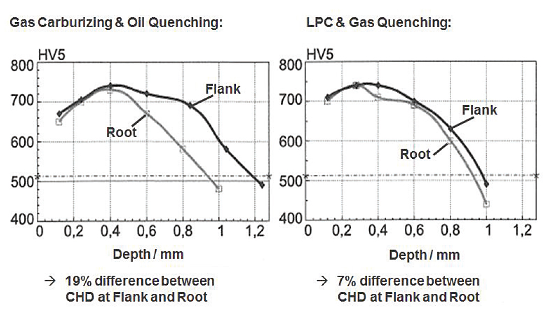
Altena studied, in particular, the field of carburizing homogeneity. Figure 7 shows the hardness profile after LPC and HPGQ compared to gas carburizing and oil quenching [7]. When using LPC and HPGQ, the hardness profile at the root is almost identical to the profile at the flank.
Carburizing temperature and microalloyed steel grades
The costs of the heat treatment process are largely driven by the cycle time. As shown in Table 1, the high-mass transfer of carbon into the components results in significantly shorter treatment times of LPC compared to atmospheric gas carburizing. The advantage of LPC can be further enhanced by increasing the carburizing temperature. With increasing carburizing temperature, the diffusion rate rises sharply, thus carburizing time is significantly reduced (see Figure 8).
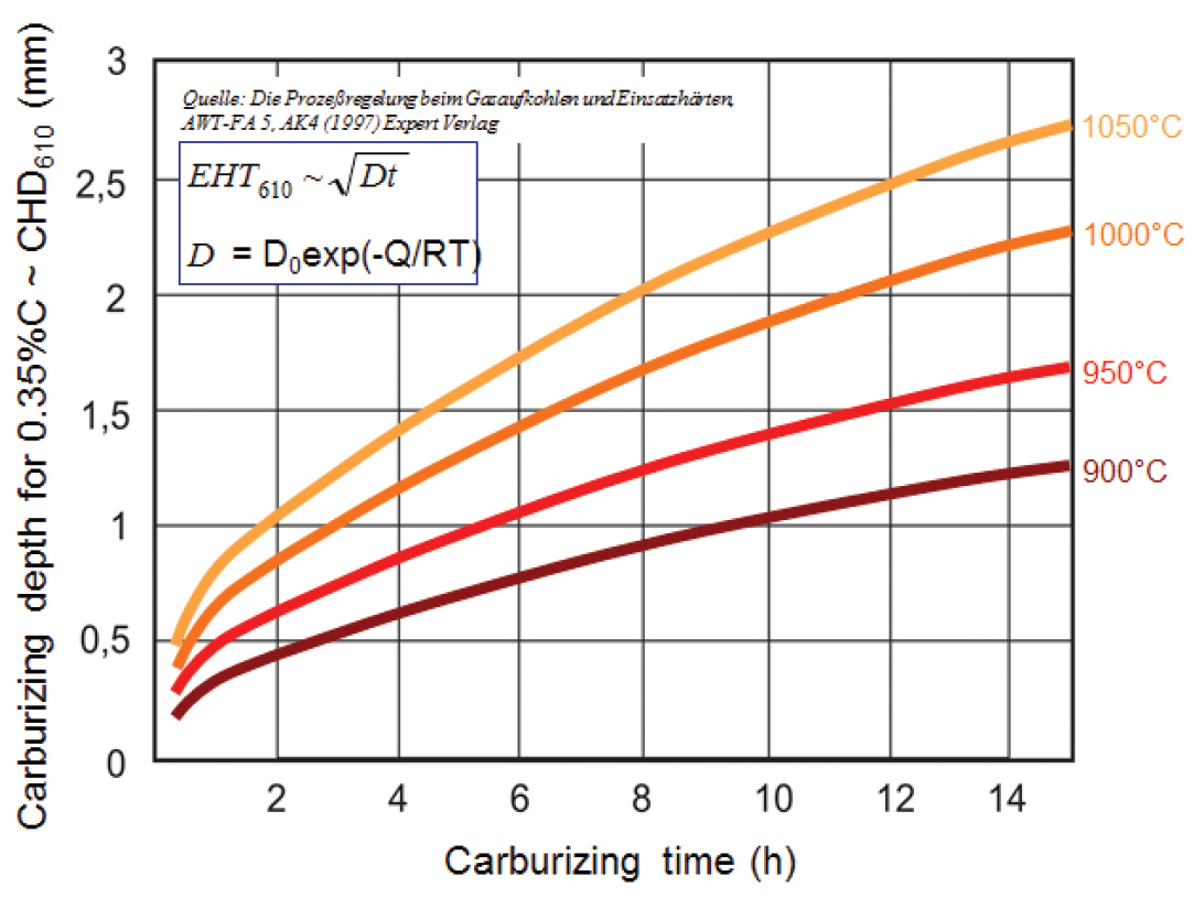
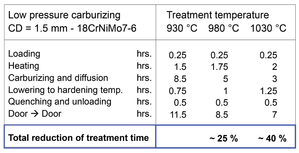
Table 2 illustrates the treatment times for LPC of 18CrNiMo7-6 at different temperatures for a case depth of 1.5 mm. It shows that the total process time is reduced by 40 percent if carburizing temperature is elevated from 930°C to 1030°C.
The potential for improvement is increased with higher case depth requirements. For material 15CrNi6 and a case depth of 3 mm, for example, a total process time reduction of 55 percent was verified when the carburizing temperature was increased from 950°C to 1050°C [8].
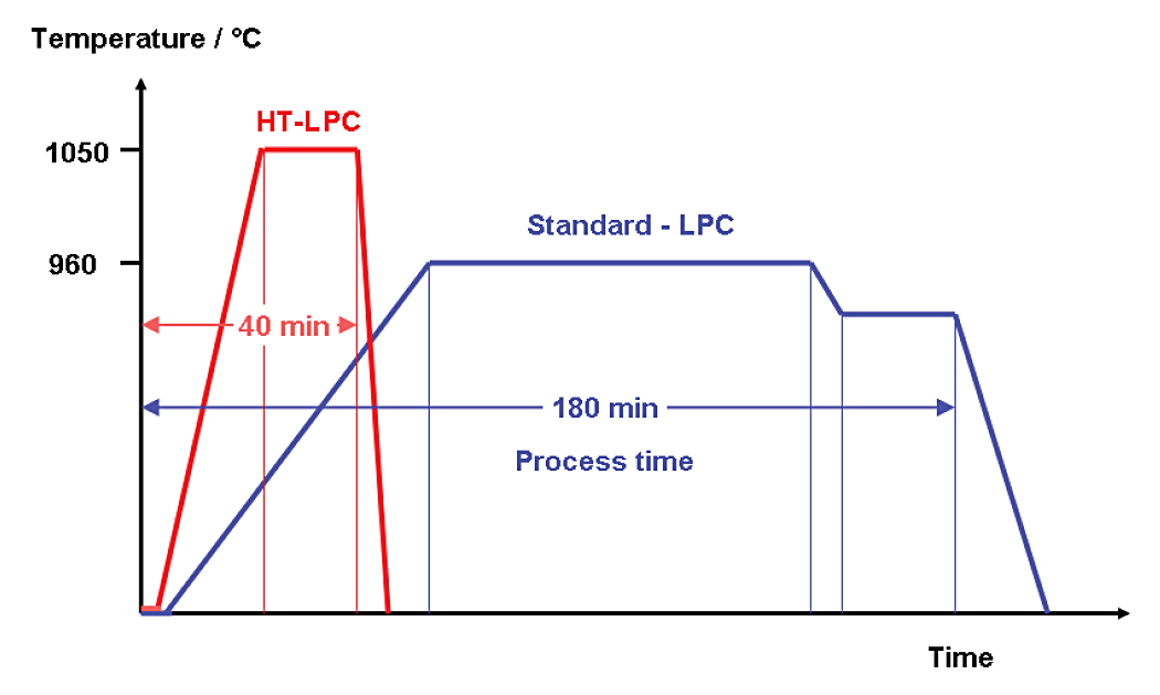
Over recent years, the carburizing temperatures rose steadily (see Figure 10). This led to enormous cost reductions and dramatic savings of energy.

However, when using today’s conventional case hardening steels, there are limitations. When applying high carburizing temperatures above the range of 980°C to 1000°C, this may lead to an unwanted grain growth. Components with coarse or mixed grains have the following disadvantages:
- Higher macroscopic heterogeneity
- Less toughness, especially in the carburized area
- Lower tooth root bending strength
Especially for dynamically loaded parts, the formation of coarse grains can reduce service life substantially. As a countermeasure, steel suppliers started several years ago to develop new microalloyed steel grades to prevent unwanted grain growth [10, 11]. These microalloying elements form precipitates during the steel production process that act as grain boundary pinning particles and thus inhibit abnormal grain growth during heat treatment at high temperatures.
For high temperature carburizing up to 1050°C, such steels often have a controlled amount of nitrogen, N (120–170 ppm) and aluminum, Al (250–350 ppm). Furthermore, a small amount of niobium, Nb (320–400 ppm) is being added to the steel. The steel production process route is controlled in a way that an optimum size and distribution of the Al(N) and Nb(C,N) precipitates are being secured. Several microalloyed steel grades have been developed and successfully tested jointly by steel suppliers and gear manufacturers [12, 13].
Currently, several gear manufacturers are in the process of adjusting their material specifications to use these materials in high temperature heat treatment. No negative influence of micro-alloying on the gear machining processes has been reported.
Furthermore, the material needs to have a sufficient and controlled hardenability to allow for quenching with moderate quench intensities. High quench intensities should be avoided to facilitate a cost-effective gas quench process. Typical steel grades suited for that process are 20MnCr5-HH, 23MnCrMo5, 27MnCr5, 18CrNiMo7-6 or 20NiMoCr6-5, 5120, 5130, or 9310.
The use of microalloyed materials is necessary to exploit the vast potential of process time reduction through high temperature carburizing by means of LPC.
Improvements in fatigue resistance
Figure 11 illustrates the stress distribution on running gears. The highest stress appears at the flank and the root of the teeth.


One popular test method to quantify tooth root fatigue is the Imbalance-Excited Resonance Pulsator — also called the Pulsator test. Figure 12 shows the setup of the test rig.
The tested gear is part of a mechanical oscillation system with a sinusoidal load applied. The components are tested with different loads, and as a result, the S/N curve (Wöhler curve) is generated. This curve assigns — for a certain failure probability — the achievable number of load cycles to each load level.
The German drivetrain research association (FVA) has determined S/N curves in order to compare test gears heat treated with gas carburizing and oil quenching and test gears treated with LPC and HPGQ [14]. These S/N curves were determined by using the Pulsator test. The components were not shot-peened. Figure 13 shows a comparison of the tooth root bending strength in the range of limited fatigue life at N = 3 · 104 load cycles for 50-percent failure probability. Two different materials were tested. For both materials 20MnCr5 and 18CrNiMo7-6, the gears treated with LPC demonstrated higher bending strength than the gas carburized ones. When comparing the gears made of 18CrNiMo7-6 treated with LPC at 940°C with those treated at 1050°C, the later ones showed significantly lower strength. This can be explained with the grain growth that occurred during treatment at 1050°C. The test gears were made of a standard grade without microalloys, therefore, formation of large grains was not avoided.


A summary of the tooth root endurance limit as a function of the carburizing method and the carburizing temperature is given in Figure 15. Clearly, the LPC-treated gears demonstrate higher tooth root endurance limit (meaning strength against tooth break at the tooth root) compared to gas carburized gears. When analyzing pitting on the tooth flank, the same results were obtained when comparing LPC-treated and gas carburized test gears [14].

Conclusion
Improvements in heat treatment technology and improvements of material are key factors to enhance the fatigue resistance for gear components. A clear trend toward a restriction of hardenability of the steel and an increase of hardenability of the steel could be observed over recent years. As a result, the variations in core hardness and case hardening depth (CHD) after heat treatment were significantly reduced. Another important benefit when restricting material hardenability is an improvement of distortion control, which was described in earlier publications.
The application of advanced heat treatment technologies such as LPC in combination with HPGQ offers many benefits. One of them is an enhancement of tooth root bending strength compared to the technology of gas carburizing with oil quenching.
With the introduction of newly developed microalloyed case hardening steels, the LPC temperatures can be increased up to 1050°C (1920°F) and even higher. Raising carburizing temperature results in a dramatic reduction of cycle time and therefore in great savings of production costs and energy.
References
- Herring, D.: Fundamentals of heat treating: Ideal diameter. In: Industrial heating Sept. 2005, pp. 18–20.
- ASTM A255-10 (2014), Standard Test Methods for Determining Hardenability of Steel, ASTM International, West Conshohocken, PA, 2014.
- Heuer V.: Chapter “Low-Pressure Carburizing.” In: ASM handbook Volume 4A, 2013; pp. 581–590.
- Heuer V.: Chapter “Gas Quenching.” In: ASM handbook Volume 4A, 2013; pp. 222–231.
- Heuer, V; Loeser , K; Schmitt, G.; Ritter, K.: Integration of case hardening into the manufacturing line: “One Piece Flow”; AGMA Technical Paper 11FTM23, 2011. (ISBN 978-1-61481-023-0).
- Heuer, V.; Loeser, K.; Faron, D.R.; Bolton, D.: Low distortion heat treatment of transmission components; AGMA Technical Paper 10FTM04, 2010. (ISBN 978-1-55589-979-0).
- Altena H.: Niederdruckaufkohlung mit Hochdruckgasabschreckung. In: HTM 57 (2002), 4.
- Koch, A., Steinke, H., Brinkbäumer, F., Schmitt, G.: Hochtemperatur-Vakuumaufkohlung für große Aufkohlungstiefen an hoch belasteten Rundstahlketten. In: Der Wärmebehandlungsmarkt 4/2008, S. 5–7.
- Autorenkollektiv AWT-FA 5; AK4: Die Prozeßregelung beim Gasaufkohlen und Einsatzhärten; Expert Verlag 1997.
- Hippenstiel, F. et al: Innovative Einsatzstähle als maßgeschneiderte Werkstofflösung zur Hochtemperaturaufkohlung von Getriebekomponenten; In: HTM 57 (2002), S. 290ff.
- Hippenstiel, F.: Tailored Solutions in Microalloyed Engineering Steels for the Power Transmission Industry. In: Materials Science Forum Vols 539-543 (2007); S. 4131–4136.
- Hoch, S.; Kleff, J.; Kellermann, I.; Schulz, M.: Temperature – the key to optimize cost and result in carburizing vehicle driveline parts: Proceedings of the Intern. Conf. on Steels in Cars and Trucks, June 5 to 10, 2005, Wiesbaden pp. 245–255 (ISBN 3-514-00718-7).
- Klenke, K.; Kohlmann, R., Reinhold P., Schweinebraten, W.: Kornwachstumsverhalten des Einsatzstahles 20NiMoCr6-5 (VW4521+Nb) für Getriebeteile beim Hochtemperaturaufkohlen, HTM J. Heat Treatm. Mat. 63 (2008) 5, pp. 265–275.
- FVA-Abschlussbericht zum FV-448 Hochtemperaturaufkohlen; authors: Steinbacher, M.; Stenico, A. Heft 800, 2006.


