


The piezoelectric ceramic coating, [0.94(Bi0.5Na0.5)TiO3-0.06BaTiO3]0.98-(LiNbO3)0.02 (BNBTLN), was fabricated by thermal spray process on stainless steel substrates with thermal barrier coating (TBC) as an intermediary layer. The morphology, structure, and electrical properties of the thermal-sprayed BNBTLN coatings after furnace heat treatment (F-HT) and plasma torch heat treatment (P-HT) were studied, respectively.
The BNBTLN coatings after F-HT and P-HT both had the coexisting rhombohedral and tetragonal perovskite phases and exhibited excellent electrical properties, with an effective piezoelectric coefficient d33 of 68 p.m./V and 40 p.m./V, respectively. These results reveal that high quality piezoelectric coatings can be achieved by the P-HT method, which is promising for scaling up the fabrication of piezoelectric ceramic coatings.
1 Introduction
The Internet of Things (IoT) demands have led to a rapid expansion of the structure health monitoring (SHM) market in recent years. Rapid prototyping and integration of sensors and electronics on engineering structures and parts are desired in smart systems with SHM, which have inspired the research and development efforts on the revolution of smart materials fabrication. Piezoelectric materials have been widely used in sensors, transducers, and actuators [1-8]. The traditional piezoelectric ceramic coating fabrication methods, such as screen-printing [9-11], physical vapor deposition (PVD) [12,13], chemical solution deposition (CSD) [14, 15, 16], and aerosol deposition (AD) [17] cannot meet the on-site engineering practical operation requests, such as operating in the open air, large scale, high productivity and substrates with complicated shape.
Air plasma spray (APS) is a well-developed technique for coating fabrication [18, 19, 20], which has been widely used in the aerospace and oil and gas industry [21]. In the past 30 years, efforts have been made to prepare lead zirconate titanate (PZT)-based piezoelectric ceramic coatings by a scalable deposition method — thermal spray. However, a large number of secondary phases were formed in the obtained PZT-based coatings, which resulted in much lower electrical properties compared to the PZT-based ceramic bulk counterpart [22, 23, 24, 25]. In previous studies [26,27], a single perovskite phase was achieved in thermal sprayed bismuth sodium titanate (BNT) lead-free piezoelectric ceramic coatings. Furthermore, the obtained effective piezoelectric coefficient d33 of heat-treated BNT coatings is close to that of BNT bulk ceramic.
The heat treatment can significantly improve the crystallinity and electrical properties of thermal sprayed coatings. Researchers have investigated the effects of heat treatment on the quality of PZT thick film, obtaining a single PZT phase after a 700°C calcination treatment. At an adequate heat treatment temperature, not only to avoid a large number of secondary phases but for better crystallization during the transformation of the precursor to crystalline PZT [28]. Some efforts have been made to prepare barium titanate-based piezoelectric coatings on carbon steel by plasma spray and investigating their electrical and mechanical properties after heat treatment. During the plasma spray process, the coating formed by the rapid melting and cooling of barium titanate contains a large amount of amorphous phase.
Heat treatment was found to transform the amorphous phase into a crystalline one, while also yielding a high dielectric constant and low dielectric loss [29]. Potassium sodium niobate based ceramic coating with single perovskite phase and dense morphology were successfully prepared by thermal spray, and heat treatment at 1,150°C was carried out to improve the crystallinity and electrical properties. The results show the effective piezoelectric coefficient d33 is more competitive than other thermal sprayed lead-free piezoelectric coatings [30,31]. However, the high temperature of F-HT limits the applications of the piezoelectric coatings on metallic substrates, as oxidation occurs when some metallic substrates are heat treated for a long time at high temperatures.
In addition, since some engineering structures and parts can be large in dimension, scale-up fabrication or direct in-situ production of piezoelectric ceramic coatings requires thermal treatment on-site implementable instead of conventional thermal treatment in a furnace. To date, no studies have been conducted with a focus on the different on-site heat treatments of piezoelectric ceramic coatings, except for a few reports on heat treatment in the furnace. A novel and effective heat treatment method is desired for the on-site processing of piezoelectric ceramic coatings.
In this work, the plasma torch was innovatively used for the heat treatment of piezoelectric ceramic coatings. LiNbO3-doped 0.94(Bi0.5Na0.5)TiO3-0.06BaTiO3 (BNBTLN) piezoelectric ceramic coatings were fabricated on a 316L stainless steel substrate by thermal spray process after introducing TBC as an intermediary layer. Thermal analyses of the melt-recrystallization process of BNBTLN ceramic coatings were conducted. The crystallization behaviors of the thermal sprayed coatings during heat treatment in a furnace (F-HT) and by plasma touch heat treatment (P-HT) were investigated. The comparison between F-HT and P-HT of thermal sprayed BNBTLN coatings was presented, including morphology, structure, and electrical properties.
2 Experimental procedure
BNBTLN ceramic powders were prepared by conventional solid-state ceramic processing using Bi2O3 (99.99 %), Na2CO3 (99.5 %), BaCO3 (99.95 %), Li2CO3 (99.998 %), Nb2O5 (99.9 %), and TiO2 (99.90 %) powders (Alfa Aesar, Karlsruhe, Germany) as the starting materials. As the carbonate powders were moisture sensitive, they were dried first at 120°C for 24 hours prior to use. All the starting materials were weighed to get the stoichiometric composition of [0.94(Bi0.5Na0.5)TiO3-0.06BaTiO3]0.98-(LiNbO3)0.02. 10 mol% excess Bi was introduced to the feedstock to compensate for the volatile loss. The weighed materials were wet-mixed in ethanol for 24 hours by a planetary ball mill machine. Then, the slurry was dried and compacted before it was put into an alumina crucible and calcined in a furnace at 850°C for 2 hours and then at 1,000°C for 5 hours.
The feedstock powder was prepared by crushing and sieving the calcined coarse agglomerates to obtain desired particle size. The melting and crystallization behaviors of BNBTLN calcined powder were studied by thermogravimetric analysis combined with differential scanning calorimetry (TG-DSC, STA 449 F1 Jupiter, Netzsch GmbH, Germany), up to 1,400°C in the air in Pt crucibles, with both heating and cooling rate of 20°C/min. In order to identify the phases formed in the cooling process of the DSC test, the final product after the STA test (i.e., the resolidified BNBTLN ceramic) was examined by X-ray diffraction (XRD).
A Pd/Ag bottom electrode layer (30/70, Gwent Group, Pontypool, U.K.) layer was first prepared by screen printing on the 316L stainless steel plate substrates with TBC. The BNBTLN feedstock was sprayed onto substrates using an atmospheric plasma spraying system (9 MC, Sulzer Metco Inc., Westbury, NY). The thermal spray process was conducted at ambient pressure using Ar plasma at a power of 18 kW. The crystal structure of the obtained samples was analyzed by X-ray diffraction analysis (XRD, D8 ADVANCE, Bruker AXS GmbH, Karlsruhe, Germany). The morphology of the coatings was examined with a field emission scanning electron microscope (FESEM, JSM6700F, JEOL, Freising, Germany). The microstructure of the samples was analyzed using transmission electron microscopy (TEM, JSM-6100F, JEOL, Ltd., Tokyo, Japan). A focused ion beam (FIB, FEI Helios NanoLab 600 DualBeam, Eindhoven, Netherlands) cutting was used for the TEM specimen preparation. Dielectric properties were measured with an impedance analyzer (HP4294A, Agilent Technologies Inc, Tokyo, Japan). The ferroelectric properties were studied at room temperature using a ferroelectric testing unit (Premier II, Radiant Technologies, Inc., Albuquerque, USA) at a frequency of 10 Hz. The thermal sprayed coatings were poled under an electric field of 60 kV/cm at room temperature for 10 minutes.
The piezoelectric coefficient (d33) was measured using a laser scanning vibrometer (OFV-5000, PolyTech GmbH, Waldbronn, Germany). BNBTLN bulk samples were also prepared for electrical properties testing as a control. The d33 of bulk ceramic was measured with a piezo-d33 m (ZJ-4B, Institute of Acoustics, Shanghai, China).
3 Results and discussion
3.1 Melting-recrystallization behavior of BNBTLN coatings
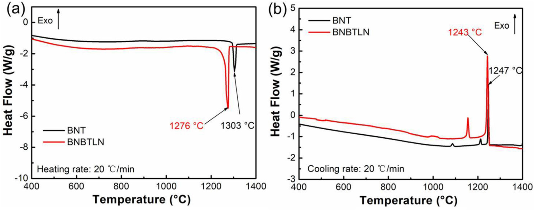
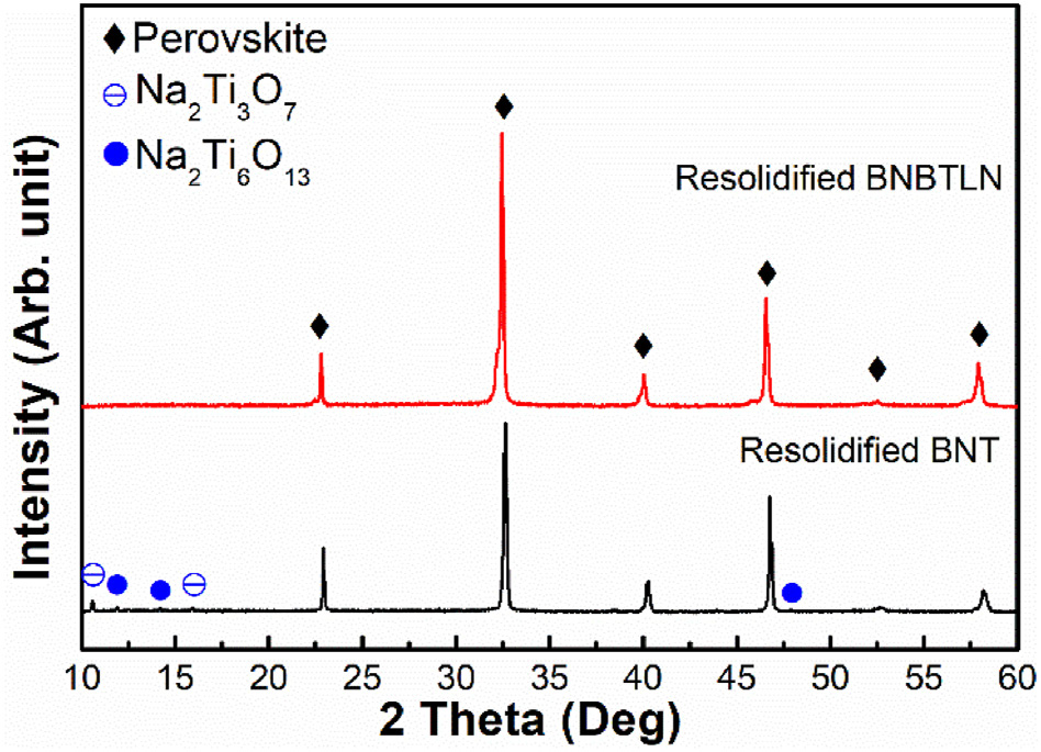
Since the melting-recrystallization process was involved in the thermal spray process, the melting and recrystallization behaviors of BNBTLN ceramic powder were studied in comparison with BNT by the DSC test shown in Figure 1 BNT was reported to be a congruent melting composition [32,33]. The DSC curve of BNT in Figure 1a exhibited a single sharp melting peak at 1,303°C, and BNBTLN showed a similar melting behavior with a lower melting point at 1,276°C. The lithium niobate dopant in the BNT-BT system was believed to contribute to the lowered melting point [34,35]. In the cooling DSC curve of BNT, there was one major sharp peak at 1,247°C, followed by two small peaks on the lower temperature side. BNBTLN had one major sharp peak at 1,243°C, followed by one small peak on the lower temperature side. XRD patterns of the resolidified BNT and BNBTLN were shown in Figure 2. Both exhibit major perovskite phase, which could correspond to the major peaks in cooling DSC curves. In addition, minor Bi-deficient Na2Ti3O7 and Na2Ti6O13 secondary phases were detected in the resolidified BNT due to the more serious volatile loss of Bi than that of Na.
3.2 Structure and morphology of BNBTLN coatings
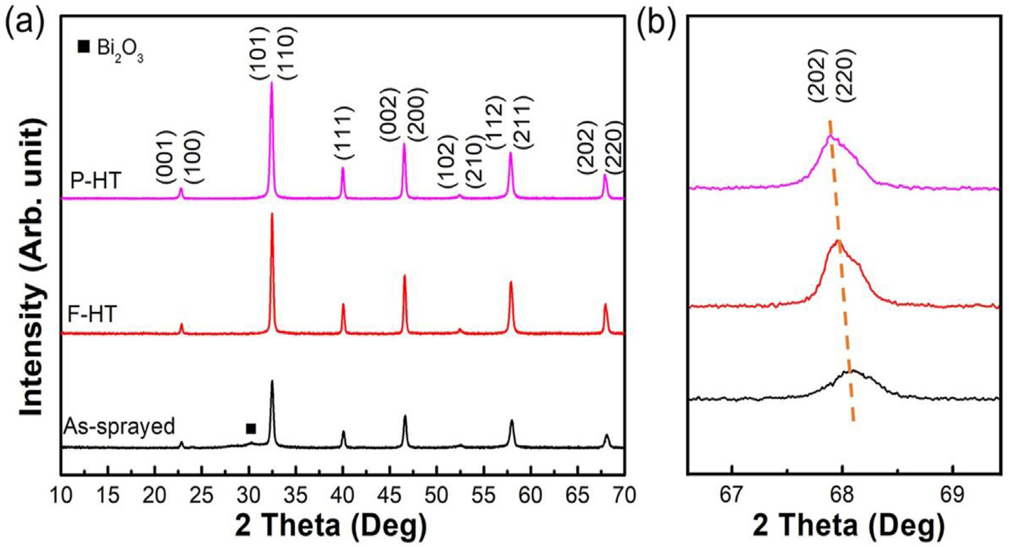
The XRD patterns of thermal sprayed BNBTLN coatings are presented in Figure 3. The as-sprayed coating exhibited a tiny hump of the amorphous phase. After heat treatment, all the BNBTLN coatings showed a single phase of perovskite structure with significantly increased intensity of diffraction peaks compared to the as-sprayed coating, indicating the heat treatment by both furnaces and plasma torch effectively enhanced the crystallinity. Additionally, the diffraction peaks shift to smaller angles after F-HT and P-HT (shown in Figure 3b), indicating a larger lattice space. This phenomenon could potentially be attributed to the presence of tensile stress [36].
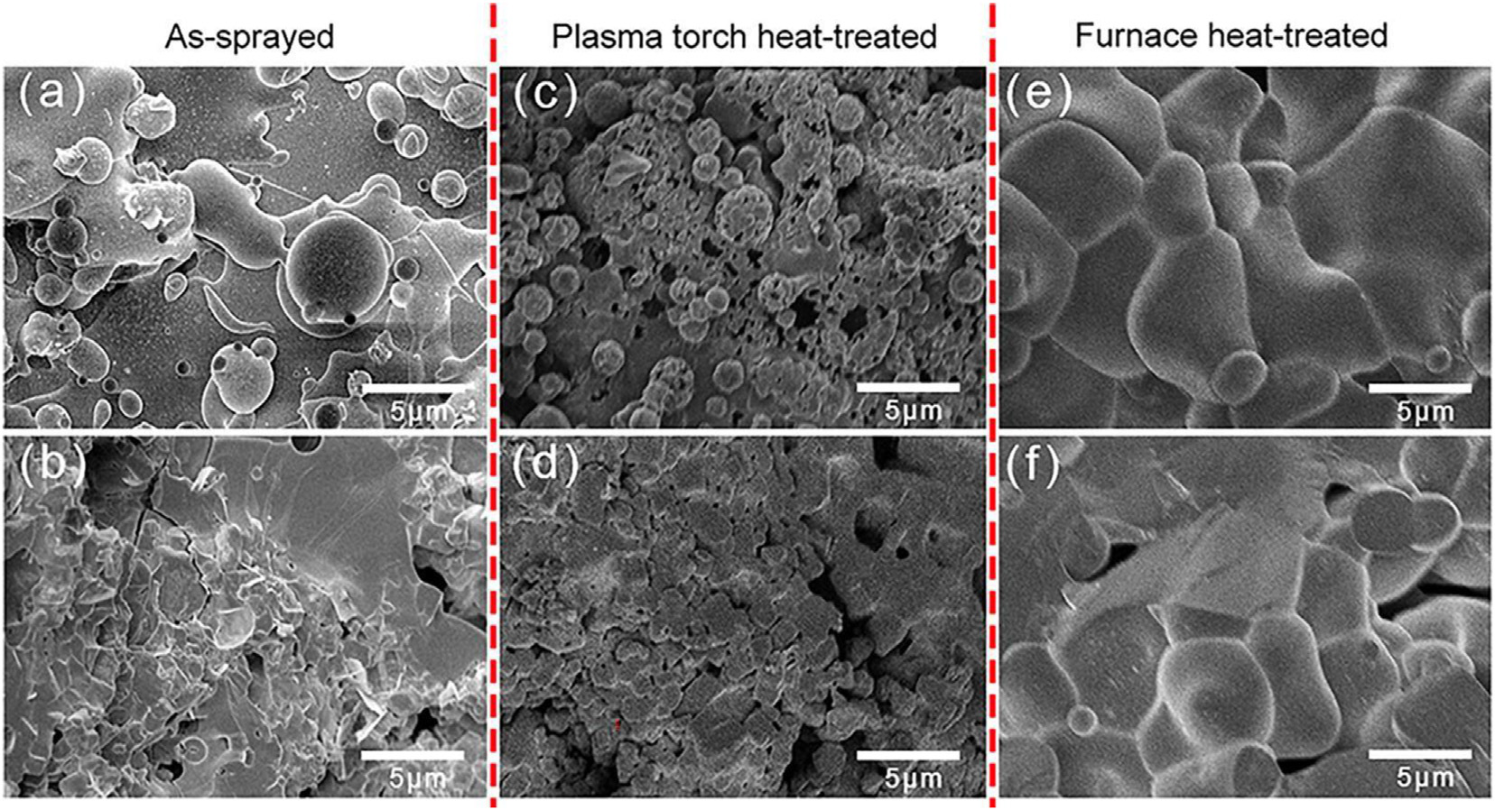
Figure 4 presents the FESEM images of the surface and cross-section for BNBTLN thermal sprayed coating before and after the heat treatments. As shown in Figure 4a, the surface of the as-sprayed coating consists of a mixture of spherical and irregularly-shaped particles, which is a typical morphology resulting from rapid cooling and solidification after melting. The morphology indicate that the crystallization was not fully completed from the cool melt in the as-deposited coating [37]. In addition, as presented in Figure 4b, it can be seen from the cross-section of the coating that the grains are uneven with irregular grain boundaries. After heat treatment, a significant increase in grain size and crystallinity was observed. As shown in Figure 4c, a large number of crystallized grains on the surface of the coating can be observed after P-HT. As presented in Figure 4d, the cross-section morphology of the coating after P-HT treatment is relatively dense with a more regular shape than the as-sprayed coating. Furthermore, the incompletely crystallized particles have also been recrystallized during the heat treatment, giving rise to the clear grain boundaries. Likewise, the morphology of the surface and cross-section recorded after F-HT is presented in Figure 4e and 4f, respectively. Due to the longer time and a more uniform heating process, the F-HT produced denser morphology and higher crystallinity than P-HT.
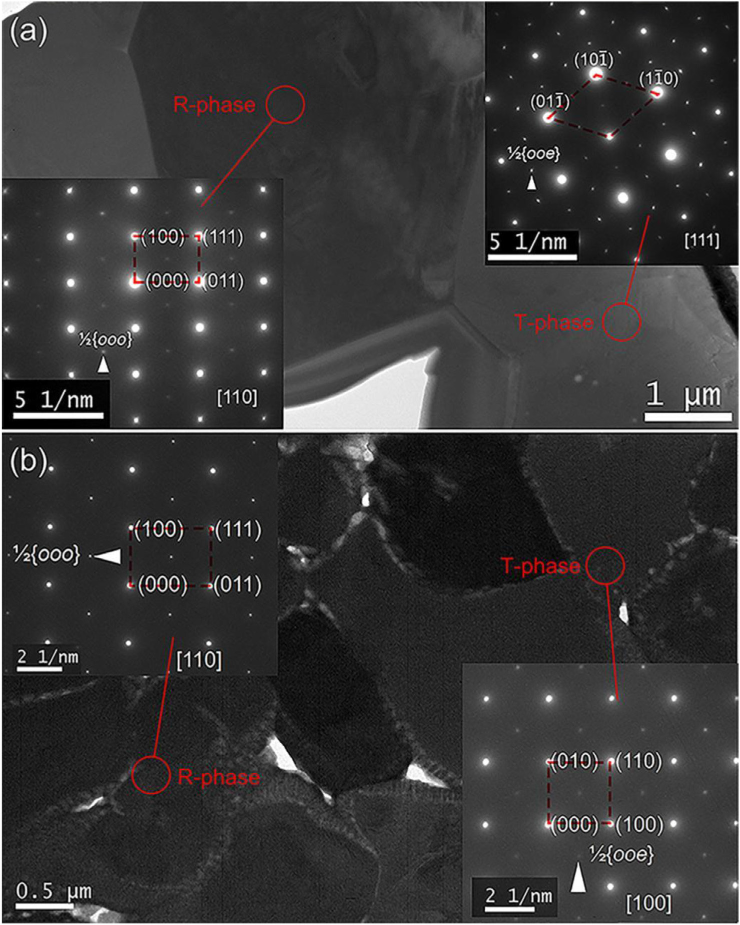
The bright field TEM image in Figure 5a revealed more details of the BNBTLN coating after F-HT, with the selected area electron diffraction (SAED) patterns obtained along [111] and [110] zone axes showing the presence of 1/2{ooe} and 1/2{ooo} superlattice reflections, respectively. The in-phase (a0a0c+) tilting of oxygen octahedrons in the P4bm phase contributed to the presence of 1/2{ooe} superlattice reflections along [110] direction, indicating the perovskite phase had a tetragonal characteristic. The 1/2{ooo} superlattice spots along [110] indicated the antiphase (a–a–a–) oxygen octahedral tilting in the R3c phase, which was not visible in P4mm and P4bm phases [38, 39, 40, 41]. These superlattice diffractions provided solid evidence for the coexistence of R-T phase in the same grain in thermal sprayed BNBTLN coatings after F-HT. The MPB of R-T phase was expected to enhance the subsequent electrical properties, similar to the effect observed in bulk ceramic.
Similarly, Figure 5b presents TEM images of BNBTLN coatings after P-HT, with SAED patterns obtained along [100] and [110] zone axes. The 1/2{ooe} superlattice diffractions in the SAED of [100] direction, in addition to the fundamental perovskite reflections, indicated a tetragonal characteristic of the perovskite phase. The alignment of the 1/2{ooo} superlattice spots along [110], revealed the presence of an R3c rhombohedral perovskite phase in the thermal sprayed BNBTLN coating. This indicated that the MPB of R-T phase also existed in the P-HT coating.
In addition, the measured reciprocal space vector |G(111)| and |G(110)| in R-phase and T-phase for F-HT were 4.43 nm-1 and 3.70 nm-1, respectively. The corresponding real space distances, calculated from the inverse of |GF(111)| and |GF(110)|, were dF(111) = 2.26 Å and dF(1 0) = 2.70 Å, respectively. For P-HT, the measured |GP(111)| and |GP(110)| in R-phase and T-phase were 4.39 nm-1 and 3.61 nm-1, respectively. The corresponding real space distances were dP(111) = 2.28 Å and dP(110) = 2.77 Å, respectively. The distances of dF(111) and dF(110) were greater than dP(111) and dP(110), respectively, indicating that the lattice parameter of P-HT is larger than that of F-HT, which is consistent with the XRD diffraction peaks being shifted.
3.3 Dielectric, ferroelectric, and piezoelectric properties
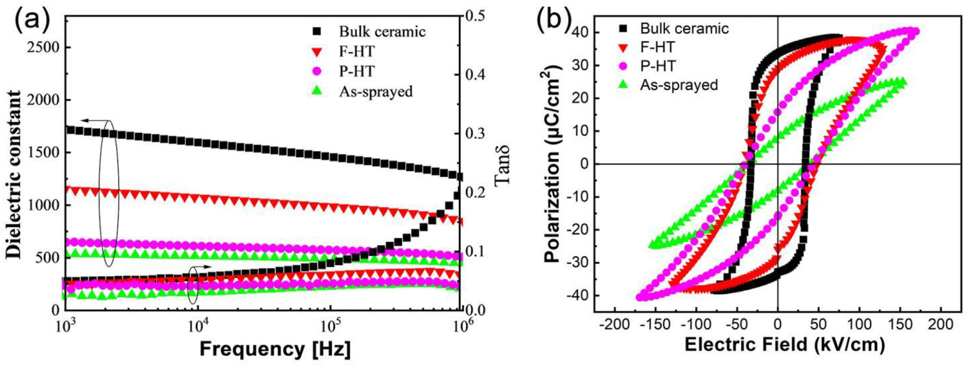
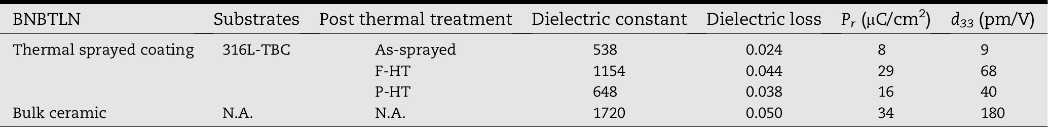
The dielectric and ferroelectric properties of the heat-treated coatings were subsequently investigated and compared to those of bulk ceramics. Figure 6a shows heat treatment significantly enhances the dielectric properties of thermal sprayed BNBTLN coatings, which is mainly attributed to the improved crystallinity and densification of the coating. As presented in Table 1, at the measurement frequency of 10 kHz and room temperature, the dielectric constants of F-HT and P-HT samples are 1,154 and 648, respectively, with the former being significantly higher than the latter, yet still lower than 1,720 of bulk ceramics.
The dielectric loss of the coating after heat treatment is lower compared with the as-sprayed coating. Compared with the as-sprayed coatings, the P-E loop of the BNBTLN ceramic coating after heat treatment shows the remnant polarization increased significantly with improved saturation. While both the F-HT and P-HT processes improved electrical properties of the as-sprayed coating, the F-HT processed coating still exhibited the best dielectric and ferroelectric properties.
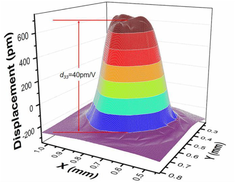
After poling at room temperature under 55 kV/cm for 10 minutes, the effective piezoelectric coefficient d33 of the BNBTLN coatings was measured by the LSV method [42]. Figure 7 presents the displacement magnitude of BNBTLN coating after P-HT measured under the excitation of a sine wave of 10 V in amplitude at 1 kHz. Since the top (covered with the top electrode) of the 3D plotted data was uneven, the average value over the top area instead of the highest point was used to calculate the effective d33. The thermal sprayed BNBTLN coatings after P-HT had the effective piezoelectric coefficient d33 of 40 p.m./V. In addition, Table 1 also compares the d33 of the thermal sprayed coatings and the bulk ceramic of BNBTLN. The as-sprayed coating shows effective piezoelectric coefficient d33 of 9 p.m./V, which reached 68 p.m./V after F-HT. The d33 of BNBTLN bulk ceramic is 180 p.m./V, which is relatively high compared with the BNBTLN thermal sprayed coatings.
3.4 Comparative analysis of F-HT and P-HT processes
Figure 8 illustrates the process of F-HT and P-HT and the associated grain growth details. The as-sprayed coating exhibits the presence of amorphous regions and a significant number of porosities along with a relatively small grain size. In the conventional F-HT, the workpiece with the thermal sprayed coating is heated to a high temperature through slow heating in the furnace, with the temperature in the furnace relatively stable and the heat flow emanating from all directions.
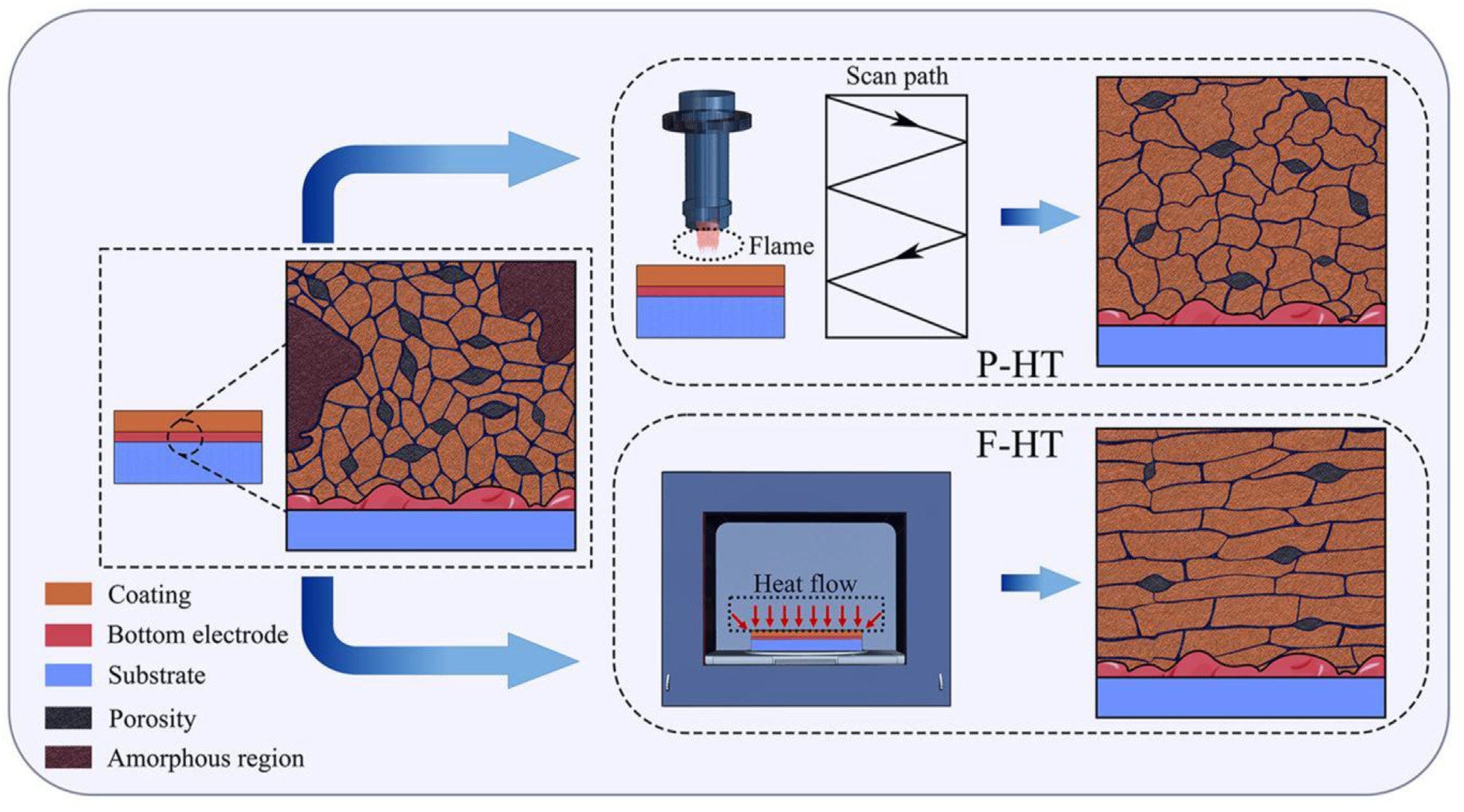
Prolonged heat flux leads to the gradual disappearance of the amorphous regions involved in the coatings, with the grain boundaries becoming increasingly distinct and the grain size becoming uniform, yet a small number of interlayer voids remained.
The P-HT uses a plasma torch as a heat source, which sprays a plasma flame of extremely high temperature directly onto the surface of the coating and scans the flame on the surface in a back-and-forth manner. At the high temperature of the plasma flame, the grains rapidly crystallize and grow. However, the heat from the plasma torch is directional with sharp interfaces and steep thermal gradients. The inhomogeneous heat source leads to irregular grain size and shape, which hinders the formation of regular layered grain morphology. The temperature change during P-HT of the sprayed coating along the scanning path was much faster, which may not favor formation of uniform nucleation and adequate grain growth. Although the density of the coating after P-HT is not as good as that of the coating after F-HT, the heat treatment time is greatly reduced, and the oxidation damage to the metal substrate is avoided, meanwhile, it is scalable for forming thermal sprayed piezoelectric ceramic coating in large engineering structures. These features are highly demanded for many practical applications, such as in ultrasonic structural health monitoring [43].
4 Conclusions
BNBTLN piezoelectric ceramic coating was deposited by thermal spray on stainless steel substrates with thermal barrier coating (TBC). Both the furnace heat treatment (F-HT) and plasma torch heat treatment (P-HT) significantly improved the crystallinity with R-T phase coexistence and enhanced the ferroelectric and piezoelectric properties of the BNBTLN coatings. F-HT provided gradual and uniform heating beneficial to more homogeneous grain morphology, higher density, and better electrical properties. P-HT offered a scalable, fast, and on-site processing method.
After P-HT, an effective piezoelectric coefficient d33 of 40 p.m./V was obtained. These results reveal that high-quality piezoelectric coatings can be achieved by the P-HT method, which is promising for scaling up the fabrication of piezoelectric ceramic coatings using for SHM.
• © The Author(s) 2023. Published by Elsevier B.V. This article (https://www.sciencedirect.com/science/article/pii/S2238785423025243) is an open access article distributed under the terms and conditions of the Creative Commons Attribution (CC BY) license (https://creativecommons.org/licenses/by/4.0/). The article has been edited to conform to the style of Thermal Processing magazine.
References
- K. Shibata, R. Wang, T. Tou, J. Koruza. Applications of lead-free piezoelectric materials. MRS Bull, 43 (2018), pp. 612-616, 10.1557/mrs.2018.180.
- J. Koruza, A.J. Bell, T. Frömling, K.G. Webber, K. Wang, J. Rödel. Requirements for the transfer of lead-free piezoceramics into application. J Materiomics, 4 (2018), pp. 13-26, 10.1016/j.jmat.2018.02.001.
- J. Rödel, J.-F. Li. Lead-free piezoceramics: status and perspectives. MRS Bull, 43 (2018), pp. 576-580, 10.1557/mrs.2018.181.
- G.-J. Lee, B.-H. Kim, S.-A. Yang, J.-J. Park, S.-D. Bu, M.-K. Lee. Piezoelectric and ferroelectric properties of (Bi,Na)TiO3-(Bi,Li)TiO3-(Bi,K)TiO3 ceramics for accelerometer application. J Am Ceram Soc, 100 (2017), pp. 678-685, 10.1111/jace.14614
- J.-J. Choi, B.-D. Hahn, J. Ryu, W.-H. Yoon, B.-K. Lee, D.-S. Park. Preparation and characterization of piezoelectric ceramic–polymer composite thick films by aerosol deposition for sensor application. Sens Actuators A, 153 (2009), pp. 89-95, 10.1016/j.sna.2009.04.025.
- J. Akedo Room temperature impact consolidation (RTIC) of fine ceramic powder by aerosol deposition method and applications to microdevices. J Therm Spray Technol, 17 (2008), pp. 181-198, 10.1007/s11666-008-9163-7.
- A. Safari, R.K. Panda, V.F. Janas. Ferroelectricity: materials, characteristics & applications. Key Eng Mater, 122 (1996), pp. 35-70, 10.4028/www.scientific.net/KEM.122-124.35.
- Q. Zhao, L. Yang, Y. Ma, H. Huang, H. He, H. Ji, et al. Highly sensitive, reliable and flexible pressure sensor based on piezoelectric PVDF hybrid film using MXene nanosheet reinforcement. J Alloys Compd, 886 (2021), Article 161069, 10.1016/j.jallcom.2021.161069.
- H. Zhang, S. Jiang. Effect of repeated composite sol infiltrations on the dielectric and piezoelectric properties of a Bi0.5(Na0.82K0.18)0.5TiO3 lead free thick film. J Eur Ceram Soc, 29 (2009), pp. 717-723, 10.1016/j.jeurceramsoc.2008.07.049.
- J. Pavlič, B. Malič, T. Rojac. Small reduction of the piezoelectric d33 response in potassium sodium niobate thick films. J Am Ceram Soc, 97 (2014), pp. 1497-1503, 10.1111/jace.12797.
- R. Maas, M. Koch, N.R. Harris, N.M. White, A.G.R. Evans. Thick-film printing of PZT onto silicon Mater Lett, 31 (1997), pp. 109-112, 10.1016/S0167-577X(96)00249-2.
- S. Trolier-McKinstry, P. Muralt. Thin film piezoelectrics for MEMS. J Electroceram, 12 (2004), pp. 7-17, 10.1023/B:JECR.0000033998.72845.51.
- K. Tsuchiya, T. Kitagawa, E. Nakamachi. Development of RF magnetron sputtering method to fabricate PZT thin film actuator Precis Eng, 27 (2003), pp. 258-264, 10.1016/S0141-6359(03)00006-0.
- P.C. Goh, K. Yao, Z. Chen. Lead-free piezoelectric (K0.5Na0.5)NbO3 thin films derived from chemical solution modified with stabilizing agents. Appl Phys Lett, 97 (2010), Article 102901, 10.1063/1.3488808.
- W. Liu, W. Zhu. Preparation and orientation control of Pb1.1(Zr0.3Ti0.7)O3 thin films by a modified sol–gel process. Mater Lett, 46 (2000), pp. 239-243, 10.1016/S0167-577X(00)00178-6.
- L. Wang, K. Yao, W. Ren. Piezoelectric K0.5Na0.5NbO3 thick films derived from polyvinylpyrrolidone-modified chemical solution deposition. Appl Phys Lett, 93 (2008), Article 092903, 10.1063/1.2978160.
- G. Han, J. Ryu, C.-W. Ahn, W.-H. Yoon, J.-J. Choi, B.-D. Hahn, et al. High piezoelectric properties of KNN-based thick films with abnormal grain growth. J Am Ceram Soc, 95 (2012), pp. 1489-1492, 10.1111/j.1551-2916.2012.05139.x.
- B. Malric, S. Dallaire, K. El-Assal. Crystal structure of plasma-sprayed PZT thick films. Mater Lett, 5 (1987), pp. 246-249, 10.1016/0167-577X(87)90103-0.
- S. Sherrit, C.R. Savin, H.D. Wiederick, B.K. Mukherjee, S.E. Prasad. Plasma-Sprayed lead zirconate titanate-glass composites. J Am Ceram Soc, 77 (1994), p. 1973, 10.1111/j.1151-2916.1994.tb07082.x–1975.
- P. Ctibor, H. Seiner, J. Sedlacek, Z. Pala, P. Vanek. Phase stabilization in plasma sprayed BaTiO3. Ceram Int, 39 (2013), pp. 5039-5048, 10.1016/j.ceramint.2012.11.102.
- K. Yao, S. Chen, S.C. Lai, Y.M. Yousry. Enabling distributed intelligence with ferroelectric multifunctionalities. Adv Sci, 9 (2022), Article 2103842, 10.1002/advs.202103842.
- R. Thielsch, W. Hassler, W. Bruckner. Electrical properties and mechanical stress of thick plasma-sprayed Pb(Zr0.58Ti0.42)O3 coatings. Phys Status Solidi A, 156 (1996), pp. 199-207, 10.1002/pssa.2211560124.
- G. Li, L. Gu, H. Wang, Z. Xing, L. Zhu. Microstructures and dielectric properties of PZT coatings prepared by supersonic plasma spraying. J Therm Spray Technol, 23 (2013), pp. 525-529, 10.1007/s11666-013-0040-7.
- Z. Liu, Z. Xing, H. Wang, X. Cui, G. Jin, S. Chen. Fabrication and post heat treatment of 0.5Pb(Mg1/3Nb2/3)O3 -0.5Pb(Zr 0.48Ti0.52)O3 coatings by supersonic plasma spray. J Eur Ceram Soc, 37 (2017), pp. 3511-3519, 10.1016/j.jeurceramsoc.2017.04.043.
- P. Ctibor, Z. Pala, H. Boldyryeva, J. Sedláček, V. Kmetík. Microstructure and properties of plasma sprayed lead zirconate titanate (PZT) ceramics Coatings, 2 (2012), pp. 64-75, 10.3390/coatings2020064.
- K. Guo, S. Chen, C.K.I. Tan, M. Sharifzadeh Mirshekarloo, K. Yao, F.E.H. Tay. Bismuth sodium titanate lead-free piezoelectric coatings by thermal spray process. J Am Ceram Soc, 100 (2017), pp. 3385-3392, 10.1111/jace.14882.
- K. Guo, M. Sharifzadeh Mirshekarloo, K. Yao, F.E.H. Tay. Structural evolution of thermal sprayed bismuth sodium titanate piezoelectric ceramic coatings. J Am Ceram Soc, 102 (2019), pp. 2370-2376, 10.1111/jace.16135.
- M. Gabilondo, I. Fraile, N. Burgos, M. Azcona, F. Castro. Microstructural comparison between precursor-based and particle-based PZT ceramic coatings. Ceram Int, 45 (2019), pp. 23149-23156, 10.1016/j.ceramint.2019.08.009.
- P. Ctibor, J. Sedlacek, Z. Pala. Structure and properties of plasma sprayed BaTiO3 coatings after thermal posttreatment. Ceram Int, 41 (2015), pp. 7453-7460, 10.1016/j.ceramint.2015.02.065.
- S. Chen, C.K.I. Tan, K. Yao. Potassium–sodium niobate-based lead-free piezoelectric ceramic coatings by thermal spray process. J Am Ceram Soc, 99 (2016), pp. 3293-3299, 10.1111/jace.14342.
- L. Zhou, X. Li, D. He, W. Guo, Y. Huang, G. He, et al. Study on properties of potassium sodium niobate coating prepared by high efficiency supersonic plasma spraying Actuators, 11 (2022), p. 28, 10.3390/act11020028.
- M. Woll, M. Burianek, D. Klimm, S. Gorfman, M. Mühlberg. Characterization of (Bi0.5Na0.5)1−xBaxTiO3 grown by the TSSG method. J Cryst Growth, 401 (2014), pp. 351-354, 10.1016/j.jcrysgro.2013.11.102.
- K. Uchida, T. Kikuchi. Subsolidus phase equilibria in the system Na2O-Bi2O3-TiO2 at 1000°C. J Am Ceram Soc, 61 (1978), pp. 5-8, 10.1111/j.1151-2916.1978.tb09217.x.
- Y. Zhang, G. Liang, S. Tang, B. Peng, Q. Zhang, L. Liu, et al. Phase-transition induced optimization of electrostrain, electrocaloric refrigeration and energy storage of LiNbO3 doped BNT-BT ceramics. Ceram Int, 46 (2020), pp. 1341-1351, 10.1016/j.ceramint.2019.09.097.
- Q. Feng, K. Huang, N. Luo, C. Yuan, C. Zhou, Y. Wei, et al. Formation mechanism, dielectric properties, and energy-storage density in LiNbO3-doped Na0.47Bi0.47Ba0.06TiO3 ceramics. J Mater Sci Mater Electron, 31 (2020), pp. 13368-13375, 10.1007/s10854-020-03891-w.
- M. Dailey, Y. Li, A.D. Printz. Residual film stresses in perovskite solar cells: origins, effects, and mitigation strategies ACS Omega, 6 (2021), pp. 30214-30223, 10.1021/acsomega.1c04814.
- S. Saber-Samandari, C.C. Berndt. IFTHSE Global 21: heat treatment and surface engineering in the twenty-first century Part 10–Thermal spray coatings: a technology review. Int Heat Treat Surf Eng, 4 (2010), pp. 7-13, 10.1179/174951410X12572442577381.
- K. Yan, S. Ren, M. Fang, X. Ren. Crucial role of octahedral untilting R3m/P4mm morphotropic phase boundary in highly piezoelectric perovskite oxide.Acta Mater, 134 (2017), pp. 195-202, 10.1016/j.actamat.2017.05.066.
- G.O. Jones, P.A. Thomas. Investigation of the structure and phase transitions in the novel A-site substituted distorted perovskite compound Na0.5Bi0.5TiO3. J Am Ceram Soc, 58 (2002), pp. 168-178, 10.1107/S0108768101020845.
- D.I. Woodward, I.M. Reaney. Electron diffraction of tilted perovskites. J Am Ceram Soc, 61 (2005), pp. 387-399, 10.1107/S0108768105015521.
- C.W. Tai, Y. Lereah. Nanoscale oxygen octahedral tilting in 0.90(Bi1/2Na1/2)TiO3–0.05(Bi1/2K1/2)Ti3–0.05BaTiO3 lead-free perovskite piezoelectric ceramics. Appl Phys Lett, 95 (2009), Article 062901, 10.1063/1.3193544.
- K. Yao, F.E.H. Tay. Measurement of longitudinal piezoelectric coefficient of thin films by a laser-scanning vibrometer IEEE Trans Ultrason Ferr, 50 (2003), pp. 113-116, 10.1109/TUFFC.2003.1182115.
- S. Guo, L. Zhang, S. Chen, C.K.I. Tan, K. Yao. Ultrasonic transducers from thermal sprayed lead-free piezoelectric ceramic coatings for in-situ structural monitoring for pipelines. Smart Mater Struct, 28 (2019), Article 075031, 10.1088/1361-665X/ab1e88.


 general practice for CQI-9 and AMS2750E")


