


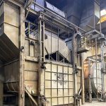
Steel components by far represent the majority of thermally processed workpieces for which electromagnetic induction is used as a source of heat generation. At the same time, induction heating has also been successfully applied for heat treating of a variety of iron castings offering numerous attractive properties, microstructures, and cost advantages for different commercial applications (Figure 1). This includes hardening of camshafts, crankshafts, sprockets, crane wheels, gear housing, cylinder liners, rollers, rocker arms, flywheels, connecting rods, and many others.

Induction hardening (IH) of cast irons has many similarities with hardening of steels; at the same time, there are specific features that should be taken into consideration [1]. Some of those features will be reviewed in this article.
Family of Cast Irons
The term cast iron does not represent one particular material but a large family of metallic alloys featuring the high carbon content region of the phase transformation diagram (2 percent and higher). Generally speaking, the family of cast irons can be categorized into six groups: white, gray, malleable, ductile (also called nodular, spheroidal, or SG), compacted graphite (CGI), and special high-alloy cast irons [2-5].
Upon the completion of solidification of cast irons, either graphite particles of different morphologies (for a majority of commercial cast irons) or cementite Fe3C (e.g., white cast iron) are formed.
Besides carbon, commercial cast irons consist of 0.6 percent to 4 percent Si (with 2 percent to 3.5 percent Si being more typical), making these the two principal alloying elements. Silicon promotes a graphite formation. Therefore, because of the considerable amount of, it is more appropriate to consider commercial cast irons not as binary alloys but at least ternary Fe–C–Si alloys. In contrast to the Fe–C diagram, the eutectic reactions on the Fe–C–Si diagram occur at higher temperatures and over a range of temperatures that increases with an increase of both the carbon and silicon content.
In order to provide certain properties for a particular type of cast iron, various alloying elements (including Mn, P, Ni, Mg, Ce, etc.) may be added [2-5]. Unlike steels, different types of cast irons may have similar chemical composition but substantially different response to IH.
The graphite particles appear in cast irons in different forms ranging from flakes and clumps to spheroids. Gray, ductile (nodular), and, to a lesser extent, the malleable and compacted graphite irons are four groups of cast irons that more frequently undergo induction hardening.
Gray cast irons, being relatively inexpensive metallic materials with remarkable castability and machinability, excellent wear resistance, and resistance to galling and seizure/spalling (graphite flakes provide solid lubrication) are very attractive for a variety of applications.

Induction Hardening of Gray Cast Irons
The properties of gray irons and their ability to be induction hardened greatly depend on the type of the matrix structure (e.g., ferritic, ferritic–pearlitic, or pearlitic). Cast irons with a ferritic matrix or predominantly ferritic matrix are commonly considered unsuitable for rapid IH due to the lack of ability to obtain the typically needed hardness levels. Fully pearlitic or predominately pearlitic (e.g., a mixture containing 90 percent pearlite and 10 percent ferrite) gray irons have better response to IH compared to a matrix with an increased amount of ferrite.
Fine graphite flakes that are uniformly distributed and randomly oriented (type “A”) are the most preferable type of flakes for IH [1]. Being stress-risers, graphite flakes may act as crack initiation sites presenting some brittleness and introducing certain challenges because of the tendency toward cracking upon rapid heating as well as during intense quenching in particular when dealing with complex geometries. Preheating and the use of moderate intensity quenchants may be applied to reduce thermal stresses.
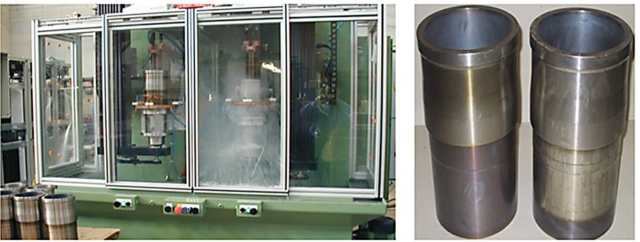
At the same time, there are cases when gray irons have been successfully surface-hardened using a short heat time (less than 3 seconds) and water spray quenched. As an example, Figure 3 shows a unitized machine for IH of gray iron cylinder liners for commercial vehicle engines. It combines two independently operated heat stations for hardening and tempering. High-speed, servo-driven scanning assemblies and an optimized process recipe allow very short heating times and production rates as high as 50 liners per hour. Hardness case depth is 0.75 mm (0.03 inches). The entire inner surface of the liner is hardened except for a 6-mm (1/4-inches) band at each end with minimum distortion.
Induction Hardening of Ductile (Nodular) Cast Irons
In contrast to gray irons, ductile irons have graphite particles in the form of isolated nodules (Figure 2, right). Graphite nodules serve as “crack-arresters,” providing ductile irons with important advantages over other cast irons, including but not limited to ductility, relatively high tensile and bending strength, moderate elongation, and better toughness with comparable machinability. Though there is an optimal combination of the size, number, and distribution of the nodules for certain applications, usually graphite nodules of smaller diameters that are uniformly dispersed within the matrix are preferred.
Ductile irons represent a group of materials offering versatile properties. The group can be divided into five subgroups based on the structure of the matrix: ferritic, pearlitic-ferritic, pearlitic, martensitic, and austempered ductile irons. Similar to gray irons, the matrix structure of ductile irons is also controlled by the cooling intensity during casting, as well as by alloying (e.g. Ce, Mg, etc.) and heat treatment.
IH is usually applied to martensitic and pearlitic (or predominately pearlitic) ductile irons and, to lesser extent, pearlitic-ferritic ductile irons having a considerable amount of ferrite. Ductile irons consisting of a ferritic matrix structure are commonly considered non-hardenable by induction because of the inability to obtain the hardness levels typically needed for most applications.
However, as always in life, there are some exceptions. It has been reported [6] that upon rapid heating, short austenitization, and intense quenching, the fatigue strength of ferritic ductile irons has been noticeably improved compared to untreated castings. It was suggested that several factors contributed to observed improvements. One such factor is related to the formation of so-called ringed martensite formed around the graphite nodules, thanks to the short-distance diffusion of the carbon from the graphite nodules. The presence of ringed martensite leads to a localized hardness increase and is associated with an increase of strength. Another possible factor may be associated with favorable distribution and magnitude of compressive residual stresses. As a result of the bending fatigue test of an untreated specimen, it was noted that the crack initiation site was located around the graphite spheres, and it propagated through the ferritic matrix and graphite nodules [6]. In the case of the induction heat-treated specimen, the graphite area was somewhat smaller, and the crack was initiated within the ferrite phase and propagated, avoiding graphite nodules surrounded by a halo of the ringed martensite.
Nevertheless, IH of ferritic ductile irons used in this case study is more the exception than the rule and for the majority of IH applications, a ferritic or predominantly ferritic matrix of cast irons is highly undesirable because of the inability to achieve the consistency and hardness levels typically needed in industry.
Being inherently strong, ductile irons can handle much greater stresses than gray irons. Though, graphite nodules of ductile irons serve as “crack-arresters,” their existence does not guarantee that ductile iron castings will not crack during rapid heating or severe quenching. Caution should be applied when choosing process parameters for surface hardening of iron castings of complex geometries.
Electro-Thermal Properties of Cast Irons
Unlike alternative processes, the performance of induction systems first and foremost is affected by the electromagnetic properties of the heated materials, including electrical resistivity r and relative magnetic permeability µr.
The chemical composition and volume fraction of graphite, its morphology, and the matrix structure of cast irons affect not only mechanical properties but also electromagnetic and thermal properties. For example, gray irons with large graphite flakes are known to have a higher thermal conductivity k and a lower electrical resistivity p. Ductile irons with a ferritic matrix have a higher k compared to pearlitic or Q&T grades.
The thermal conductivity of cast irons decreases with an increase in Mn and P content. It has been reported [2] that if Cu content is less than 2 percent, it lowers k. Cu additions greater than 2 percent have no appreciable effect on k. An increase in Si reduces k of most cast irons. For a given grade of cast iron, k usually decreases with temperature.
Reference [2] provides comprehensive data regarding the electromagnetic properties of cast irons and can be summarized using the following selected points:
- p gradually increases with the temperature rise and behaves in a complex manner, being a function of chemical composition, morphology of the graphite, and microstructure of matrix.
- Cast irons with nodular or close-to-nodular morphology of graphite (e.g., ductile or malleable cast irons) exhibit lower p compared to gray irons.
- Gray irons with courser graphite flakes exhibit higher p compared to finer flakes.
- Figure 4, left, illustrates the effect of Si on p of pearlitic and ferritic ductile cast irons at room temperature. Figure 4, right, shows the influence of Al, Mn, and Ni on p of gray irons at room temperature [2,7].
- A pearlitic matrix results in increased p compared to cast irons with a ferritic matrix. Pearlitic cast irons having fine spacing between the lamellae have greater p compared to coarser pearlites. Ductile iron with a ferritic matrix has the lowest p.

Cast irons with a ferritic matrix have higher magnetic properties compared to pearlitic irons. It appears that ductile and malleable irons exhibit greater magnetic induction B and higher µr compared to the respective properties of gray irons. Cast irons exhibit noticeably lower residual magnetism, magnetic saturation, and µr compared to carbon steels.
Good Practices in Induction Hardening of Cast Irons
Process Related Subtleties
Among other factors, the ability of cast irons to exhibit certain as-quench hardness and strength depends upon the amount of carbon contained in the austenite, which is greatly affected by the matrix. The proper hardening parameters include, but are not limited to, an appropriate temperature and time at the austenite phase, which, besides other factors, are functions of the cast iron grade, its matrix, heat intensity, and quenching specifics.
In steels, the carbon content is fixed by chemistry and, upon austenitization, cannot exceed this fixed value (rare attempts to use a carbon-enriched environment are excluded from consideration). In contrast, in cast irons, there is a “reserve” of carbon in the primary (eutectic) graphite particles. The presence of those graphite particles and the ability of carbon to diffuse into the matrix at temperatures of austenite phase can potentially cause the process variability, because it may produce a localized deviation/increase in an amount of carbon dissolved in the austenitic matrix respectively affecting the obtained hardness and its uniformity upon quenching [1].
Higher temperatures of the austenite phase and longer times at those temperatures are associated with a greater amount of carbon being dissolved within the matrix. Since some of the graphite can go into solution in proximity to nodules or flakes, it can locally increase the carbon level in the austenite, shifting CCT curves, affecting martensitic formation and Ms temperatures, as well as amount of retained austenite (RA). This tendency is an important metallurgical factor representing one of the major differences between hardening cast irons versus steels and potentially resulting in a variable amount of carbon in as-quenched structure. This is one of the reasons why the requirements for process control and monitoring when hardening cast irons are usually more stringent compared to hardening steels.
An attempt to compensate for the lack of carbon content in the ferritic matrix trying to purposely diffuse a greater amount of carbon into austenite by applying excessively high temperatures and dissolving the primary graphite particles cannot be considered a good universal practice because it is associated with not only the necessity of reaching unduly high austenizing temperatures but also the need to hold the cast irons at those temperatures for an extended period. This discourages one of the main advantages of induction, the short process time and results in grain coarsening, excessive amount of RA, irregular hardness patterns, and crack susceptibility.
On the other hand, insufficient austenitization produces heterogeneous structures forming a mixture of martensitic and non-martensitic products (“ghost” products) and undesirable engineering properties. The industry has accumulated several recommendations to estimate the appropriate hardening temperatures. For a rough estimation of the minimum required austenitizing temperature of unalloyed cast irons heated at moderate heat intensity, the following expressions are often applied:
Austenizing temperature, °C = 800 + 28(%Si) – 25(%Mn)
Austenizing temperature, °F = 1,472 + 50(%Si) – 45(%Mn).
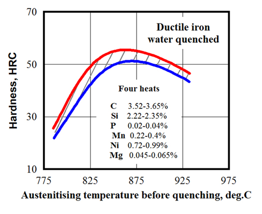
Besides the minimum austenitic temperature, there is a maximum recommended temperature that should not be exceeded. The temperature range of 860°C (1,580°F) to 930°C (1,706°F) is typical for IH of gray and ductile iron castings. As an example, Figure 5 shows the influence of austenitizing temperature on the hardness of water-quenched ductile iron [8].
Keep in mind that, as a result of the non-equilibrium nature of rapid induction heating, all critical temperatures are shifted toward the higher temperatures. Cast iron eutectic melts at temperatures of approximately 150°C to 250°C lower than the majority of plain carbon steels. For example, in the case of moderate heat intensity, the unalloyed cast iron eutectic starts to melt at temperatures of about 1,130°C (2,066°F). Therefore, if something goes wrong, there is a distinct possibility for overheating owing to the relatively low liquidus and solidus temperatures of cast irons. The situation becomes more complicated, as certain alloying elements (such as copper or tin, which may be added to some cast irons) have low melting temperatures.
In contrast to steels, there is very limited information in the literature with respect to the continues heating transformation (CHT) diagrams suitable for IH of cast irons, forcing heat treaters to rely solely on experiments and laboratory developments to determine the most appropriate temperatures for rapid IH.
When heating cast irons susceptible to cracking, it is sometimes useful to preheat the castings allowing the reduction of thermal shocks or to apply modest heat intensity in particular during the initial stage (from room temperature to approximately 550°C/1,000°F).
Quenching oils at elevated temperatures and suitable aqueous polymer solutions may be used for surface hardening of gray irons, allowing minimization of the probability of cracking and excessive distortion. In contrast to hardening steels, “mass quenching” does not typically apply even in cases of shallow case depths. However, short quench delay (0.5 to 1.5 seconds) is applied quite regularly.
Since the Mf temperatures of cast irons are always below room temperature, there will be a certain amount of RA formed in as-quenched structures. The amount depends on chemical composition, hardening specifics, and the process recipe. As expected, the greater amount of RA directly affects the as-quenched hardness and the magnitude of residual compressive surface stresses. This could alter critical mechanical properties, including wear resistance and fatigue strength. Besides that, the load stresses that appear during the operation of the component could transform the RA into untempered martensite, introducing brittleness and potentially causing dimensional instability. There are a number of corporate standards to specify the maximum permissible levels of RA for a particular cast iron application, some of them specify maximum of 8 percent to 12 percent of RA).
It is a common good practice to temper as-quenched cast irons as soon as possible to relieve excessive residual stresses and to form as-tempered martensitic structure, improving toughness, and avoiding delayed cracking.
Friendly/unfriendly prior microstructures
The task of successful IH of cast irons will be simplified by having a friendly initial prior microstructure that is responsive to rapid heating. As stated earlier, ferritic cast irons or cast irons with a substantial amount of ferrite in the matrix are not well suited for rapid hardening, because carbon has poor solubility in ferrite.
A small amount of ferrite adjacent to the graphite nodules (“bull’s eye”) usually does not affect the achievable hardness, because the carbon might be able to sufficiently quickly diffuse into those thin regions from carbide nodules, enriching them with an adequate amount of carbon (assuming that the temperature and time at the austenite phase are appropriate).
A friendly microstructure of the matrix of cast irons (e.g. pearlitic) allows fast transformation at minimum hardening temperatures, making it imperative to minimize distortion.
Proper chemical composition
If, for some reason, cast iron does not respond to IH in an expected way, then one of the first steps in determining the root cause for such unexpected behavior is to make sure the chemical composition and matrix are appropriate. In some cases, what is supposed to be the same iron castings purchased from two different suppliers may have appreciable variations of composition, matrix, and properties.
Silicon should be closely controlled because of its powerful impact on the ferrite and graphite formation, eutectic reaction, and solubility of carbon in austenite. Extreme levels of Si are undesirable: a very low Si content promotes carbide formation, while excessive Si levels may promote more ferrite in the matrix [9].
Although carbon and silicon are two of the principal alloying elements in gray, malleable, and ductile irons with a significant influence on the as-hardened microstructure, the examination should not be limited to an evaluation of only these two elements. Commercial cast irons may have a considerable amount of other alloying elements, and their inappropriate levels may have an impact on results of IH. For example, the phosphorus concentration should be below its prescribed maximum level. It has been reported that an excessive amount of P (the normally specified amount for ductile irons is ≤0.05%, whereas that for gray irons is ≤0.2%) can form a low melting point phase (steadite) producing increased brittleness and reduced impact strength, which worsen with increasing hardening temperatures and phosphorus concentration.
An excessive amount of P is also associated with a greater risk of melting a phosphorus eutectic. Therefore, elevated levels of phosphorus should be taken into consideration if problems arise. At the same time, it should not be assumed that elevated amounts of P automatically cause cracking problem. On several occasions, investigations reveal that cast irons containing an elevated amount of phosphorus (0.39%–0.57% P) have been induction hardened without cracking [9].
All commercial cast irons, to a different extent, consist of traces of residual impurities resulting from raw materials and the ironmaking practice. These residuals and alloying elements under certain conditions may have mutual interactions affecting the results of hardening. Even seemingly small amounts of such elements (e.g., Bi, Pb, Ti, Ni) may have a marked effect on the results of hardening.
It is also imperative to remember that some elements have a combined effect (i.e., carbon and silicon, sulfur and manganese); therefore, it is important to control their combined effect. An increased Mn content exhibits a tendency to increase the amount of RA, causing Mn segregation and reduced hardness readings [10]. On the other hand, it is necessary to have a sufficient amount of Mn to neutralize S. Some investigators suggest following the Mn–S correlation for a minimum amount of Mn in gray cast irons [9]:
Mn(%) = 1.7•S(%) + 0.3%.
Design Factors and Quality of Castings
Poor-quality castings and casting defects can cause problems by themselves. For example, the presence of such casting defects as porosity, abnormal inclusions, sand and gas defects, blowholes, pinholes, and excessive segregation may cause a deviation in eddy current flow, local overheating, stress concentration, cracking, hardness scatter, etc.
When iron castings have a complex shape featuring geometrical discontinuities and irregularities, the regions with substantially different masses have a tendency to heat and quench differently. This promotes the appearance of thermal gradients and undesirable transient stresses that could create conditions for excessive distortion and cracking.
Conclusion
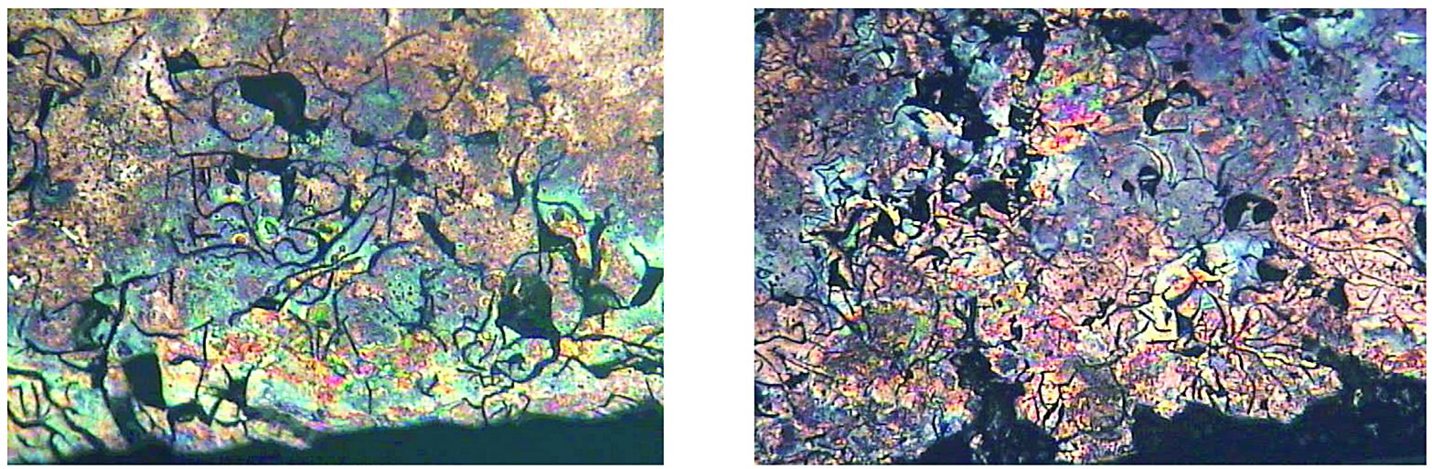
Among other factors, the success in induction hardening of cast irons and repeatability of obtained results are greatly affected by a potential variation of matrix carbon content. This requires tighter control of the process recipe/protocol. An attempt should be made to select a process recipe that would allow avoiding the formation of undesirable transformation products in the as-quenched microstructure. Figure 7 illustrates an example of such undesirable mixed structures.
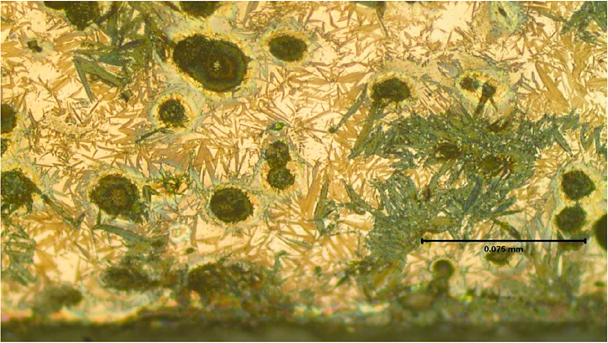

“Friendly” prior microstructure in combination with advanced technology produce fast phase transformations at minimum hardening temperatures with minimized distortion [1,11,12]. For example, the case study provided in [11] reveals achieving almost undetectable camshaft distortion of approximately 3 to 5 microns (based on 1.5- and 2.0-L diesel or regular fuel engines) while applying Inductoheat’s non-rotational technology (SHarP-C Technology). In many cases, this technology eliminates sequential camshaft straightening operation. Figure 8 shows a close-up of the unique design of the SHarP-C inductor (left) and the as-hardened microstructure (right) that reveals a two-phase structure (fine-grain martensite and nodular graphite) with an insignificant amount of retained austenite.
New Technical Resource for Induction Heating Professionals
Space does not permit a discussion of all the intricacies of induction heat treating of cast irons. More information can be found in the 2nd Edition of the Handbook of Induction Heating (Figure 9), which embarks on the next step in designing cost-effective and energy-efficient induction processes. It is intended to reach a variety of readers including practitioners, engineers, metallurgists, managers, students, and scientists.
References
- V.Rudnev, D.Loveless, R.Cook, Handbook of Induction Heating, 2nd Edition, 2017.
- C. Walton, T.Opar, Iron Castings Handbook, Iron Castings Society, Inc., 1981.
- Heat Treater’s Guide: Practices and Procedures for Nonferrous Alloys, ASM Int’l, 1996.
- J.Davis, ASM Specialty Handbook: Cast Irons, ASM Int’l, 1996.
- ASM Handbook, Volume 4D: Heat Treating of Irons and Steels, J.L.Dossett and G.E.Totten (editors), ASM Int’l, 2014.
- Y.Misaka, K.Kawasaki, J.Komotori, M.Shimizu, Fatigue strength of ferritic ductile cast iron hardened by super rapid induction heating and quenching, Mater. Trans., 45(9): 2930–2935, 2004.
- I.Iitaka, K.Sekiguchi, Influence of added elements and condition of graphite upon electrical resistance of cast iron, Reports of the Casting Research Laboratory, No.3, Waseda University, Tokyo, Japan, 1952, p.23–25.
- ASM Handbook, Vol. 4: Heat Treating, ASM Int’l, 1991.
- M.J.Fallon, The surface hardening of cast iron, British Cast Iron Research Association (BCIRA), 1988.
- A.P.Druschitz, S.Thelen, Induction hardened ductile iron camshafts, SAE Report: 2002-01-0918, 2002, p.161–166.
- G.Doyon, V.Rudnev, J.Maher, Low-distortion, high-quality induction hardening of crankshafts and camshafts, Heat Treating Progress, September, 2013, p.59–61.
- V.Rudnev, Induction hardening cast irons, Heat Treating Progress, ASM Int’l, March, 2003, p.27–32


 general practice for CQI-9 and AMS2750E")


