


To increase the hardness of a steel material, there are basically three required steps in the hardening process. Step one is to heat the material, step two is to keep the temperature above a certain hardening temperature level for a certain time (dwell time), and step three is the quick cooling of the part, often referred to as quenching. During the dwell time, which is always higher than 1333°F (723°C), α-iron (ferrite) changes to γ-iron (austenite). Austenite can dissolve a higher amount of carbon than ferrite. Quickly cooling the material after the dwell time leads to a freezing of the carbon in the fine grain structure, creating a body-centered tetragonal structure. This structure is called martensite, and the non-crystallographic structure represents the hard material.
Today, hardness is measured in Rockwell (HRC), Vickers (HV), and Brinell (HB); the most commonly used are HV and HRC. All are based on the resistance of a part to the penetration of a counter body. A test specimen with a defined force for a defined time will leave a mark on the surface of the component to be measured. Typical HRC values for materials can range from 50 to 60 and sometimes achieve values slightly above 60.
Martensite is formed between an upper and lower material-specific temperature range. The higher the cooling rates, the more martensite is created in the material. Martensite, based on its crystal structure, increases the volume of a part, which can cause cracks, tension, and damages in the piece, and it requires a certain amount of rework after the hardening process to achieve the specified mechanical measurements of the hardened part. In almost all hardening techniques known to the industry — e.g., oven hardening, flame hardening, and induction hardening — milling, shaping, and grinding are necessary after hardening. Hence, the necessary material removal, the wear of the tools, and the calculated additional material before hardening add up to a high cost factor.
A Cost-Efficient Process
It is possible to lessen the aforementioned cost factors with the use of laser hardening. However, laser hardening cannot be considered for every application, as it has its limits, too. The following discussion presents comparisons of laser hardening to other applications.
The first example is shown in Figure 1, a 21-ton part that is heated in the oven to create a hardening. Here, it’s important to consider the amount of energy that is deposited into the part and the quick cool-down needed to create martensitic structures. Also, consider the necessary rework, the cost of energy, and carbon footprint. Nevertheless, the hardening was done this way most likely because of the hardening depth required in such a huge part and its use in the industry.
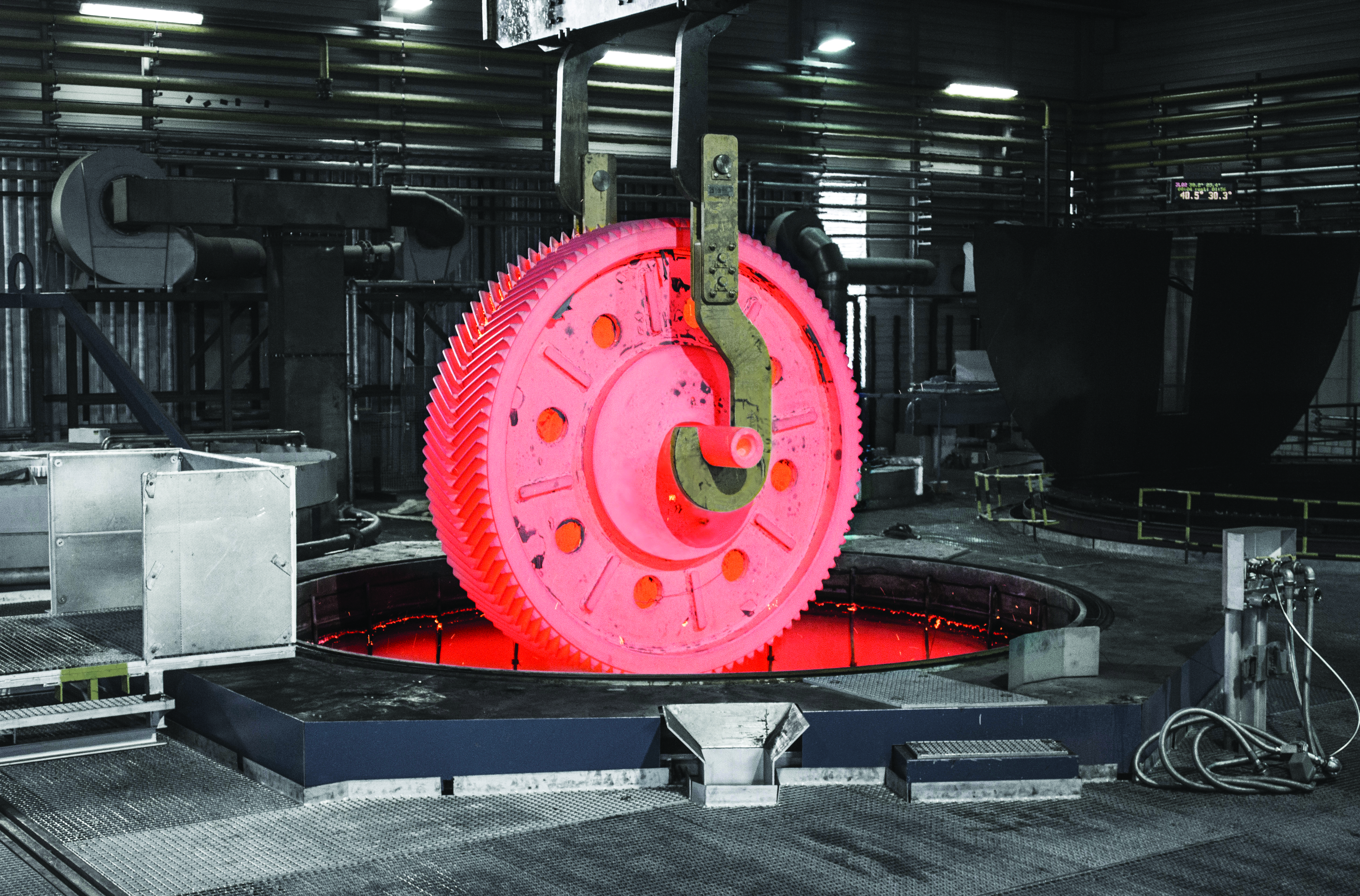
Hardening is applied from the surface to the inner of a part, and the hardening depth depends on the technology applied. In other words, the correct technology should be applied for a certain depth. The example shown in Figure 1 requires a hardening depth of several inches, whereas the laser is limited to 0.03-0.08″. However, the limited hardening depth can be the necessary advantage, as it does not require milling in the hard status unlike oven, flame, and induction. A German OEM using various hardening technologies claims it can save up to 20 percent in the total cost of production after changing from induction to laser just by eliminating the machining in the hard status.
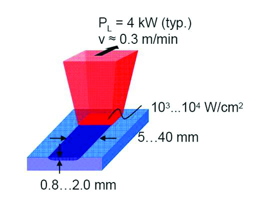
The schematics of laser hardening is shown in Figure 2. A focused laser beam is moved slowly over a section of the workpiece to heat it up quickly, keeping the temperature above hardening level during the dwell time and allowing the part to cool by self-quenching after the laser beam moves on. The high rise and fall time of the temperature with the sharp laser beam is specific, as well as the selective heating of the functional surfaces only. Therefore, distortion is avoided, rework is eliminated or reduced to a minimum, and no specific cooling media is required as the heat conduction of a small amount of energy is easily managed into the part itself. The latter leads to the self-quenching effect. Aerosols, water, or gases are not necessary, which translates into cost savings.
A Fiber Coupled Diode Laser
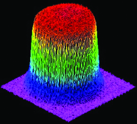
The laser sources typically use a power level from 2 kW upwards, and the industry has seen installations with 15 kW and higher. Most efficient is a laser applied in a top-hat beam distribution (even in all directions) with a wavelength that allows high absorption into the metals treated. This all leads to a fiber coupled high power diode laser, which is the core development and product of Laserline GmbH.
A diode laser with a wavelength in the near infrared light, ranging from 900 to 1100 nm, allows the best absorption in metal — typically a factor of 10 to 15 percent higher compared to other lasers — and does not offer the top-hat energy distribution.
Higher speeds in the overall process are faster and more precise, which saves production time as well.
Laser hardening is not limited to small parts or fine structures; it can be helpful even for bigger structures and heavy-duty parts. Users might assume that the depth of just 0.06″ is not enough, but with the fastest heating and quenching, the hardness is higher and the wear is lower, hence, even big parts should be considered. Some examples from Laserline’s customers — ALOtec Dresden GmbH (ALOtec) in Germany and LaserTherm spol.s.r.o. (LaserTherm) in Czech Republic — are presented in the following section. Both companies are offering job-shop work for hardening as well as turnkey solutions for customers ready to buy a system.
Less Distortion with Laser Hardening
LaserTherm was involved in beds of heavy lathe for processing parts in the range of maximum 12 x 4 x 1 m³ (40 x 13 x 3 ft³) that required hardening of 660 HV (58 HRC) in a depth of > 1 mm (0.04″). Conventional methods such as induction and flame hardening required an over-measure of 0.08-0.12″ and a hardening depth of 0.12-0.20″.
“We have seen a distortion of over 0.08″ per yard length using the conventional methods,” said Ondrej Soukup, managing director at LaserTherm.
After applying finite element calculations in combination with empiric results, the distortion could be reduced to 0.11″ over a total length of 11.9 yards.
“As our calculations from the FEM ended up with 0.12″ distortion, which was applied in pre-machining the bed in soft status, it compensated perfectly and left us with no rework,” said Soukup.
The hardness in this laser-applied example is up to 700 HV (60.1 HRC) and has a depth of 0.04″ with over 660 HV as specified.
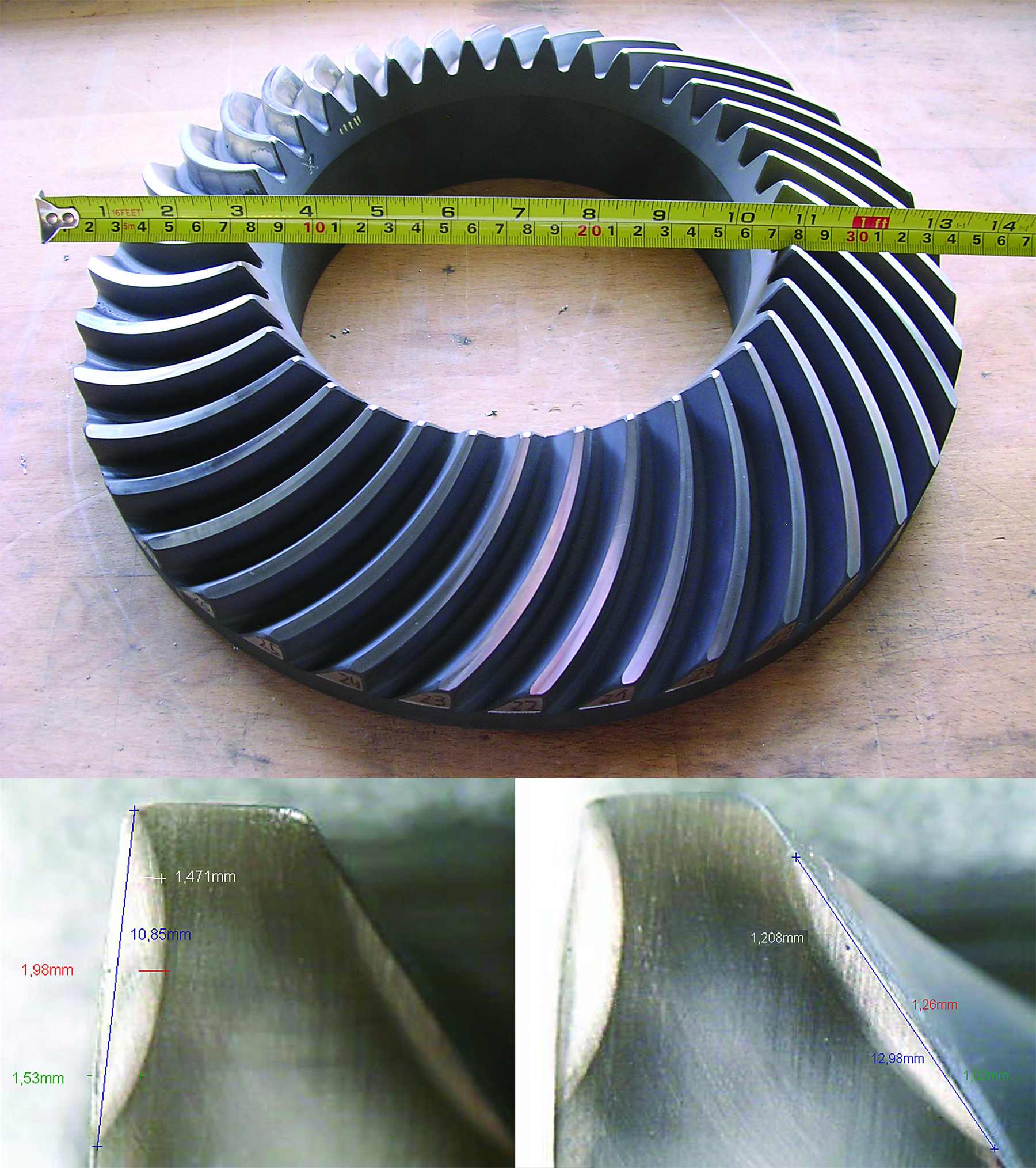
Another example from LaserTherm is the heavy-duty pivot ring of a crane. Figure 4 shows the crane and the position of the gear wheel in question. The wheel is over 14 feet in diameter and weighs 5.3 metric tons. The material is a 42CrMo4, which can be effectively laser hardened due to its 4.2-percent carbon content. Only materials with above 0.2-percent carbon content are to be considered.
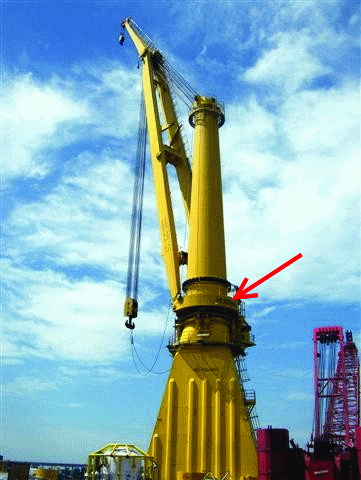
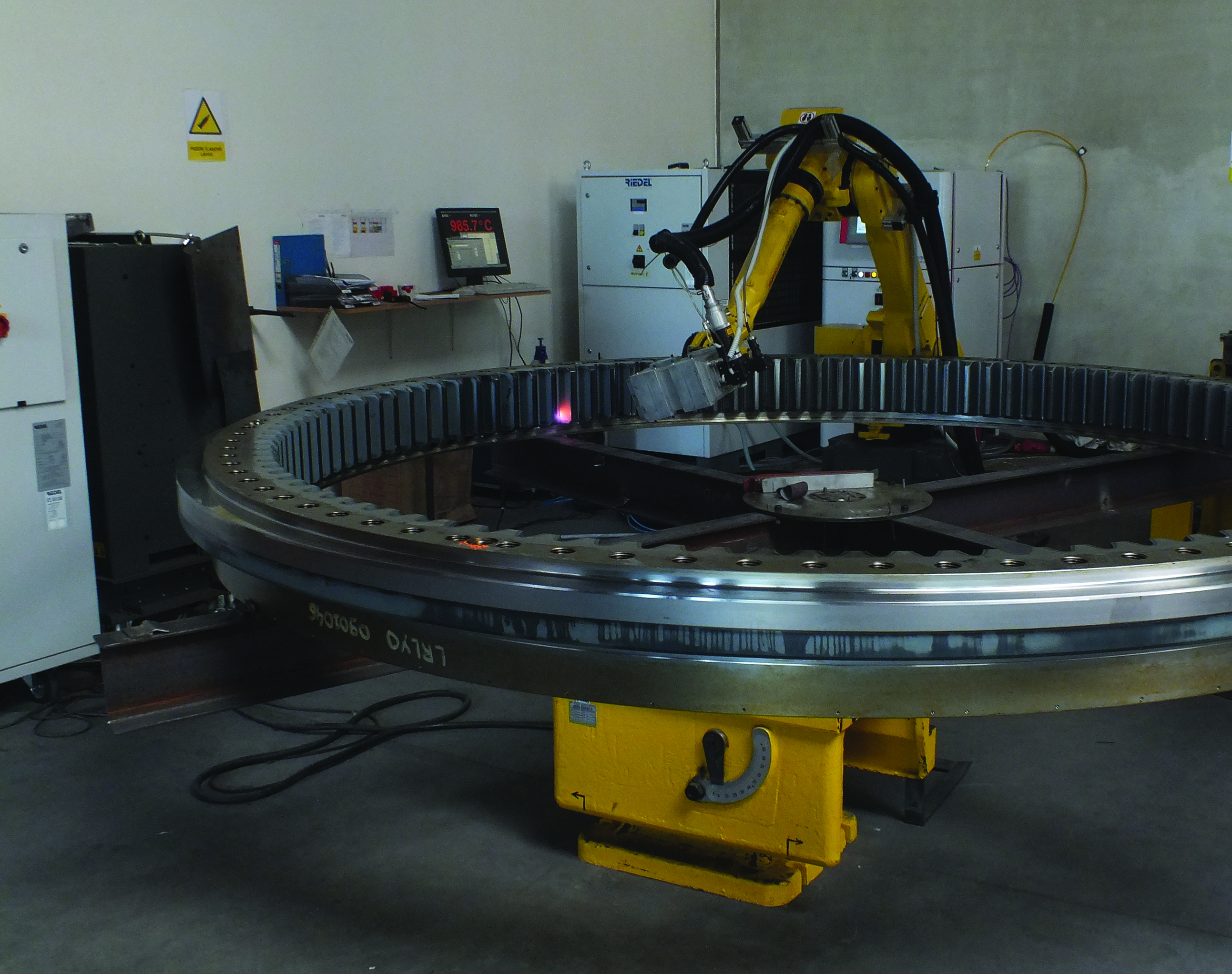
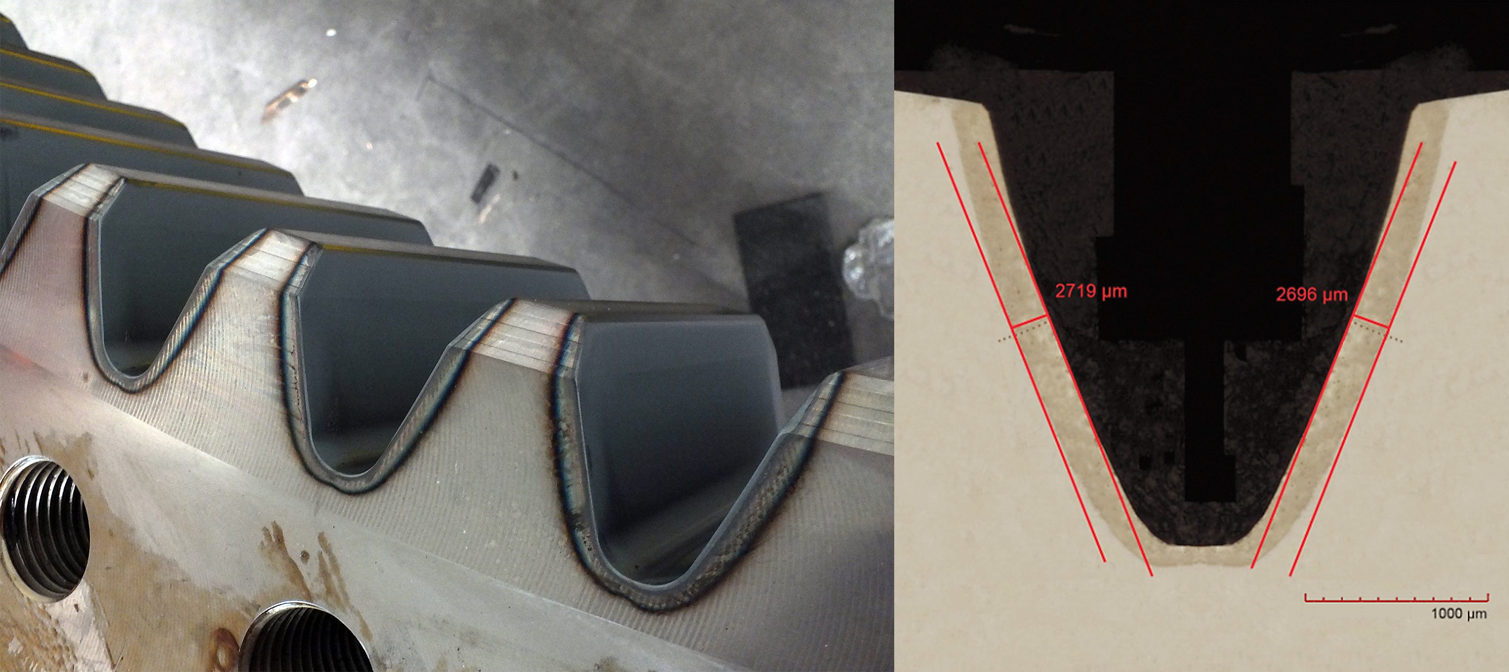
Figure 5 shows the hardening process by laser. Within six hours, the teeth of the wheel are hardened to a hardness of over 520 HV in a depth of 0.08″, reaching a hardness of over 600 HV on the surface. The results are shown in Figure 6 with a cross-section of the gear wheel. The hardness of the base material is only seen in a depth of almost 3 mm (0.12″). The spot sizes of the diode laser were applied by a zoom homogenizing optic, another product from Laserline. The optic allows changing the spot size from the smallest 8 x 8 mm² to the largest 50 x 50 mm² — always keeping the spot in a top-hat distribution and homogenized. This allows LaserTherm to apply the perfect spot size to every geometry and create unflawed results.
“High power diode laser techniques can be applied in many sectors of heavy industry in order to make the manufacturing of machine parts more efficient and to improve its overall quality and productivity,” said Soukup.
Lasers Can Be Adapted to a Range of Geometries
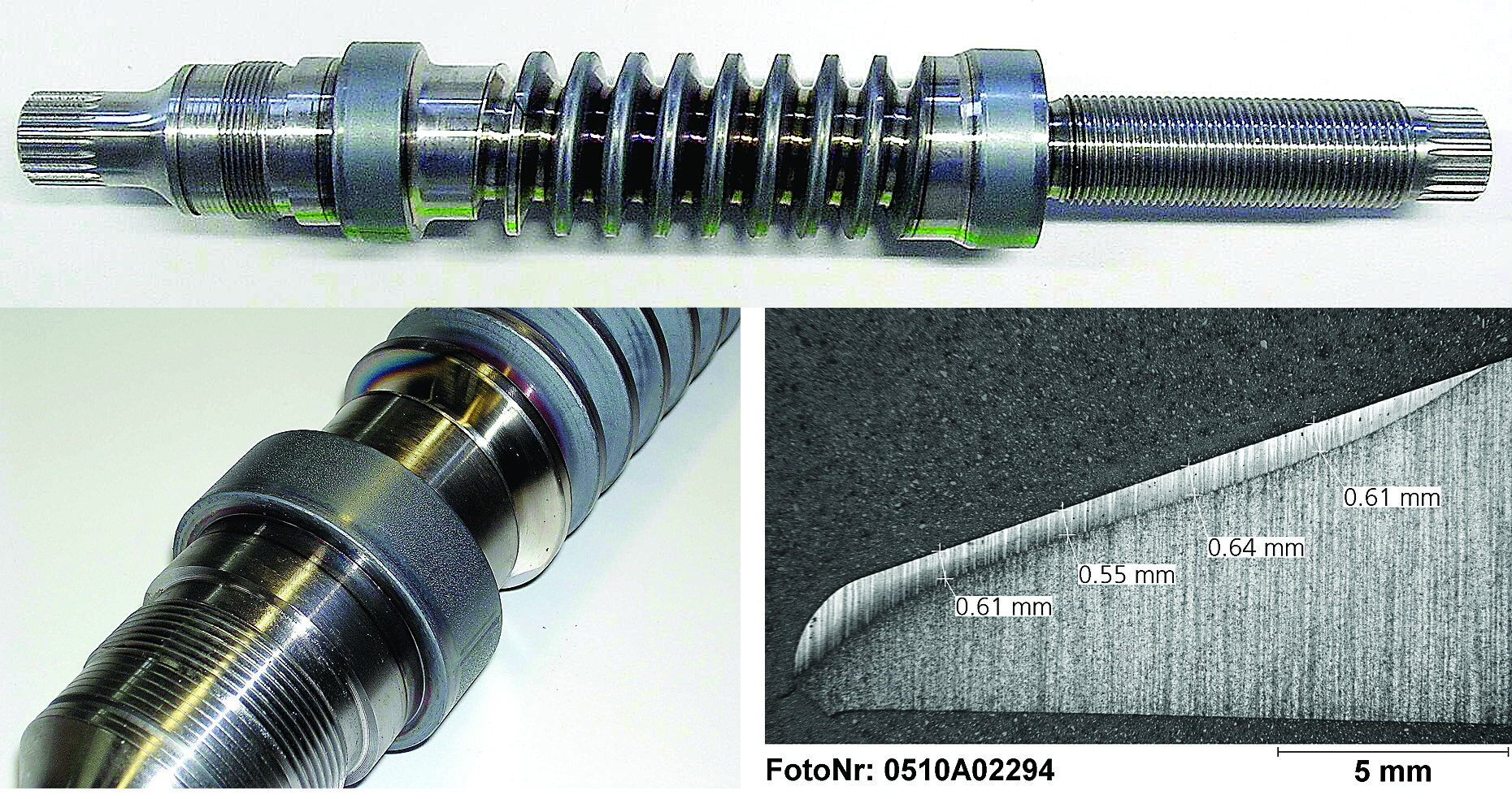
In addition to LaserTherm, ALOtec is also using the diode laser from Laserline. ALOtec offers toothed racks, worm shafts, worm gear wheels, gear shafts, gear wheels, and pinion shafts, as well as conical gear wheels, chain sprockets, and clutch grooves. For this discussion, we selected three examples: the chain sprocket (Figure 7), the worm shaft (Figure 8), and the conical gear wheel (Figure 9). For all of these parts, the low distortion, the selective hardening only where needed, the depth of 0.02 to 0.08″, and the resulting hardness of 60 HRC in all samples in absence of a coolant were results from laser hardening. Some of the parts would not have been possible with any other method; others would have been more costly with non–laser based applications.
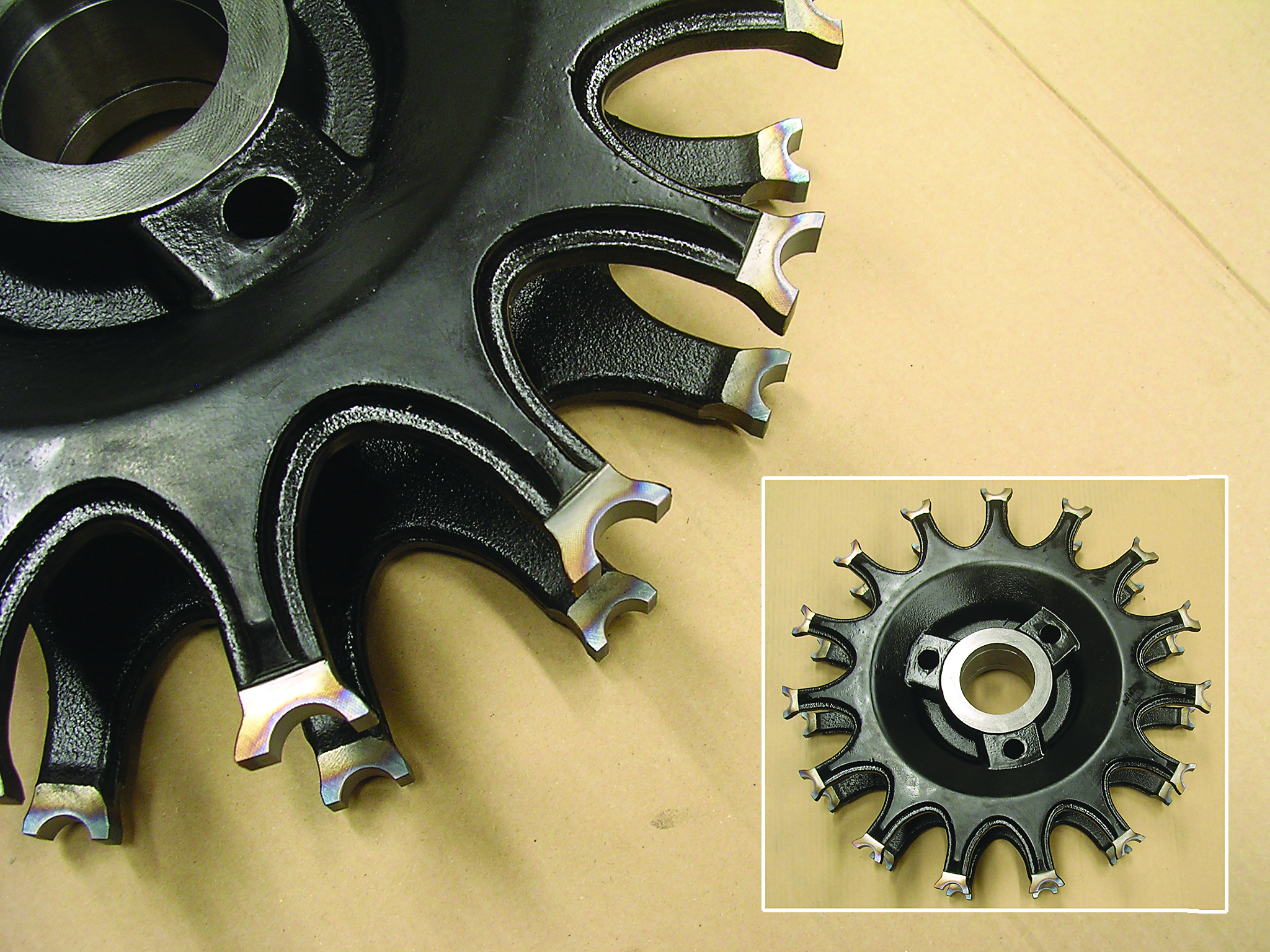
The conical gear wheel achieves a hardening depth of 0.075″, takes 55 seconds per flank, and only requires a laser power of 2 kW. The distortion is not possible to measure, there is no rework, and the wheel is machined to its final measurements before hardening. With the zoom optics, ALOtec would be able to adapt the spot to any version of the wheel.
The complexity of the worm shaft is covered by the freedom of a six-axis robot and an additional turning axis. ALOtec is experienced in applying the laser and its heat to the material. It must be considered that an overlap of the already-hardened section with another heat treatment should be avoided. The martensite will start to fall apart, depending on the material used at temperatures of 300°F and above. Hitting a surface twice will create a soft section.
An advantage of laser hardening is that the laser can be applied selectively, so the operator of the robot or system can ensure that the overlap does not happen. Using the zoom optics and the corresponding power into the spot allows new approaches and unveils new options for customers. In the past, the limit was 4 kW, thus the spot size was limited to approximately 40 x 10 mm², but Laserline now offers lasers up to 25 kW, and it has 40 kW and higher in its labs. With such high power, the spot can be made larger, and where two lines had been necessary in the past, the heat can now be applied in just one path, with a width of 4 inches now possible. This avoids a softened area in the overlap section. Having the 40 kW from the lab at the doorstep of factories and production floors, more applications are possible, and lasers are taking more market share.
As laser hardening is a temperature-guided process, it is highly recommended to apply a closed-loop temperature control to the process, such as a pyrometer or a camera-based system. Applying this closed-loop temperature-guided application allows precise hardening sections, as shown in Figure 7 for the chain sprocket.
Setup and programming is typically part of the three-day commissioning for a turnkey solution.
“Today’s diode lasers are simply black boxes in a hardening system, covered with warranties up to five years for their diodes, installed in less than three hours, and have a standardized interface,” said Dr. Hensel, founder and CEO of ALOtec.
Conclusion
With laser hardening, designers and engineers as well as managers and operators on the production floor have the option to optimize their heat treatment processes. Rework in the hard status can be eliminated or reduced to one grinding process. Lasers can harden selectively and avoid distortion and high levels of over-measure. Diode lasers themselves can be adapted to almost all geometries and have the best-suited beam and wavelength combined with an unparalleled wall plug efficiency to reduce the carbon footprint in production. Finally, these lasers can be guided by optical fibers to make them a versatile and flexible tool, which can be combined with both robots and CNCs, and existing hardware can be upgraded.


 general practice for CQI-9 and AMS2750E")


