


Heat-treating and metallurgy are topics that attract the overwhelming interest of attendees of technical conferences and are written about in numerous articles. However, a subtopic of the genre that is too often overlooked and is just as critical is welding.
Furnace casings and their internal components rely on welding to connect subassemblies. Steel structures that support the refractory are fabricated from steel plate that in the case of atmosphere furnaces is generally 3⁄16˝ to ¼˝ thick. Structural members such as I-beams and channels are also welded to form the rigid skeleton providing the integrity to keep the structure square and aligned for successful operation, and to create the stiffness required for transport from the OEM to the final destination — which can be an ocean away.
Welding metal can be categorized by the following four primary methods:
Shielded Metal Arc Welding (SMAW) or ‘stick’ welding was the early process employed for decades for steel, aluminum, and other metals. It consists of a ferrous or other applicable electrode rod coated with flux, a carbonate and silicate material similar to slag in the steel making process. The molten slag, being less dense than the metal, floats on top of the weld bead protecting it from oxidation. Pros: It’s a forgiving process and can be used for many different thicknesses of metal. Cons: It’s a slow and messy process. The method creates slag and metal splatter that must be mechanically removed before adding additional passes and for appearance. As one 12-inch long welding rod or stick is consumed, the welder must stop and use another. The resulting stop/start crater creates potential failure points when not treated properly.
Metal Inert Gas (MIG) eliminates the flux and uses a continuously fed consumable wire as the filler metal. However, for mild steel, a mixture of 75 percent argon and 25 percent CO2 provides the shielding to reduce potential oxidation of the weld bead. Where stainless steel is concerned, a tri-mix of 90 percent helium, 7.5 percent argon and 2.5 percent CO2 is used. Pros: MIG is the fastest process since the welder does not have to stop and replace the weld rod. No cleanup is required. Cons: The welding area must be protected by curtains or otherwise shielded from room air currents that can displace the shielding gas without the welder’s knowledge resulting in porous (leaky) welds and reduced structural strength.
TIG (Tungsten Inert Gas) employs a hand-held tungsten torch, as it’s called, held like a pencil or air brush in one hand while a manually fed filler rod is melted by the tungsten arc. The torch also provides the shielding gas to protect the weld from oxidation. The filler rod has no flux covering but is longer than the typical 12-inch long stick rod, so fewer stop/start craters result. TIG welding is generally used for thin sheet metal where the power to the arc is kept low so the arc does not melt through the material being welded. Like MIG, the shielding gas is selected according to the metal being welded. It’s a slow process where the filler rod is manually applied to control the quantity of weld metal required. Pros: Highly controllable and can be very precise for application such as jewelry making and welding extremely thin components. Cons: A slow process. Can be difficult to master. TIG is sometimes referred to as heliarc welding.
Flux-Cored Arc Welding (FCAW) combines the benefits of stick welding and the MIG process and is the most forgiving welding method. Continuously fed like the MIG process, the consumable wire is filled with a flux in addition to using inert gas. It’s a fast process but provides the additional oxidation reducing result of flux. Pros: Fast, forgiving, and easy to learn; produces high-quality weld bead. Cons: Requires slag cleanup due to spatter.
Welding is a lot more than striking an arc and laying down metal.
The purpose of welding is twofold: Connect one or more subassemblies in a seamless manner. To eliminate fluid leaks between assemblies or components where mechanical fasteners cannot eliminate gas or liquid leakage or provide continuous connected strength where rivets or threaded fasteners can’t.
The most critical applications for welding are for vacuum systems, pressure vessels, and petrochemical applications. Vacuum furnaces, as well as non-heated low-pressure structures, must have weld integrity of strength and leak tightness. MIG welded components can look completely acceptable from a physical appearance but can have significant leakage through micro-porosity. Quality tests for vacuum systems consist of helium testing, in which a helium mass spectrometer measures the quantity of helium gas that migrates through the welds and other mechanical fasteners. Where pressure vessels are concerned, welds are commonly X-rayed to detect internal porosity or other imperfections. For example, when heat-treating furnaces are indirectly gas fired the burner fires into radiant tubes straight or U shaped. Heat-resisting alloy U tubes are centrifugally cast and a statically cast return U bend is welded to each straight tube. After welding, each tube assembly is pressure-tested to find and repair any leaks.
Testing for weld quality after welding is complete is typically done by liquid penetrant or dye testing. The procedure consists of the following:
- Thorough removal of all remnants of slag, and then make sure the weld is completely dry.
- Spray or brush the dye penetrant on all welds and areas affected by the welding heat.
- Let the penetrant reside on the weld for the appropriate time per the penetrant instructions.
- Thoroughly wipe away the residual penetrant from all areas of the weld.
- Spray the developer onto the weld area and let stand again per the instructions.
Any surface imperfections will result in the penetrant via capillary action to discolor the developer revealing cracks and/or porosity. The downside of this technique is it only reveals surface anomalies, not subsurface issues.
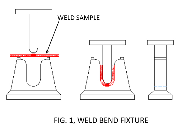
When a weldment’s strength is important — and it always should be — two primary destructive tests are completed to determine the weld’s integrity. The first is a simple tensile test in which two approximately two-inch wide by four-inch ¼˝-thick steel sections are butt welded together. After cleaning, the welded sample is pulled apart to failure. The failure must not occur in the weld bead but in metal plates or the heat affected zone (HAZ), which is the area where the weld connects to the ¼” plate. The second test is for ductility. It consists of placing a similar test sample on a U-shaped fixture and the sample is pushed into the cavity creating compressive and tensile stresses on opposing sides of the weld bead. Figure 1 is a typical bend test fixture.
Just as the microstructure determines the successful result provided by heat-treating of metal, the microstructure of the weld is of uppermost concern for metallurgists. As discussed in previous columns, all wrought ferrous alloys such as sheet, plate, rod, bar, etc. begin as castings. A weld is a casting and as such retains all of the benefits and disadvantages of all castings, i.e. a brittle nature, low ductility, and subject to fatigue failure in certain applications and high strength.
One of the critical skills possessed by good welders is the ability to set the appropriate power settings so the weld and surrounding metal do not overheat. The two negatives produced by too high a heat setting are undercutting and the exaggerated direction of the dendrite microstructure from the root of the weld to the surface. Both examples are shown in Figure 2a.
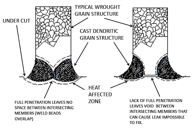
Undercutting produces a notch in the HAZ that can reduce the already increased potential for fatigue failure of the weld’s cast structure. The directional dendritic grain structure from root to surface produced by high heat tends to enable cracks to follow along the longitudinal grain boundary unimpeded by the smaller grain structure of the wrought metal. Being a casting, overheating also allows the concentration of carbon-forming iron-carbide Fe3C in the grain boundary due to the slower cooling of the weld area.
Conversely, if the power to the electrode is too low, producing a cold weld, it will lack the penetration required to fill the material cross-section, weakening the assembly and possibly creating a void at the root of each weld bead — disastrous for vacuum systems as the void can produce a leak from trapped air that’s impossible to find. Figure 2b shows an example of a less-than-full penetration weld.
Although the four welding techniques discussed above satisfy the overwhelming applications today, there are other specialty processes that have been developed. They are as follows:
LBW (Laser Beam Welding) is a technique that is used where near-finished machined components are joined with or without a filler metal. The weld bead is small in comparison to MIG, TIG, or stick processes. A shielding gas is used or the operation can be performed in purged enclosure. Generally, LBW is automated with a robot, as the process can be very fast and must be precise due to the small arc and resulting weldment.
Friction welding (FW) really isn’t welding at all. It’s sometimes called forge welding since the parts to be joined are pressed together with extremely high force and the mechanical motion between the parts creates high heat concentration but not enough to melt; instead the parts are more or less forged together.
SAW (Submerged Arc Welding) is an automated form of SMAW; however, the flux is added separately in granular form, not attached to the ‘stick,’ while the filler metal is fed. It’s primarily used when the steel plate is thick and requires uninterrupted welding. Always performed horizontally, the electrode can move relative to the part in a straight line or the part can rotate under the electrode when pipe sections are connected. The granular flux is automatically fed from an annular opening surrounding the wire electrode. When the seam to be welded is circular, such as around the circumference of a pipe, the weld takes place at the very top. The flux slides off the weld as the pipe rotates. Molten slag is created where the flux contacts the weld and helps to remove impurities. However, the flux that isn’t melted slides off the weld as the pipe rotates. Since slag is created, it must be removed before additional passes can be applied. Oil pipelines and wind turbine towers are typical recipients of the SAW process.
Welding, in essence, is a fastening method just like bolts, nuts, and the like, but in which a continuous connection is required for either strength or to prevent leaks. However, bolts, screws, and other threaded fasteners go through a quality check for strength traceable to a standard; a weld’s quality is more subjective, relying only on the competence of the technician.


 general practice for CQI-9 and AMS2750E")


