


In this column, I will discuss agitation by submerged jets.
Common methods of agitating quench tanks, and other types of tanks, are by sparging or air or by submerged jets.
Air Sparging and Submerged Jet Agitation
Agitation of simple configuration quench tanks is often cost constrained. A simple agitation scheme is needed to achieve the necessary amount of agitation, while keeping costs low. Proper agitation is critical to achieving part properties and low residual stresses [1].
Air Sparging
In this method, compressed gasses such as compressed air are introduced into a quench tank. The expansion and rise of the air bubbles cause rapid motion and displacement of the quenchant. While this method may be acceptable for water or brine quenchants, it is not suitable for oil quenchants.
In this type of agitation, when a gas is injected into a liquid, there is a gas core (either bubbles or jet) surrounded by liquid circulating around the gas core. As the velocity is increased, a two-phase zone of turbulent mixture of gas and liquid is formed around the gas core. Formation of jet flow is influenced by the gas velocity, nozzle geometry, liquid properties, and the submersion depth.
For air nozzles, there are two regimes: bubble and jet [2]. For most applications, bubble formation occurs at low velocities, and transition to a jet flow occurs as the velocity of the submerged jet increases. For small nozzles, the gas jet requires a higher velocity to form. As the viscosity of the fluid increases, the formation of a gas jet is slowed. Generally, the jet length is linearly proportional to the jet exit velocity.
Use of air agitation is easy to implement, as it is a matter of piping, regulators, and valves. However, use of compressed gas is not cheap. As an estimate, many companies estimate that compressed gas costs between $0.30 – $0.50 per 1,000 cubic feet of air [3]. While it is difficult to estimate usage due to the many different types of possible configurations, estimates can be drawn from product literature (Figure 1) [4].

The use of air agitation is acceptable for water and brine solutions. However, foaming may become a serious problem, requiring the use of defoamers. Use of air agitation is not recommended for oil quenchants, as the presence of air would result in thermal oxidation of the oil. There is increased potential for severe fires when air agitation is used with oil quenchants. Use of air agitation with polymer quenchants is also not recommended. First there will likely be problems with foaming. This can cause problems with quenching and the formation of soft spots on the parts. There is also the problem of thermal oxidation degradation of the polymer quenchant. The use of an inert gas, such as nitrogen, is cost prohibitive.
Submerged Jet Agitation
In submerged jet agitation, a series of small nozzles is submerged in the tank, and the quenchant is pumped through these nozzles (Figure 2) using a centrifugal pump. The motion of the quenchant through the nozzles provides the agitation.
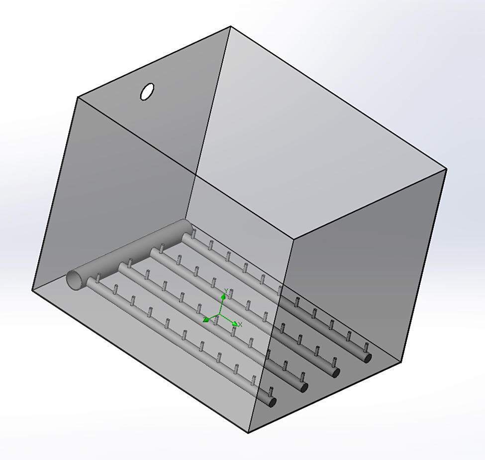
This type of mixer can be in many different types of arrangements. Typically, these nozzles are arranged in a header, and fed from a central manifold. Because of the complexity of examining multiple jets, our discussion will focus on a single jet.
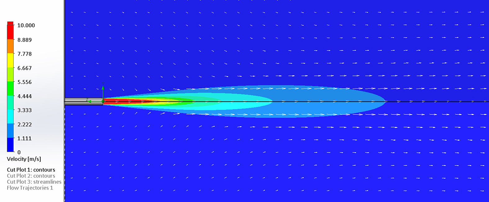
Figure 3 illustrates a typical pattern of a jet [5]. The radius for the jet (Rj) at the centerline distance (x) from the nozzle can be calculated from [6]:
 The velocity profile and spread of the nozzle pattern is shown in Figure 4.
The velocity at the centerline distance (Ucj) for x/Dj >8 can be calculated [6]:
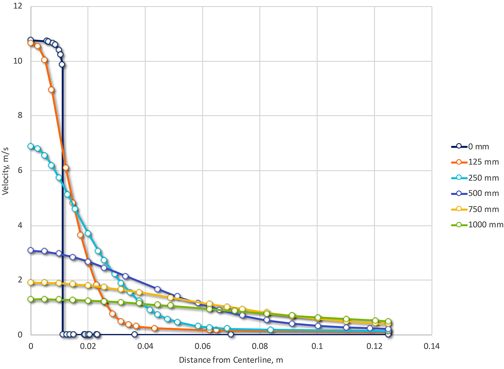
 Where Dj is the diameter of the jet at position j, and U0 is the velocity of the jet at the orifice (R0). This is shown in Figure 5.

To optimize mixing, the entrainment of the quenchant into the jet should be maximized. Rushton [7] showed that the maximum entrainment occurred approximately 17 jet diameters from the nozzle. Tatterson [8] reported that the fluid entrainment decayed to zero when the centerline distance exceeded 100 diameters. Therefore, large jets should be used for large tanks, and the nozzles should be placed within 17 diameters (maximum) of the surface being quenched.
To achieve uniform quenching, the jet plumes should overlap. Using the equation for the radius of the plume [6]:
 Substituting 17d for x (d is nozzle diameter) we obtain:
 as the maximum spacing for nozzles to achieve the desired overlap. Using a 25 mm nozzle diameter example, then the maximum nozzle spacing is 98.6 mm.
Conclusions
In this short article, I have discussed the use of air sparging and submerged jet nozzles for the use of agitation. While not as efficient as agitators in terms of flow versus power consumption, sparging is useful for water and brine applications, and submerged jets are useful for small tank applications to achieve necessary flow rates.
If you have any questions or comments regarding this column, or have any suggestions for further columns, please contact the editor or me.
References
- G. Totten, C. Bates and N. Clinton, Eds., Handbook of Quenching and Quenchants, Metals Park, OH: ASM International, 1993.
- S. R. Syeda and A. M. Ansery, “Formation and Development of Submerged Air Jets,” J. Mech. Eng., vol. ME 44, no. 2, pp. 137-141, December 2014.
- U.S. Department of Energy, “Energy Tips – Coompressed Air,” Department of Energy, Washington, D.C., 2004.
- Nex Flow Air Products Corp., “Air Nozzles and Jets,” Richmond Hill, ON, Canada, 2022.
- H. Fossett and L. E. Prosser, Proc. Inst. Mech. Eng., vol. 160, pp. 224-251, 1949.
- R. G. Folsom and C. K. Ferguson, Trans. ASME, vol. 71, pp. 73-77, 1949.
- J. H. Rushton, Petrol. Refin., no. August, pp. 101-107, 1954.
- G. B. Tatterson, Fluid Mixing and Gas Dispersion in Agitated Fluids, New York, New York: McGraw-Hill, 1991.


 general practice for CQI-9 and AMS2750E")


