


Surface hardening heat treatments are popular in the manufacture of steel products as a means of significantly improving strength and fatigue resistance and mitigating wear [1]. In the production of bearing components, manufacturers know it is important to control the case depth of the hardened surface layer to ensure safety and reliability. Most current state-of-the-art solutions for hardening depth measurement are based on a statistical sampling approach using the inspection of certain selected characteristics, followed by various destructive testing methods. However, some well-known nondestructive methods — such as eddy current, ultrasonic inspection and, more recently, Barkhausen noise techniques — have also been explored to determine hardening depth [2-3].
 Nondestructive methods reveal hardened depth based on the material property differences, such as hardness and residual stresses, between the surface hardened layer and the core. Nondestructive solutions can be cost-efficient and can be applied to the entire production process without destroying valuable components. Each nondestructive method has demonstrated success in some specific applications. But nondestructive measurement of case depth is also a challenging task that can be significantly affected by surface condition, microstructure, grain size, and geometry variation. Each of these methods has advantages and disadvantages [2-4].
Some of the recent developments in nondestructive case depth measurement are presented below:
Electromagnetic Case Depth Measurement
The conductivity and permeability of bearing products change along with heat treatment and the hardening process. Therefore, case depth can be evaluated nondestructively by measuring characteristic differences in the bearings’ electric and/or magnetic properties using electromagnetic methods [3]. The eddy current method is the most highly developed electromagnetic nondestructive technique applied to case depth measurement thus far. Traditional single frequency, multi-frequency, and pulsed eddy current methods have all been studied and reported for hardening depth measurement [5-7].
Another electromagnetic technique, the Barkhausen noise method (also referred to as the micromagnetic method), has been investigated to determine hardening depth as well [3]. Barkhausen noise measurement is sensitive to stress and microstructural changes and is based on the principle of inductive measurement of a noise-like signal generated when a magnetic field is applied to a ferromagnetic material. Barkhausen noise measurement has been studied and successfully correlated with hardness and case depth [3]. Other related approaches, including alternating and direct current potential-drop methods, have also been explored in hardening depth measurement [4].
Eddy Current Method
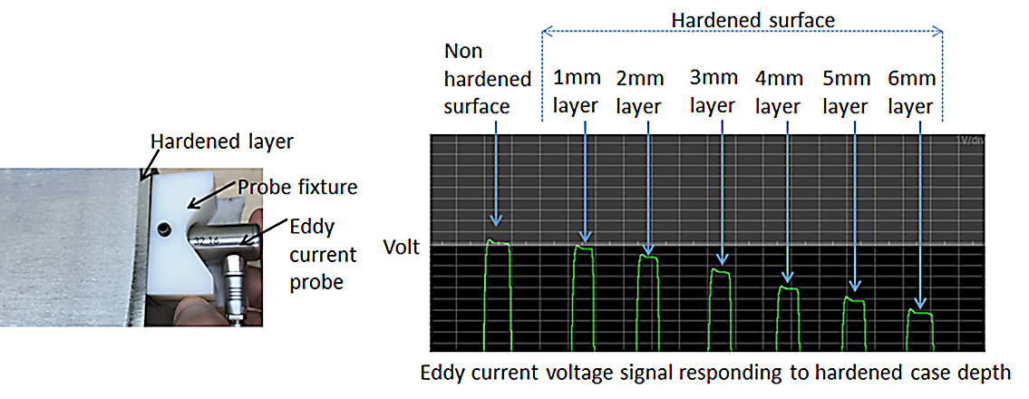
When surface hardness is low, the steel microstructure exhibits high permeability with high eddy current density; as a result, substantial magnetic flux is induced. Conversely, when surface hardness is high, the permeability drops and the eddy current density decreases accordingly. The induced magnetic flux that accompanies high surface hardness is less than that induced at low surface hardness. As a result, the voltage signal seen in Equation 1 that is determined by the magnetic flux becomes lower in accordance with the hardened layer depth [7].
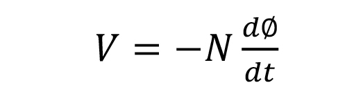
where V = voltage signal of eddy current method; N = number turns of eddy current coil; Φ = induced magnetic flux.
The single frequency eddy current setup for hardened layer measurement and some corresponding signals are shown in Figure 1.
The critical parameter of the eddy current method is the eddy current penetration depth (also called skin depth), which is determined by frequency and material properties, as shown in Equation 2.

where f = frequency; µ = permeability; σ = conductivity.
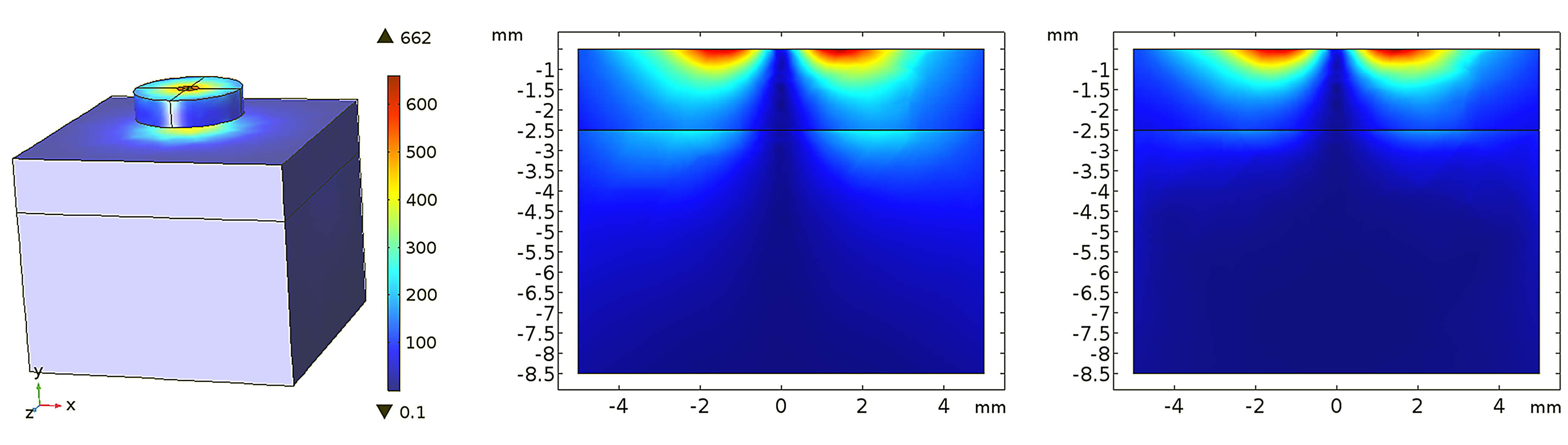
As the frequency increases, the induced eddy current is more concentrated near the surface. This principle is demonstrated in Figure 2, where an eddy current probe has been placed above a steel surface with a hardened layer. The lower frequency generates deeper penetration; thus, a lower frequency is preferred in order to perform deeper case measurement with superior sensitivity. On the other hand, higher frequencies produce strong sensitivity when the hardened layer is thin. As a result, multi-frequency eddy current methods have been explored to accommodate these observations [6-7].
Ultrasonic Case Depth Measurement
The metallurgical properties of surface induction-hardened medium- and high-carbon steel components can make them amenable to nondestructive case depth measurement using ultrasonic techniques. Development of this test method was explored by Good [8] in the early 1980s. Further refinement of the technique occurred in the early 1990s at the Fraunhofer Institute (IZFP) and Pacific Northwest National Labs, which led to respective patents [9-10]. Developments critical to industrial use included appropriate test frequencies, signal averaging, and filtering methods to allow consistent waveforms to be obtained from the ultrasonic signal.
The measurement principle is based on the propagation of ultrasonic shear waves applied at an angle to the test surface. The shear waves produce a backscattering effect as they reach the case/core transition because of the differences in the microstructure’s acoustic impedance properties in this zone.
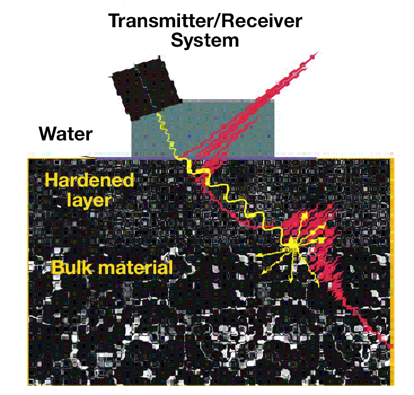
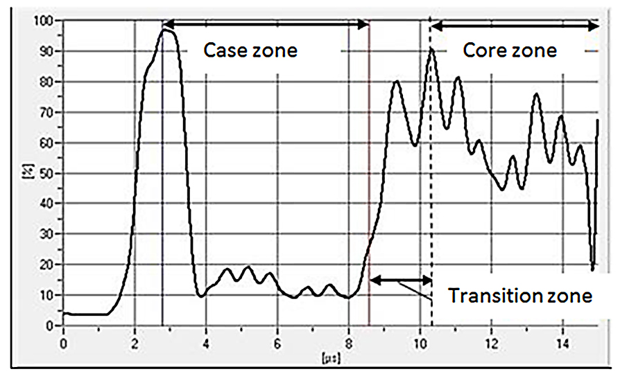
In order to obtain a reliable signal from which a measurement can be made, a few conditions must be satisfied. First, the hardening must be deep enough so that the front surface and backscattered peaks are sufficiently separated in time. This assures distinct peaks from which time-of-flight can be calculated. Second, the transition zone between the case and core must be sufficiently discrete such that the backscattered peak is above noise levels (Figure 3) [11]. A good response is achieved by induction surface-hardening a component with an unhardened core, where the minimum depth of hardening is between 1.5 and 2 mm. In this instance, the fine-grained martensitic case zone is in sharp contrast to the coarse-grained ferrite/pearlite microstructure of the core. This condition results in a distinct backscattered signal peak (from surface hardening Figure 4).
Surface treating processes that are not suitable candidates for ultrasonic measurement methods include shallow hardening processes such as nitriding, diffusion hardening processes such as carburizing, and relatively slow conductive surface heating processes that produce a wide transition zone.
The depth of hardening is determined by the relationship:
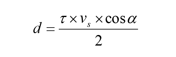
where τ = transit time from the front surface to the beginning of the backscattered peak; νs = velocity of sound in steel; α = angle of sound incidence through the hardened zone.
Variations and errors in measurements may also be introduced by metallurgical conditions such as large amounts of secondary phases (e.g., retained austenite), segregation, and large or varying grain size in the hardened zone. The influence of these conditions on the ultrasonic signal is a function of the test frequency. Maximum attenuation and undesirable scattering occur when the feature dimensions approach the wavelength of the ultrasound.
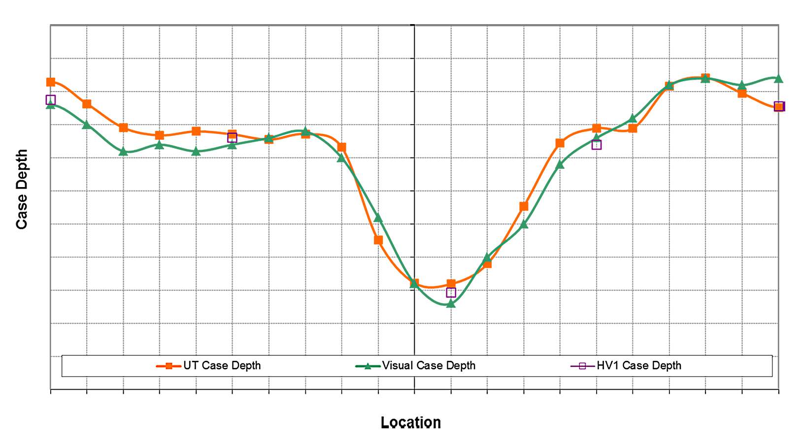
In any discussion on case depth measurement, it is necessary to define the reference method. This can vary depending on applicable standards, products or customer requirements [1]. One of the more common approaches is a specified hardness value to a measured depth. Since ultrasonic backscattering is typically dominated by microstructure effects rather than hardness itself, it is reasonable to assume that a measurement correction might be necessary to correlate these methods. After correction, good correlation between backscattered, visual, and hardness measurement methods is demonstrated, as shown in Figure 5 [12].
Nondestructive case depth measurement has enabled significant cost reductions by reducing or eliminating destructive analysis. This is especially true for large and complex parts where destructive sampling is prohibitive. Successful nondestructive inspection applications are contingent on understanding the details of the material’s condition as well as the limitations of the test method.
References
- Rothleutner, “Metal Urgency: Case Depth Determination,” Thermal Processing, March-April, 2018.
- Y. Salchak, et al., “Method of case hardening depth testing by using multifunctional ultrasonic testing instrument,” Materials Science and Engineering, Vol. 81, 2015.
- M. Deveci, “Nondestructive determination of case depth by Barkhausen noise method,” Master of Science thesis, Tampere University of Technology, May 2016.
- C.X. Zhang, “Assessment of depth of case-hardening in steel rods by electromagnetic methods,” Iowa State University, 2009.
- R. Palanisamy, “Prediction of eddy current probe sensitivity for the sizing of case depth in ferrous components,” IEEE Transactions on Magnetics, Vol. 23, No. 5, September 1987.
- J. Cuffe, et al., “Eddy Current Measurement of Case Hardened Depth of Steel Components,” 17th World Conference on Nondestructive Testing, 25-28 October, 2008.
- A. Banno, “Development of hardening penetration depth evaluation technique,” JSAE Congress (Autumn), 27 October 2004.
- M.S. Good, et al., “Evaluation of Feasibility for the Ultrasonic Measurement of Case Depth in Case Hardened Steels,” technical report, http://www.dtic.mil/dtic/tr/fulltext/u2/a117901.pdf
- Herbert Dipl Phys Willems, “Apparatus for non-destructively measuring the thickness of a hardened layer,” Patent DE4239159C2.
- M.S. Good, et al., “Ultrasonic material hardness depth measurement,” Patent US5646351A.
- W. Theiner, et al., “Process Integrated Nondestructive Testing of Ground and Case Hardened Parts,” Fraunhofer IZFP, PINT NDT — ECNDT, Barcelona, 2002.
- Internal Timken research report.


 general practice for CQI-9 and AMS2750E")


