


Gears are one of the critical components that determine the capability and reliability of drive systems. Thus the tooth root load-carrying capacity is one of the determining factors in gear design. Continuous demand for higher efficiency, increased load-carrying capacity and endurance life, while at the same time, ensuring smaller size and low costs, increasingly often make the solid expertise of fatigue mechanisms of gears indispensable. In addition to the strength of the material itself, the existing state of stress can significantly influence the tooth root load-carrying capacity and the associated fracture mode.
According to the current state of the art, case hardened gears for industrial gearbox applications often are peened for the cleaning process. Along with the effects of cleaning, peening processes also substantially affect the tooth root load-carrying capacity. Additionally, controlled shot-peening processes lead to an increase of the tooth root load-carrying capacity up to more than 15% [3] compared to blast cleaned gears. Based on extensive experimental investigations on gears different kinds of fracture modes can be observed depending on the present state of stress. According to the current state of knowledge it must be distinguished between breakages with an initiation of fatigue cracks on and under the surface. Especially those breakages with an initiation of cracks under the surface have a negative effect on the tooth root load-carrying capacity in the range of high cycle fatigue. The scope of this research project was to increase the knowledge of the tooth root load-carrying capacity of cylindrical gears with different residual stress conditions, especially in the range of high numbers of load cycles up to 100 · 106. Therefore, an extensive program of gear tests in pulsator test rigs has been carried out to verify on the one hand the different types of tooth root fracture modes and, on the other hand, the associated dominating influences on high cycle fatigue of gears.
Internal Fracture Mode In The Tooth Root
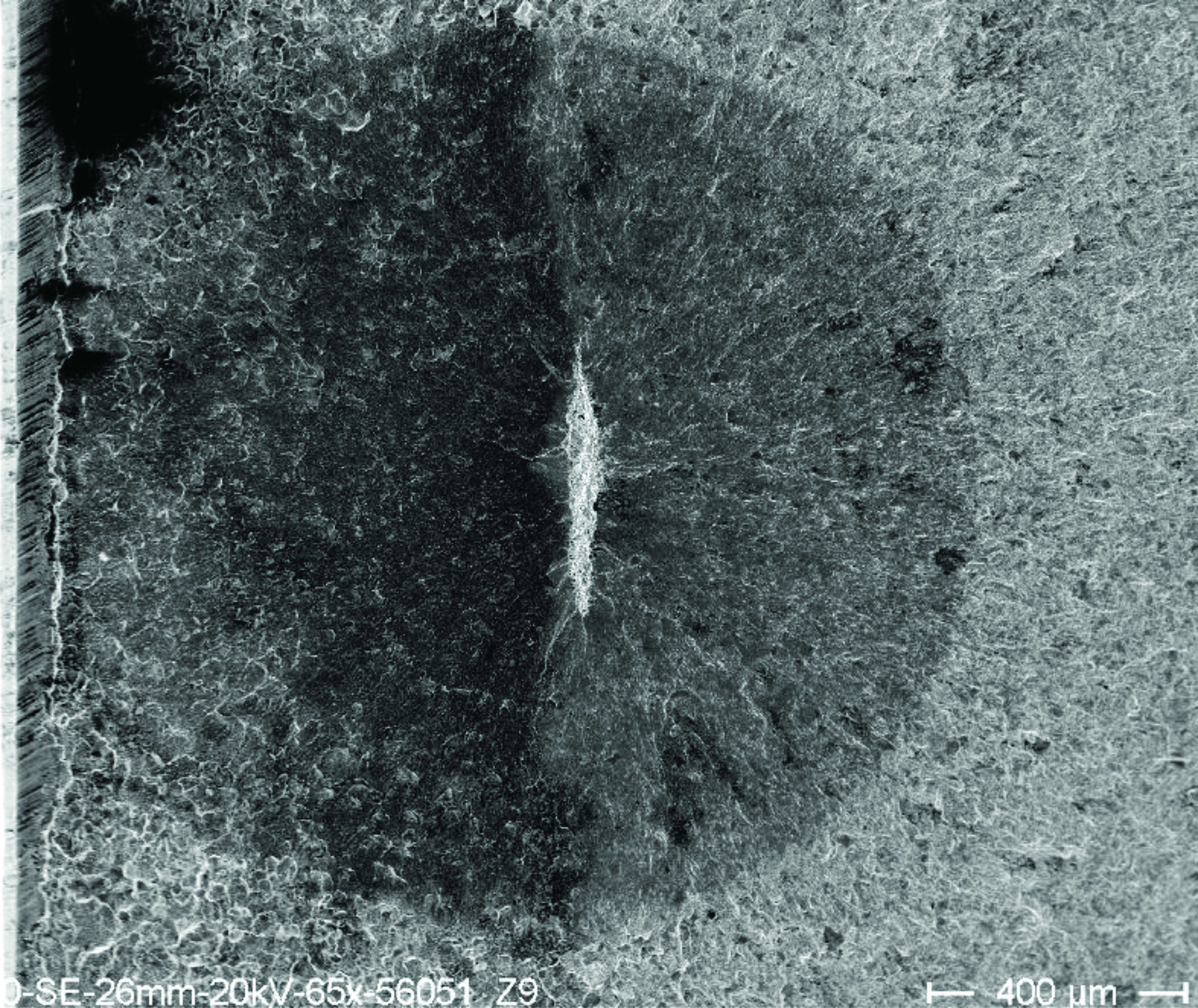
Due to common experience of tooth root bending tests in pulsator test rigs, the endurance limit of the tooth root fatigue strength is usually considered to be 3 · 106 load cycles. As a result, suitable standard tooth root bending tests set the endurance limit at which a test is meant to be graded as fatigue resistant to 3-6 · 106 cycles. In current and completed studies on tooth root load-carrying capacity at FZG, especially on case hardened gears, increasingly frequent tooth root breakages were found that occurred in and above the range of these ultimate numbers of cycles. Analysis of corresponding fracture surfaces show that these damages in the range of high numbers of load cycles often initiate from small inclusions or microstructural defects in the material. Similar damage patterns determined on simple specimens exhibiting a small bright spot at the crack origin are well known from technical literature, the so called “fish-eye” (Figure 1).
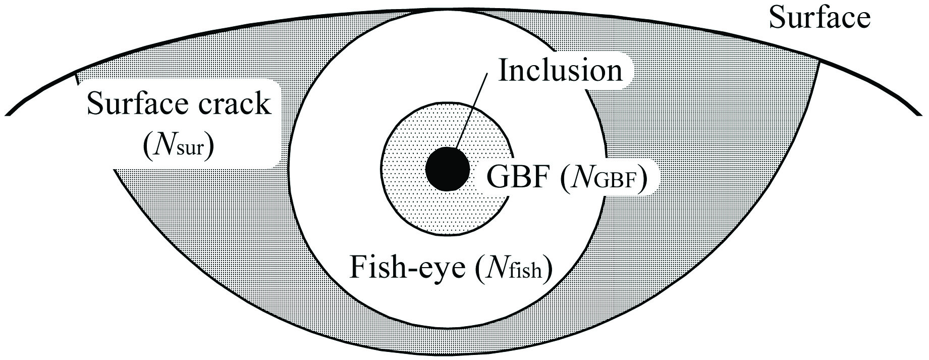
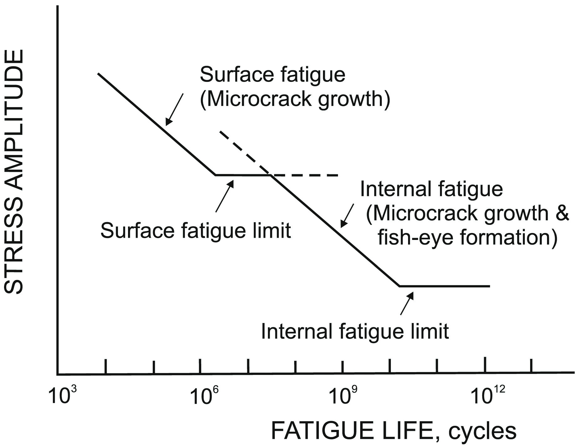
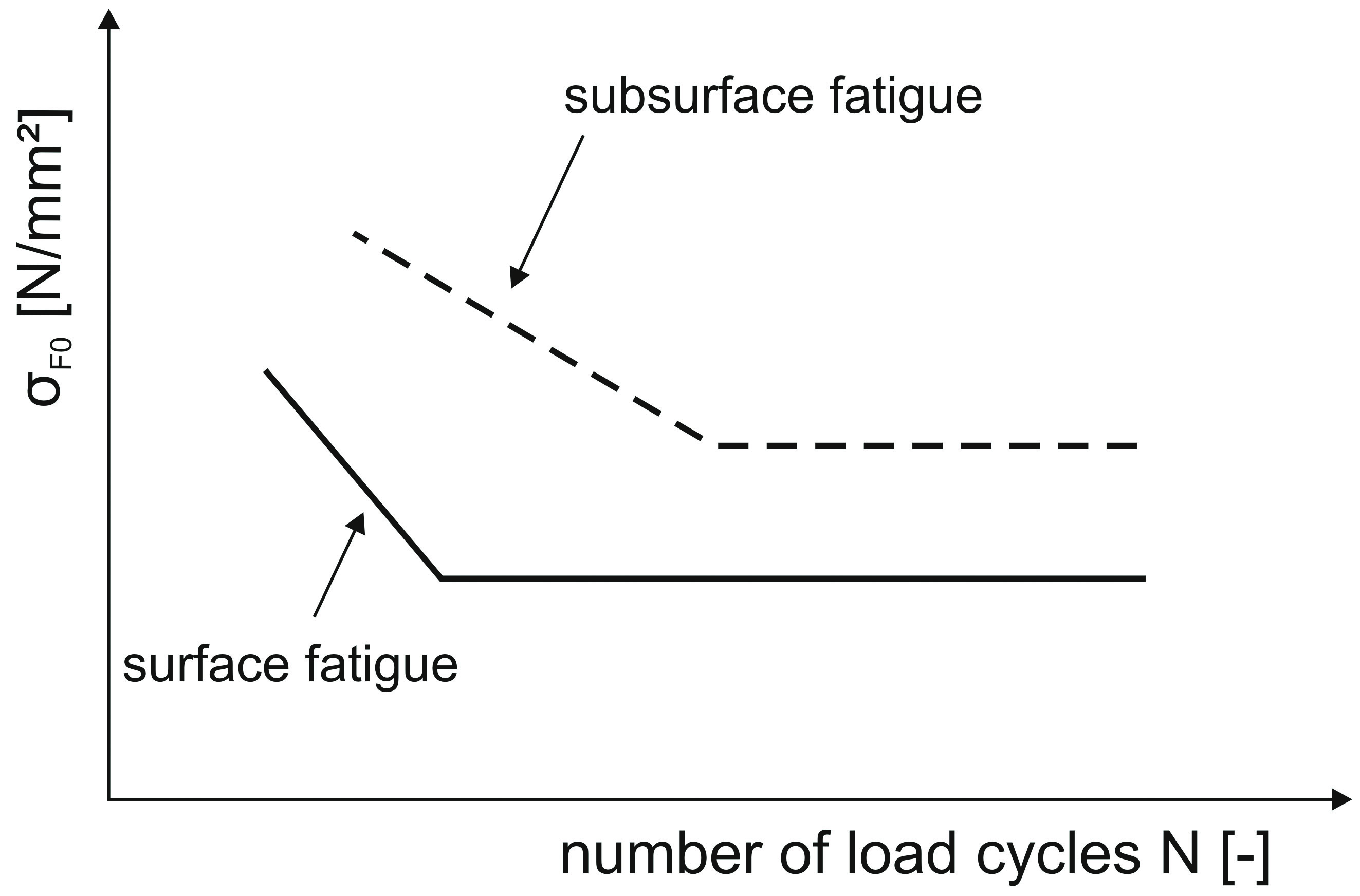
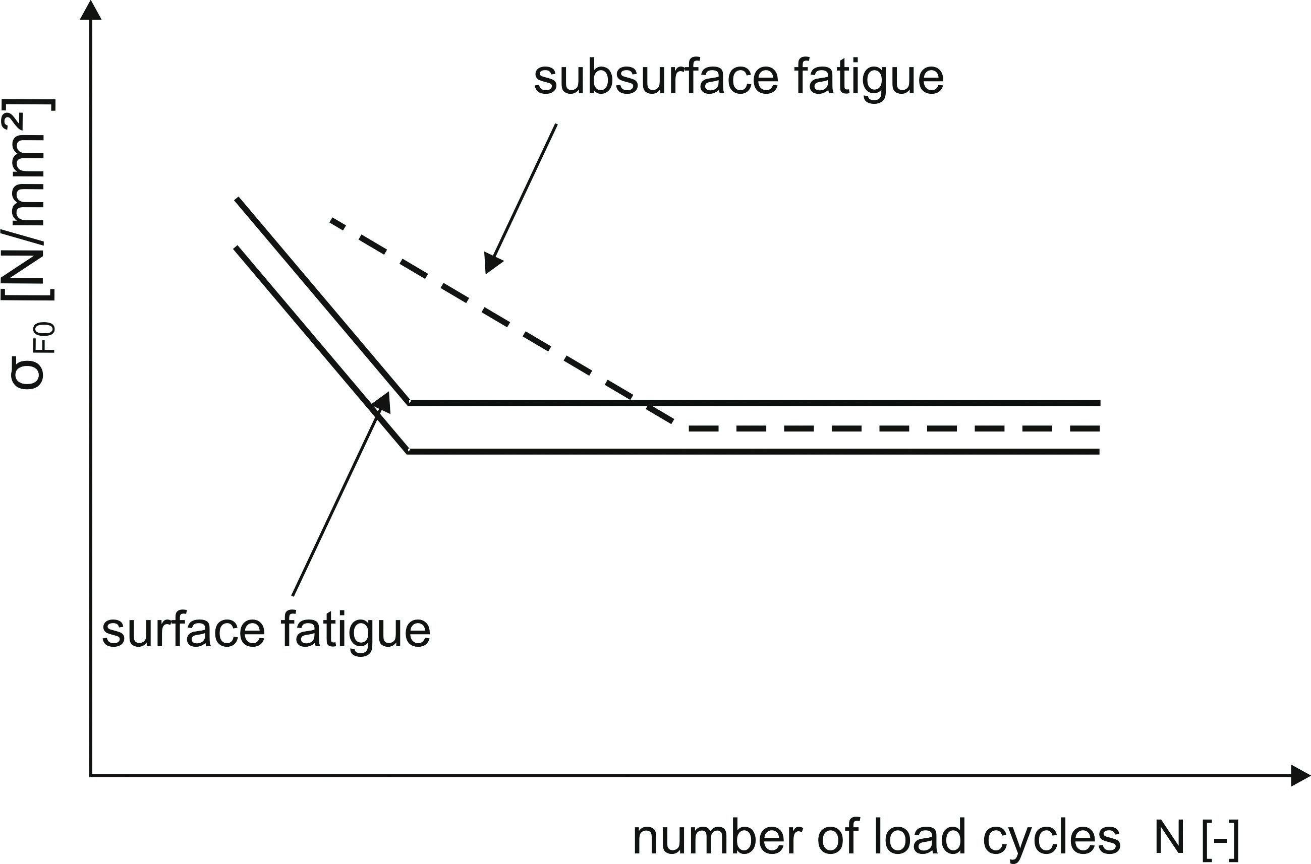
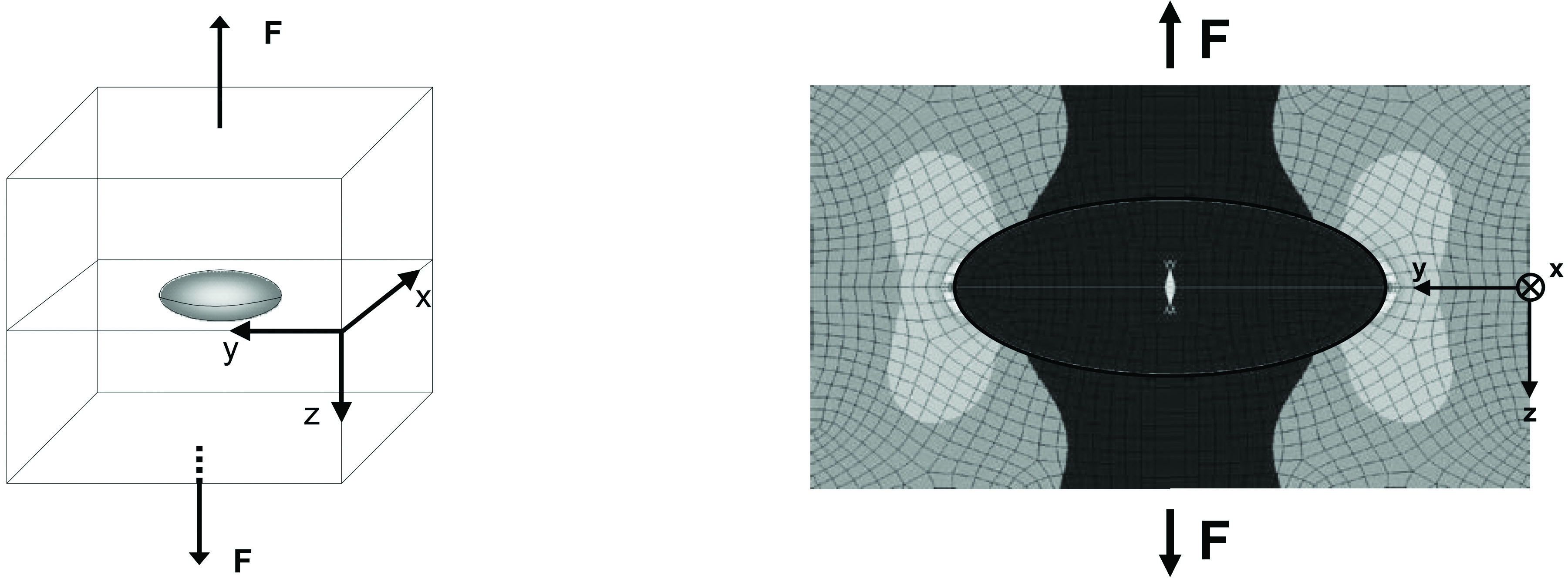
Extensive studies [8], [9] on the initiation and propagation of internal cracks in gears or simple specimens already exist. Most of them describe the same propagation process of fatigue crack initiation and essentially specify the three different areas of the fish-eye failure according to Figure 2 [9]. The inclusion in the center surrounded by the GBF (Granular Bright Facet), an area of multiple microcracks, and the surface crack, as a result of the subsurface cracks, form the typical appearance of these failures. Surface crack initiation occurs at high stress levels and relatively low numbers of load cycles, whereas subsurface crack initiation is mainly observed at lower stress levels and in the high cycle range. As a consequence, failures with a crack initiation under the surface tend to decrease the tooth root load-carrying capacity in regions of high numbers of load cycles. As a result, the normally applied S-N curve has to be converted schematically to a stepwise S-N curve (Figure 3), which takes into consideration the possible reduction in load-carrying capacity in the high cycle range.
Relating to the different gear standards, ISO 6336 [7] takes a decrease of the tooth root load-carrying capacity in high cycle areas into account. The corresponding life factor is based on AGMA 2001 [1] standard and considers various influences, such as cleanness of material, residual stresses or signs of fatigue. This factor is the result of assessments and experiences and is insufficiently secured by systematic experimental results in the high cycle range.
Influence of the Existing State of Stress in the Tooth Root
Gears are exposed to different types of stresses during their manufacture, for example from milling, heat treatment, grinding, shot peening. These stresses in the material overlap with applied stresses caused by the existing load. The different states of stress affect the load-carrying capacity of gears in different ways. To evaluate the load-carrying capacity of gears it is necessary to know the local stress situation and the associated strength of the material itself. The local load induced stresses mainly depend on the current load situation and the size of the gear, whereas the local strength of the material is primarily affected by base material, previous heat treatment, peening conditions or irregularities in the material itself (according to Figure 4).
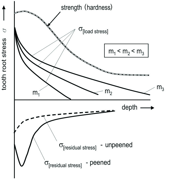
of case hardened gears depending on material depth.
Common calculation methods for tooth root bending stress, such as ISO 6336-3 [7], apply the point of contact of the 30° tangent and the tooth root fillet to maximum local tooth root bending stress. The maximum local tooth root bending stress generally occurs on the surface of the root fillet due to slip deformations, surface defects and additional notch effects.,Depending on the current state of stress, different fracture modes can be determined on gears. Experimental investigations [3] regarding high cycle fatigue on gears of various sizes, materials, and residual stress conditions showed that the main factors on high cycle fatigue of external gears are residual stresses, tooth size, and the material cleanness. These influences are regarded more closely in the following.
Residual Stresses
The state of the art in industrial practice is often a cleaning process after previous heat treatment to remove scale layers and impurities of case hardened gears with the help of blast cleaning techniques. Besides the mentioned cleaning effects, an additional increase of the tooth root load-carrying capacity caused by residual compressive stresses can be noticed. This positive stress situation on and just below the tooth root surface counteracts the tensile load stresses and leads, especially on the surface and in the near surface layer, to an increase of the local fatigue strength. Therefore, the values of the tooth root load-carrying capacity for case hardened gears, material quality MQ, published in the standard ISO 6336-5 [7], depend on gears that have been professionally blast cleaned under industrial standards. Furthermore, ISO 6336-5 [7] attributes case hardened and shot-peened gears an increase of the tooth root load-carrying capacity of 10% compared to blast cleaning.
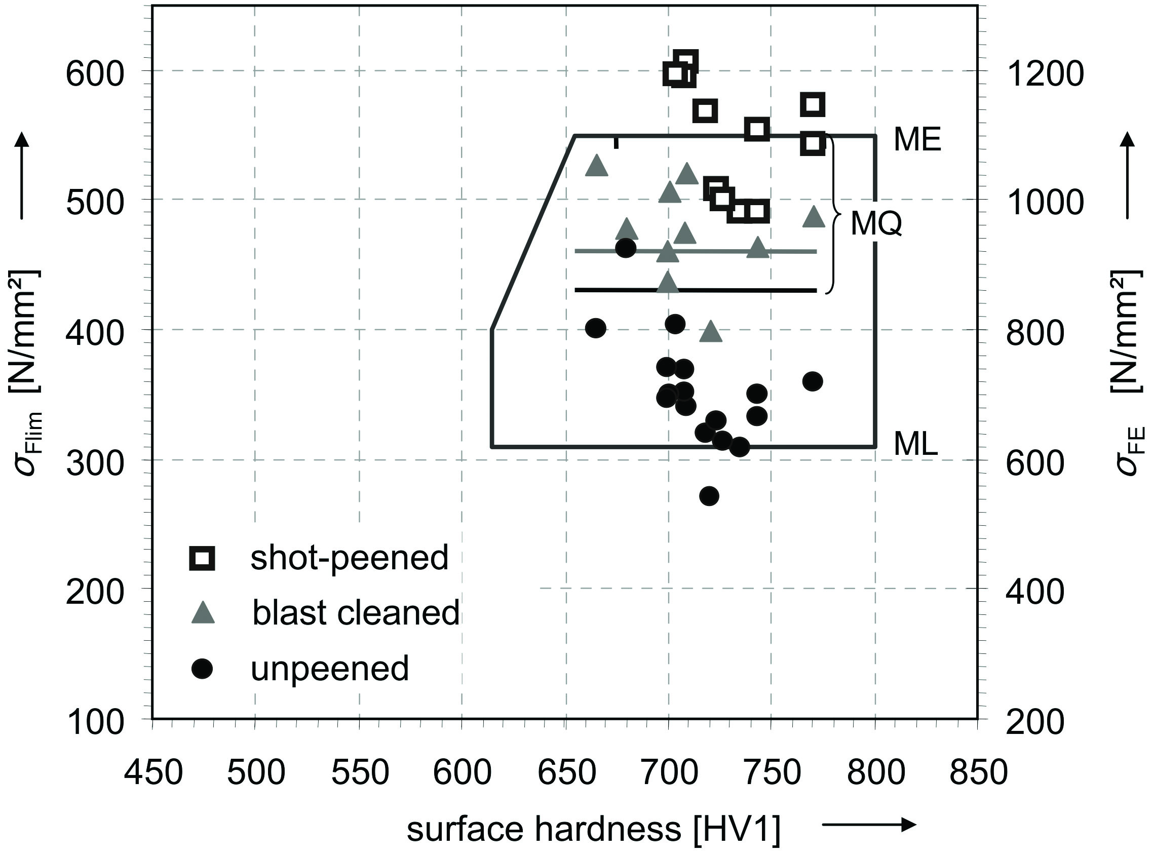
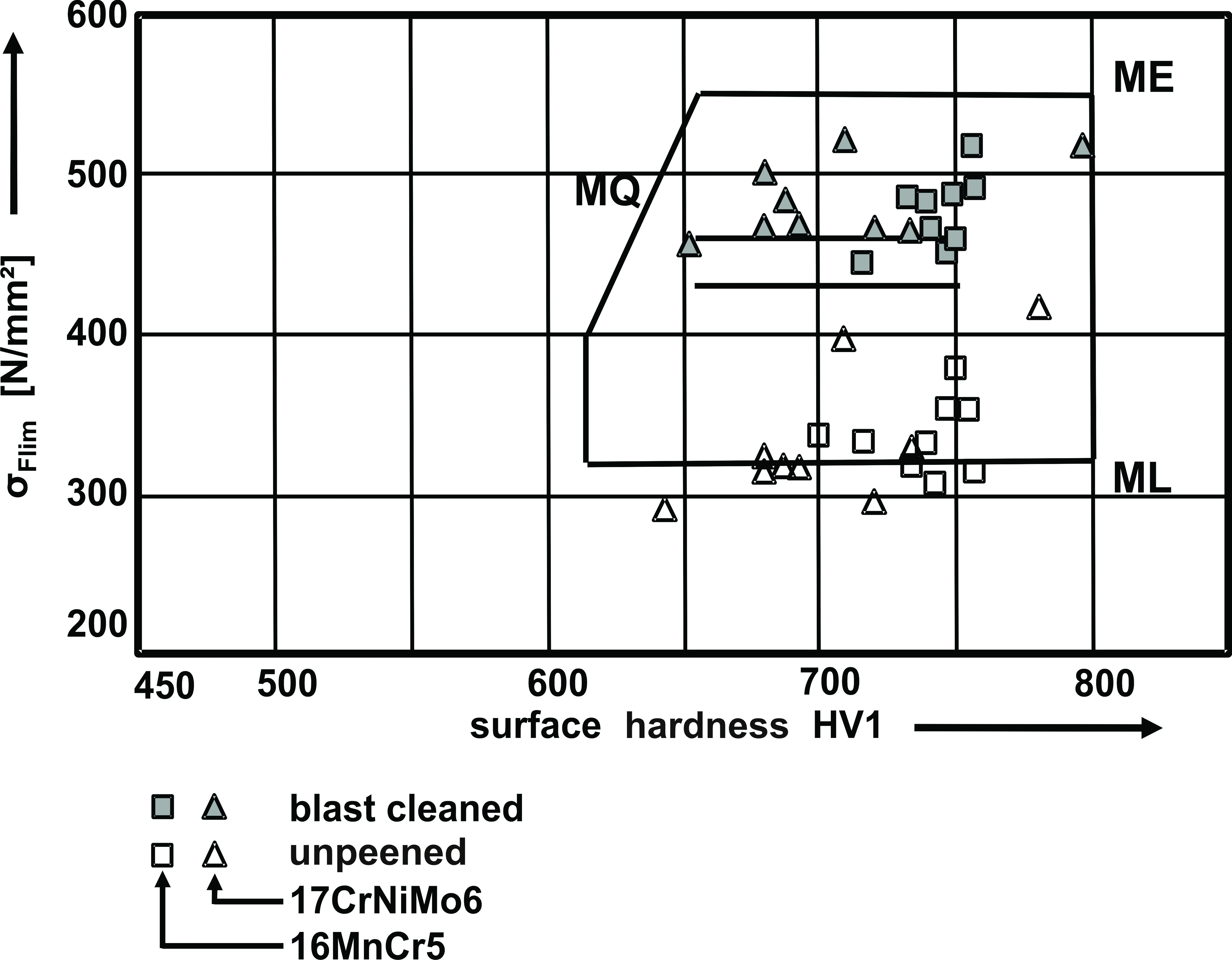
Concerning the major influence of peening in general, extensive experimental investigations in diverse studies [6], [10], [12] on gears and other components have been carried out. Figure 5 and Figure 6 contain exemplary test results of tooth root bending tests on unpeened and peened gears of different sizes and materials. The increase of tooth load-carrying capacity of peened gears can be observed. It should be noticed that these test results are based on standard tooth root bending test methods with an endurance limit of 6 · 106 load cycles.
Residual compressive stresses influence the surface and near surface layer and subside very quickly into the depth of the material. As a result the residual compressive stresses counteract the highest prevailing load stress conditions on and just below the surface, and may prevent an initiation of cracks from the surface. However, in deeper parts of the material the local residual stresses subside much more quickly than the load stresses and cannot significantly contribute to the local material strength. As a consequence, the local stress can exceed the local endurance strength of the material, especially with the presence of defects in the material, which may lead to an initiation of cracks under the surface. These cracks propagate slowly, depending on the current load, and may influence the high cycle fatigue.
Therefore one objective of this study was to investigate the fatigue behavior of case hardened gears of various sizes, materials and peening conditions. The following model representation was established based on the experimental results in order to interpret the test results in consideration of the current state of the art.
The evaluation of the experimental investigations resulted in the conclusion that each breakage, with crack initiation on and under the surface, has its own S-N curve corresponding to the respective fracture mode. The position of these two S-N curves depends mainly on the current residual stress situation and the material cleanness. Thereby residual stresses primarily influence the position of the S-N curve for surface fatigue, material cleanness the position of the S-N curve for subsurface fatigue.
Due to the experimental results of unpeened spur gears with residual compressive stresses < 400 N/mm², the S-N curve for surface fatigue is probably located below the S-N curve for subsurface fatigue (Figure 8). This means that these gears with normal material cleanness show either fracture with crack initiation on the surface or fatigue resistance. The high load stresses on the surface and in the near surface layer cannot be sufficiently counteracted by the residual compressive stresses and thus exceed the local strength of the material. Tooth root breakages with crack initiation on the surface are the result.
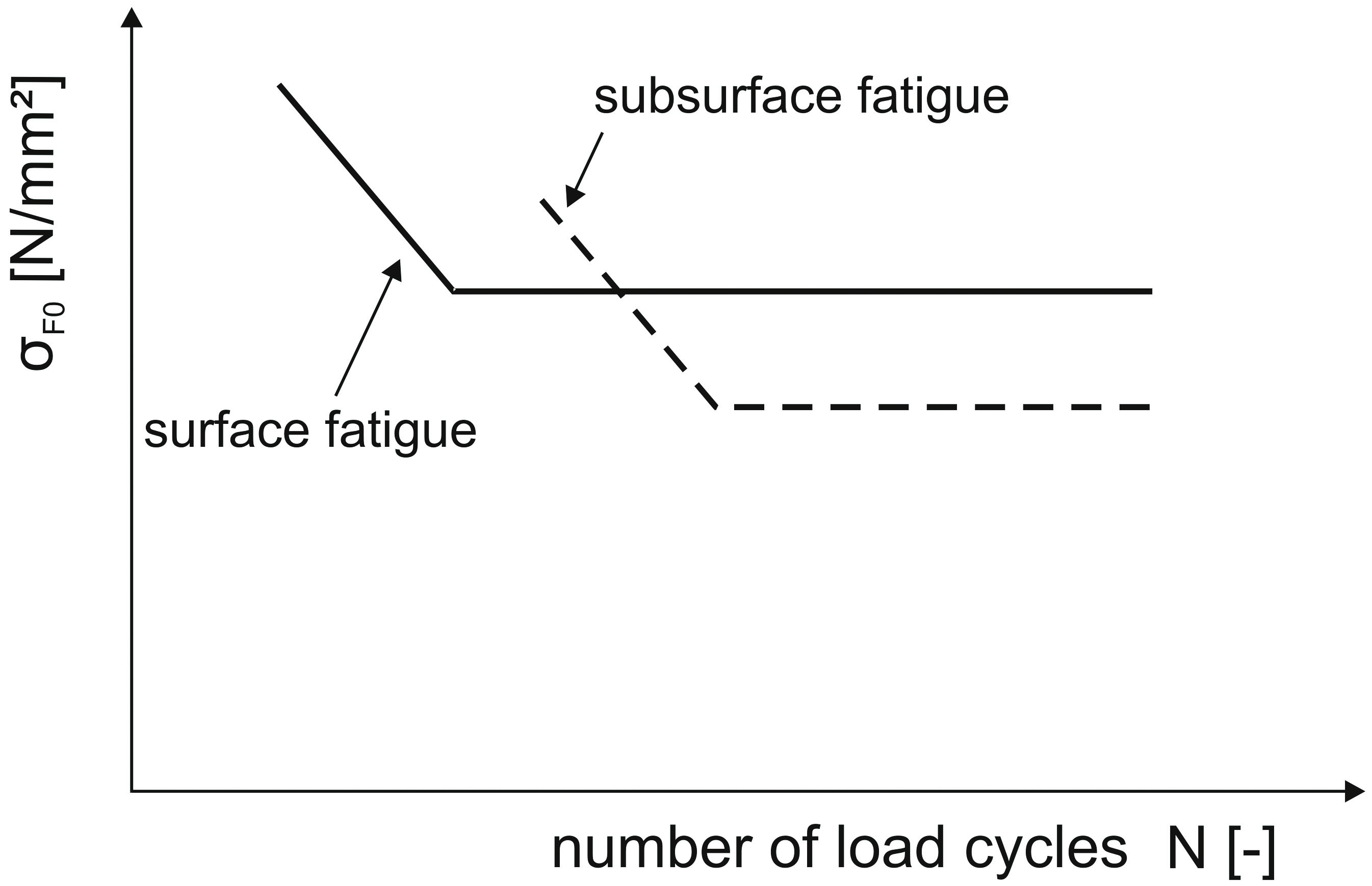
Blast cleaned gears, with typical residual compressive stresses of 400–900 N/mm², show a strengthened surface layer because of the increased residual compressive stresses. The S-N curve for surface fatigue of these gears is consequently lifted up to a higher stress level. That means that both S-N curves (surface and subsurface) can be located on a similar stress level. The S-N curve for surface fatigue in this case can be located above, below or on the same level as the S-N curve for subsurface fatigue, depending on the present cleanness of the material, the residual compressive stresses and load stresses (Figure 9). Thereby both fracture modes are possible, whereby high cycle fatigue normally will not be considerably reduced by common material cleanness.
The effect described above will even be strengthened by shot-peened gears with residual compressive stresses > 900 N/mm². Based on the induced residual stresses, the surface and the surface layer experience a further strengthening and therefore the S-N curve for surface fatigue is additionally lifted up to a higher stress level (Figure 10). The result is that the difference of the stress level between the two S-N curves varies widely, depending on the material cleanness, the residual compressive stress and the load stress.
Furthermore the appearance of tooth root breakages with crack initiation under the surface are promoted and at the same time leads to a more or less sharp decrease of the tooth root load-carrying capacity in high cycle fatigue.
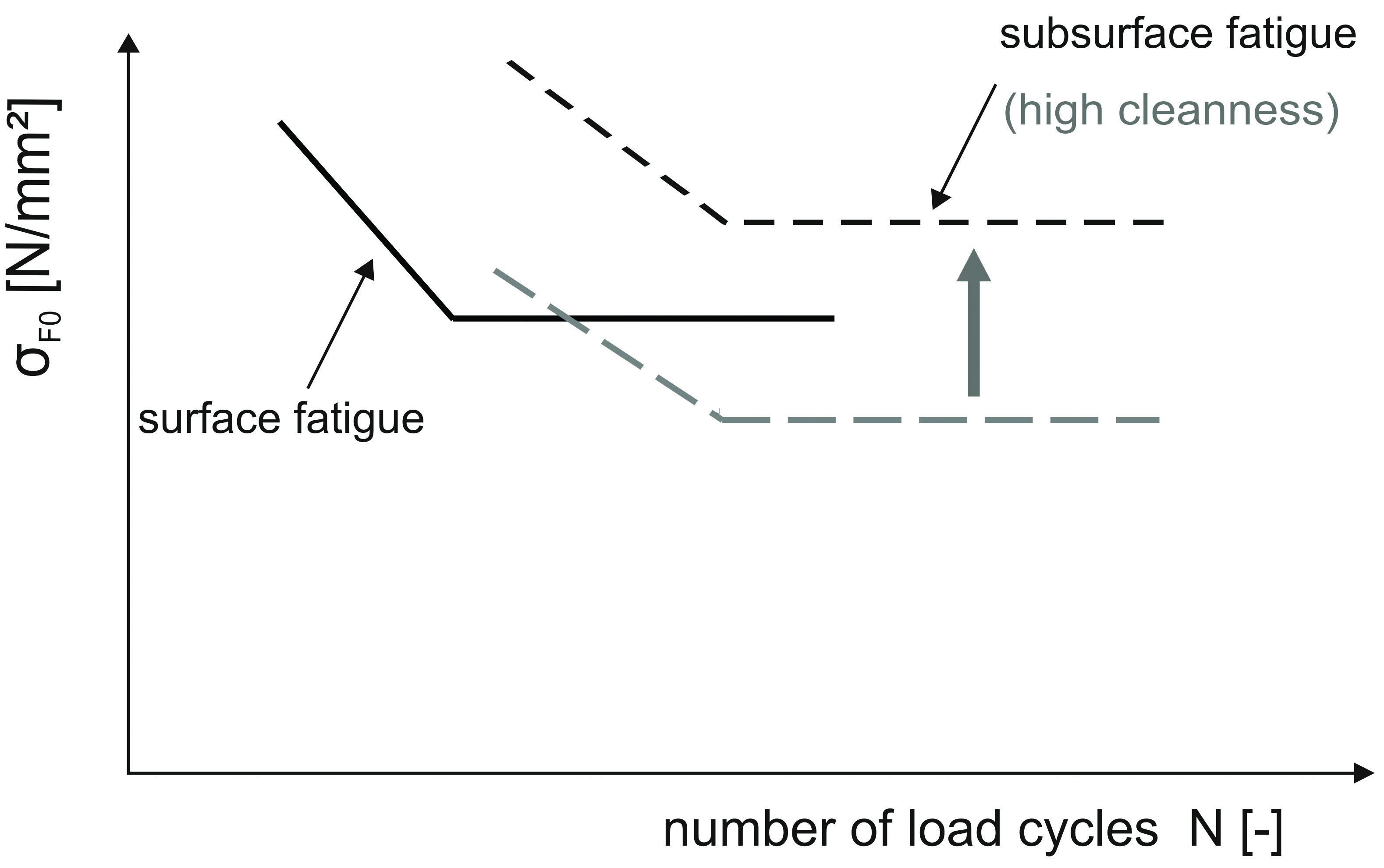
Based on the test results, shot-peened gears with a high material cleanness did not show breakages with crack initiation under the surface. Following the established model representation, the S-N curve for the internal fracture mode is lifted up to a higher stress level and breakages with crack initiation under the surface can be avoided (Figure 11). As a result, the desired increase of the tooth root load-carrying capacity can be used even at high numbers of cycles.
Tooth Size
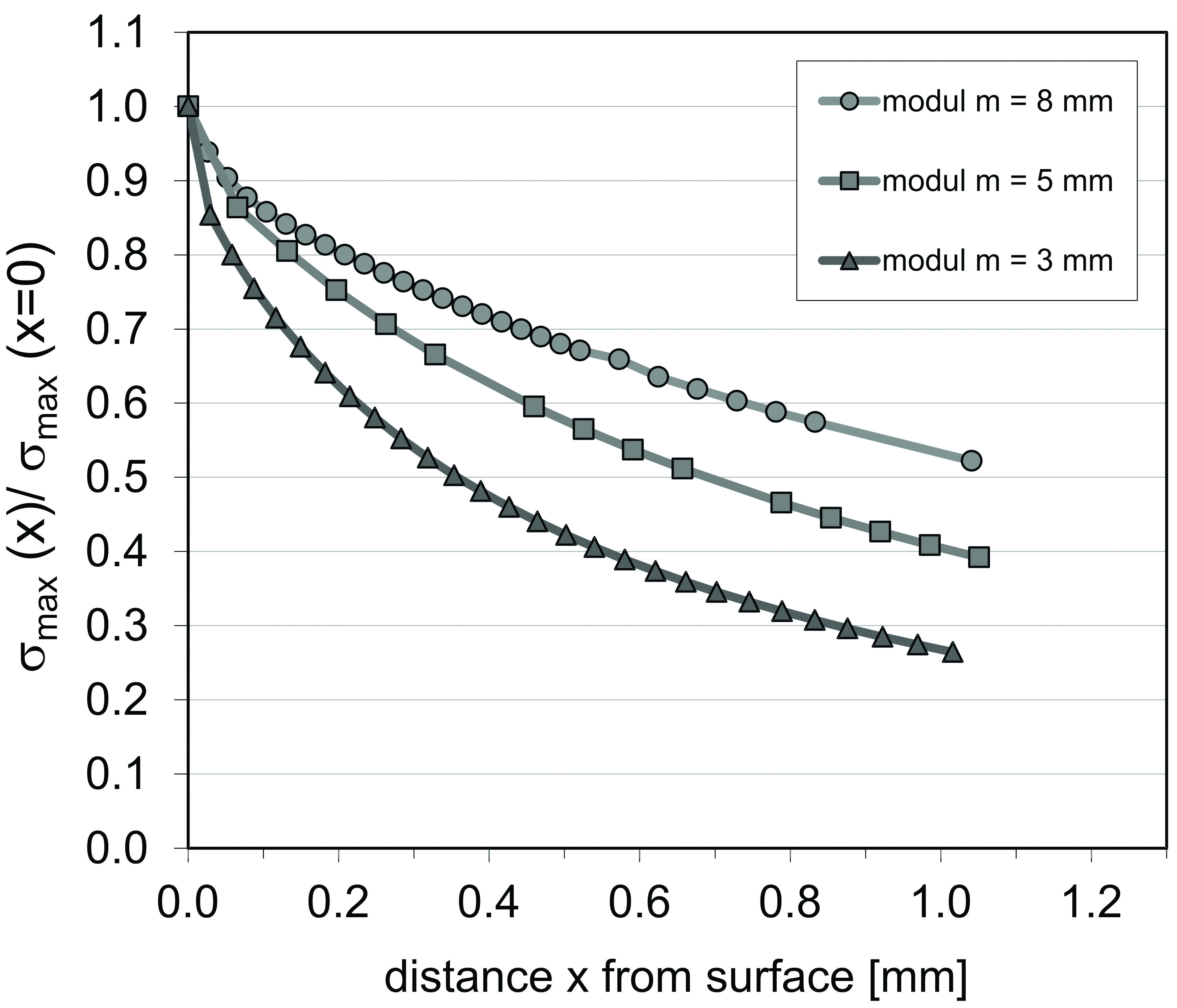
The influence of the tooth size on the fatigue strength is essentially based on the following basic reasons: statistical, geometrical and technological influences as well as the influence of stress distribution and surface condition [11]. The standard ISO 6336 [7] also takes these influences in form of a size factor into account with a decrease of tooth root load-carrying capacity on gears with a module larger than mn = 5 mm. The statistical influence takes, among other things, the presence of defects on and below the surface of the material into account. Furthermore the different stress situation on and below the surface especially affect the tooth root load-carrying capacity and the damage pattern. To determinate the local stress condition in the material depth it is important to know the load induced stresses, besides residual stresses.
Therefore, extensive theoretical investigations using FEM calculations were performed [10] by calculating the local load stress in the tooth root area and comparing the different load stresses distributions for gears of different size. Figure 12 summarizes the main results of the theoretical studies for 3 tooth size examples.
Cleanness of Material
The cleanness of the material plays an important role in tooth root load-carrying capacity. Small defects and non-metallic inclusions in the material can negatively affect the local stress condition on and below the surface. The results of FEM calculations [2] (Figure 13) show that the local load stresses lead to stress peaks at and near these inclusions in the material.
These stress peaks may exceed the local strength of the material and therefore lead to an initiation of micro cracks. These micro cracks propagate in a very slow process during sustained applied stress cycles and form an internal crack, which finally leads to tooth root breakage in the range of high numbers of cycles. Especially peened gears with a strengthened surface and near surface layer due to residual compressive stress conditions are influenced by these defects of the material. Therefore these defects essentially determine the high cycle fatigue of case hardened and peened gears. In addition to the quantity of material defects, the size of the defects themselves is important. Calculations with different defect sizes in different depths of the material show that the critical tooth root bending stress decreases with an increase of defect size and that large defects are still critical in deeper parts of the material [2], [3]. All in all it should be noticed that the less clean the material is, the greater the number and size of inclusions can be found in the material. Large defects decrease the critical local stress, which may lead to a breakage with crack initiation under the surface, if the critical local stress is exceeded. A greater number of defects, on the other hand, increase the probability of the presence of critical inclusions at critical depths of the material.
Experimental Test Results
Within a research project [2], [3], an extensive test program has been carried out on case hardened spur gears of various sizes, materials and residual stress conditions in a pulsator test rig. The main focus of the test program was the tooth root bending strength in the range of high numbers of load cycles up to 100 · 106 to estimate relevant influences on the high cycle fatigue. Table 1 contains the main geometrical data and heat treatment information of the gears tested in this investigation.
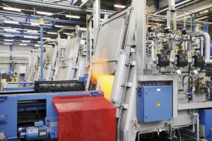
The bending tests have been consistently carried out in pulsator test rigs according to Figure 14.
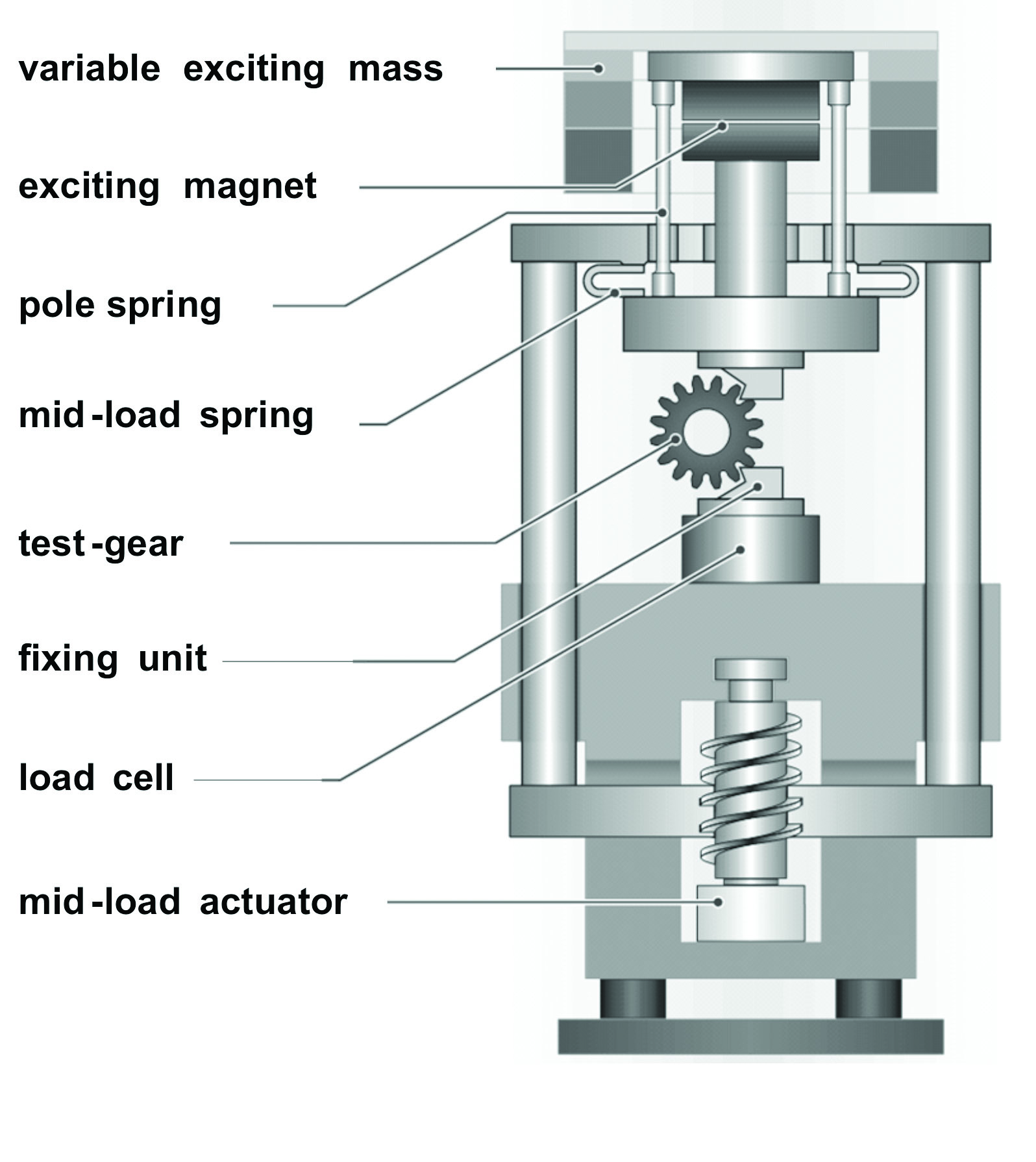
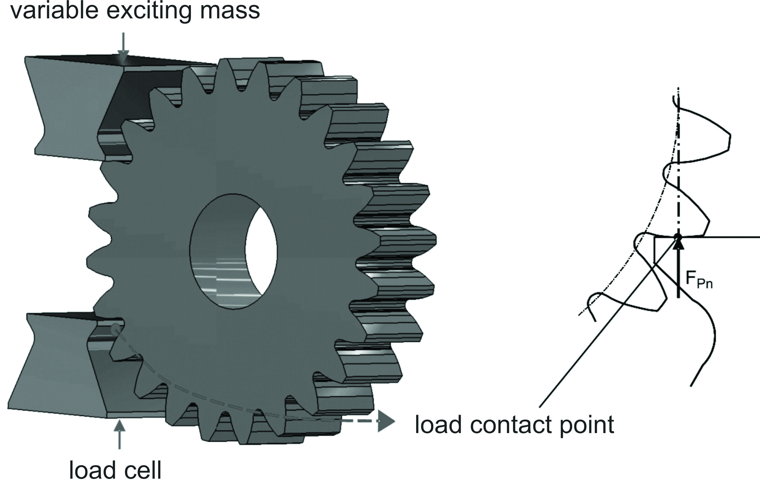
The frequency of the tests depended on the tested gear size and amounted to 50–100 Hz. The test conditions were continuously monitored and recorded by computer and oscilloscope systems. The clamping of the gears was made symmetrically between two parallel plane jaws (Figure 15). The number of clamped teeth was chosen in such a way that the force of the pulsator was set in the range of the external point of single contact. With the help of a special designed device a reproducible clamping could be ensured. The evaluation of the test results and the determination of tooth root normal bending stress were performed according to [7] or rather [5].
Besides the experimental tests in the pulsator test rig, extensive metallographic investigations, including among other things residual stress measuring, hardness distributions, microstructure assessment and material cleanness, were carried out to evaluate the pulsator test results.
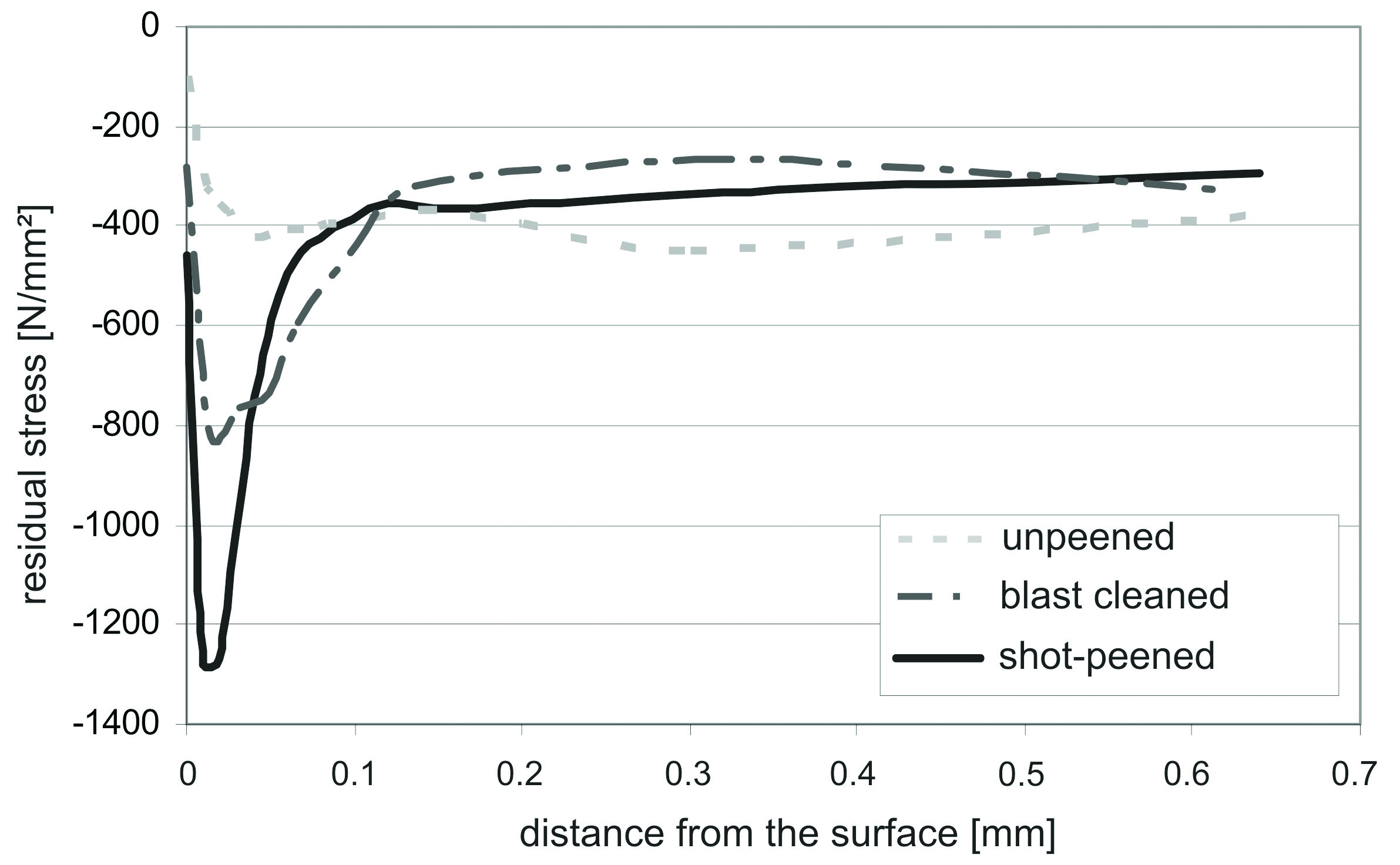
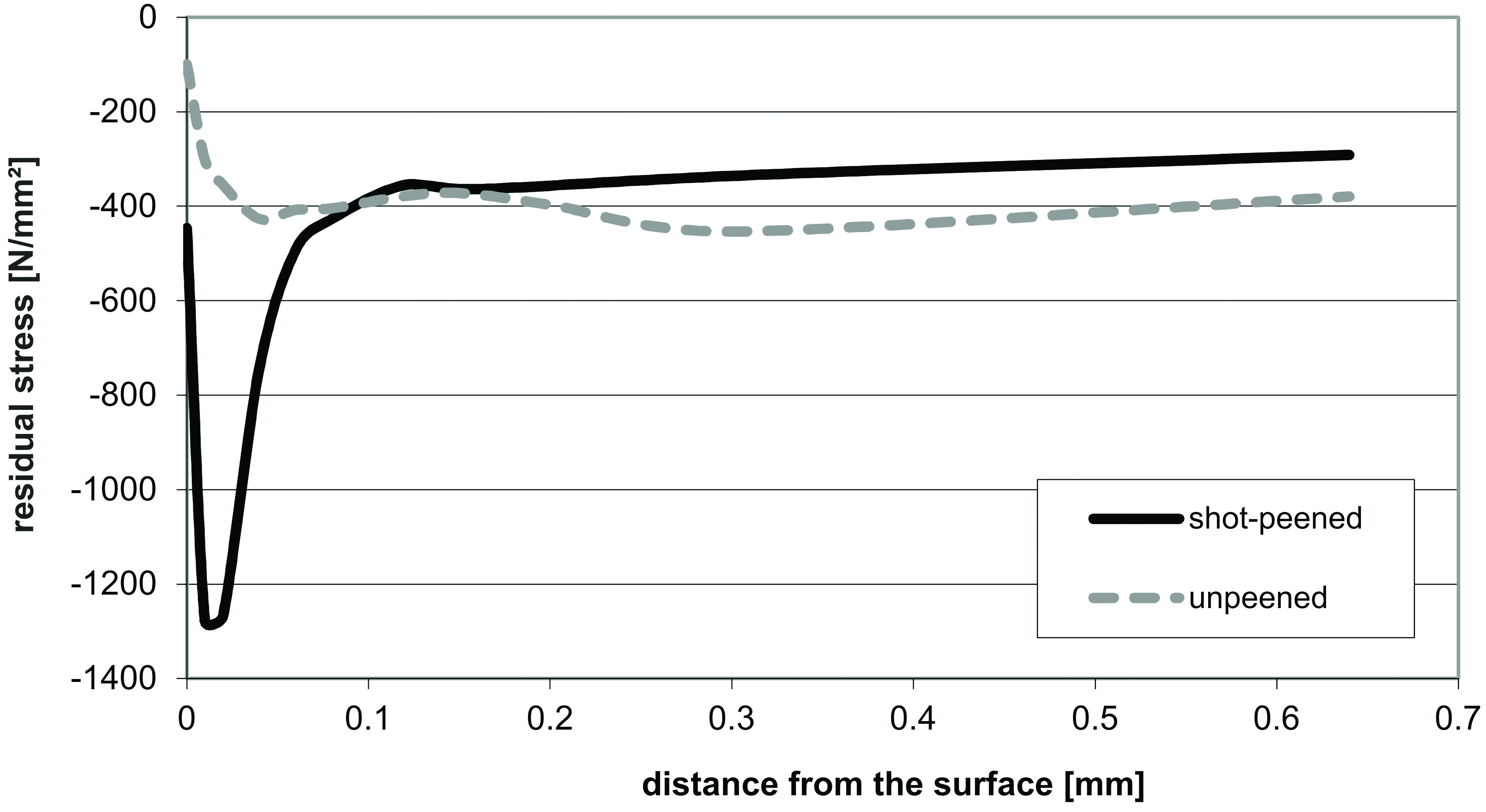
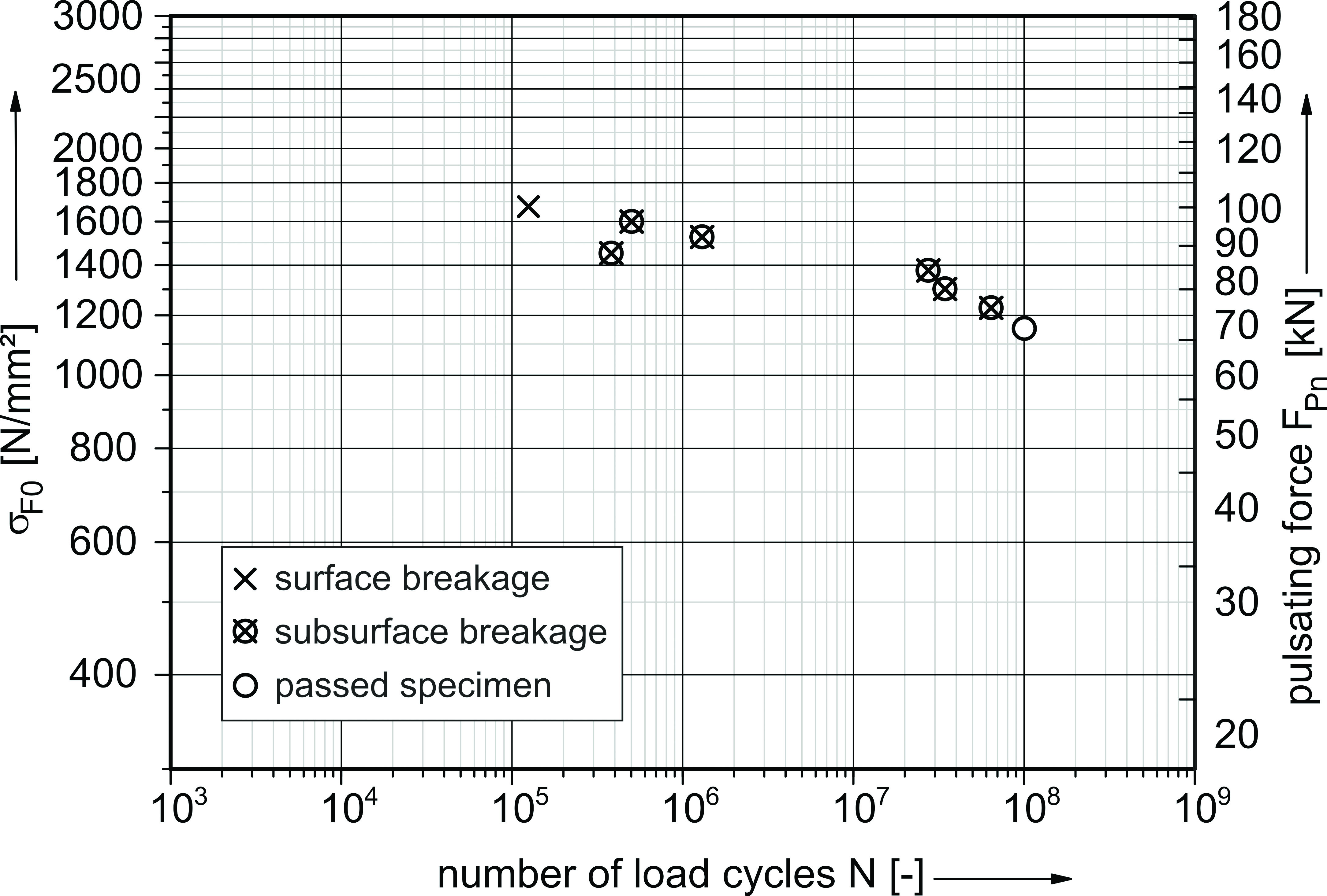
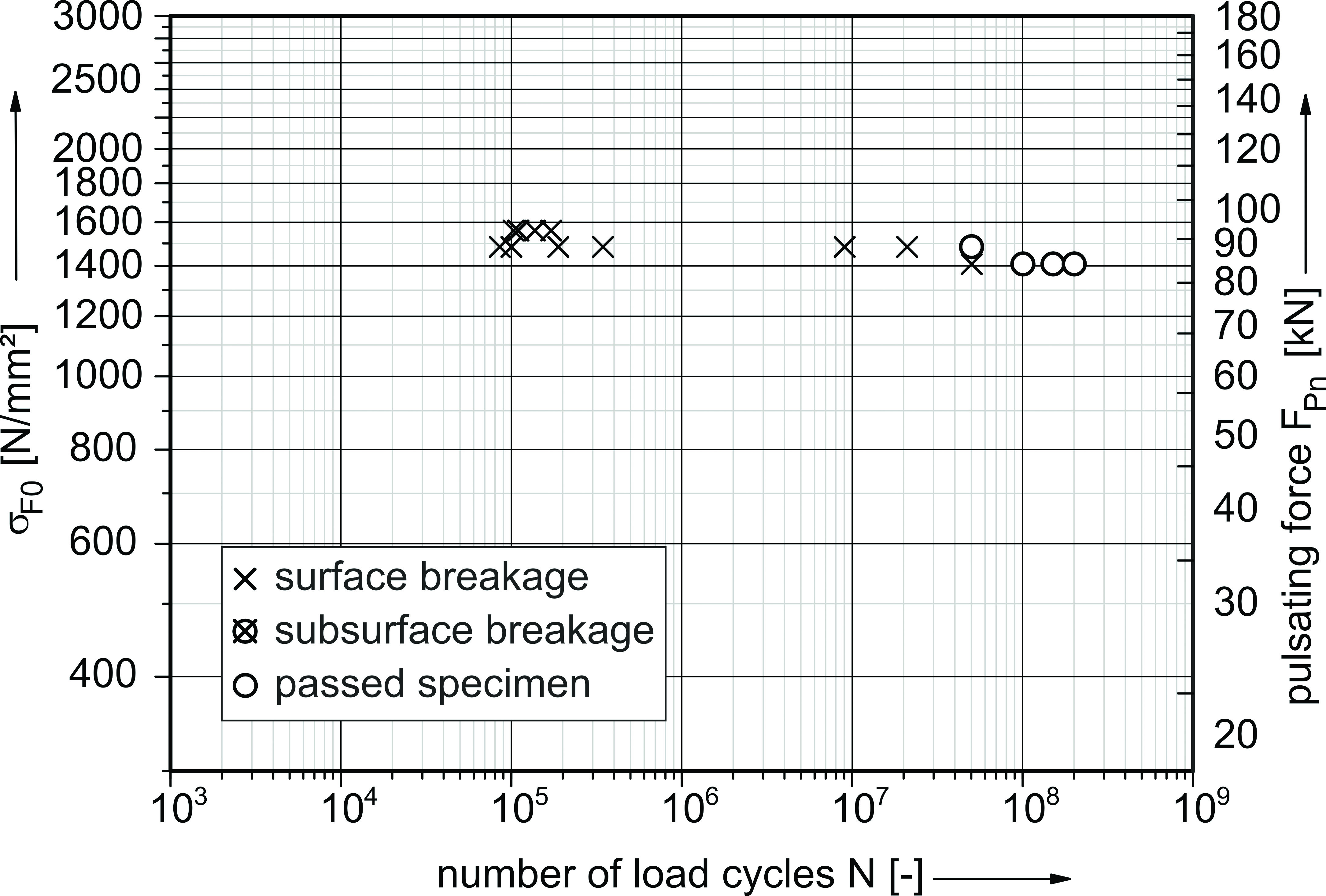
The following selected test results represent only a small amount of the experimental investigations performed. The model representation already presented is based on these test results and the presented main influences on high cycle fatigue have been derived. Figure 16 and Figure 17 contain the test results of two variants (16MnCr5 – typical case hardened steel for middle size gears) with tooth size module mn = 5 mm, with equal material cleanness (sulfide SS inclusions, size 3.9 according to [4]), in unpeened and shot-peened condition. Both test series are from one material batch and from the same heat treatment lot. Figure 18 additionally shows the associated residual compressive stress curves.
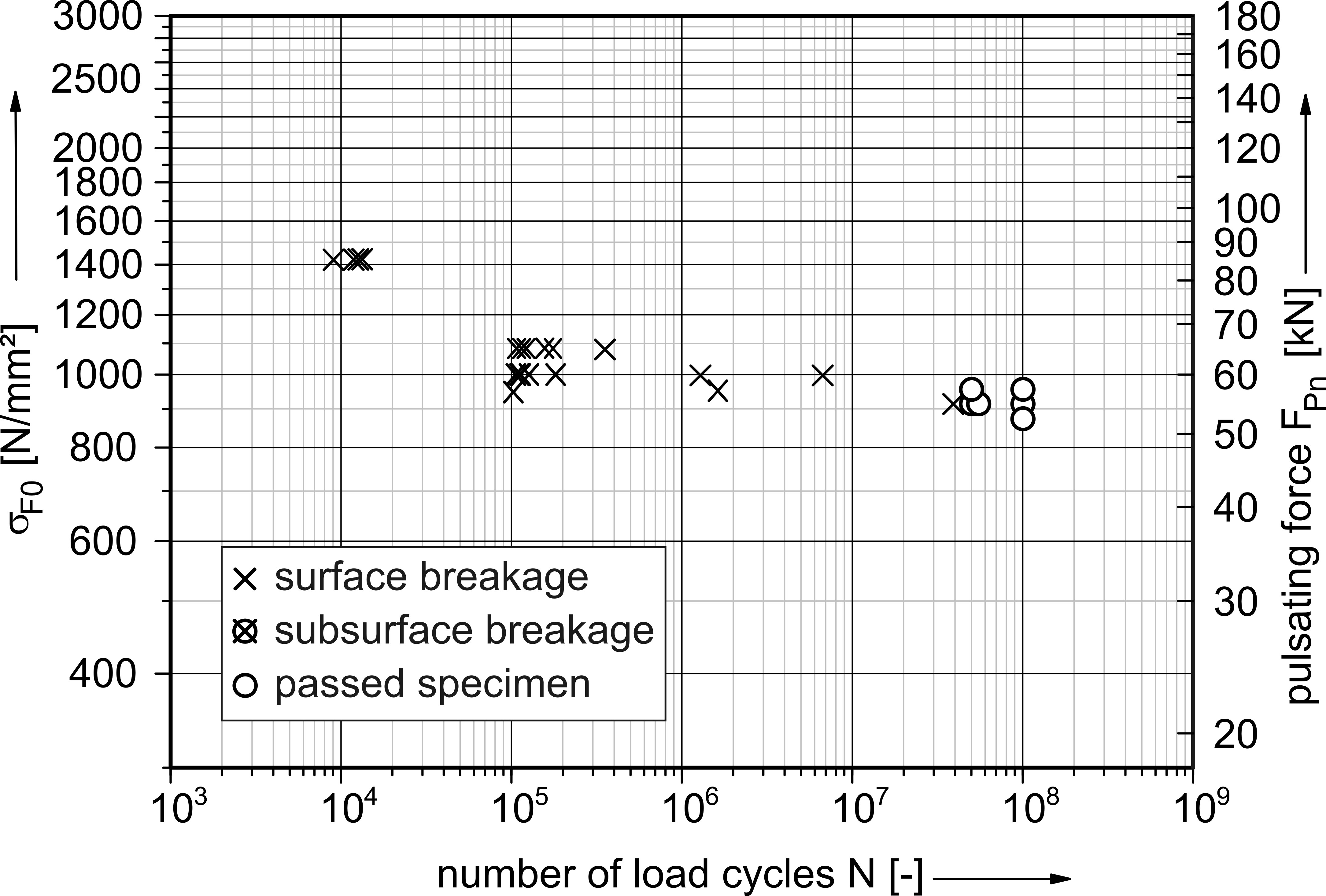
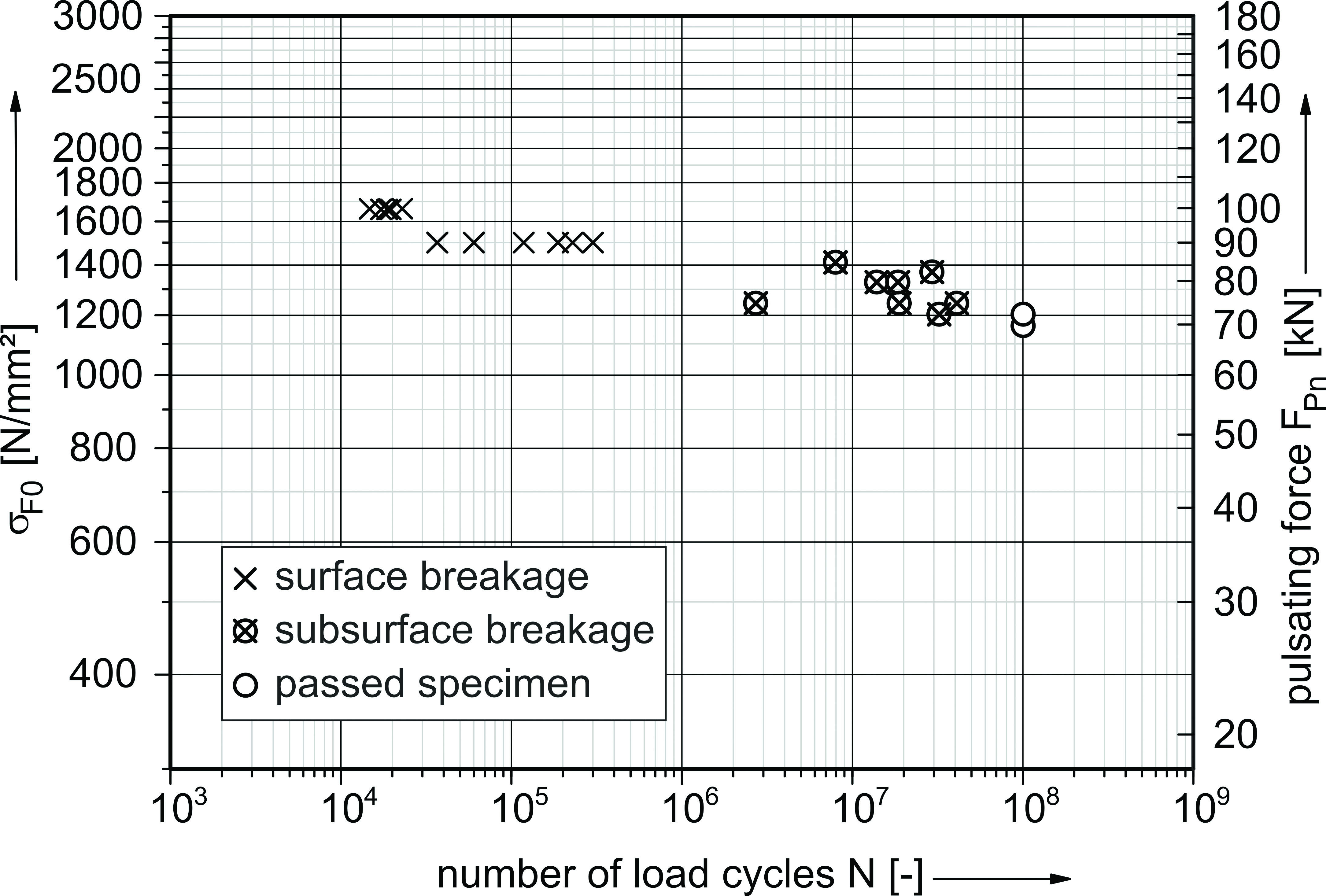
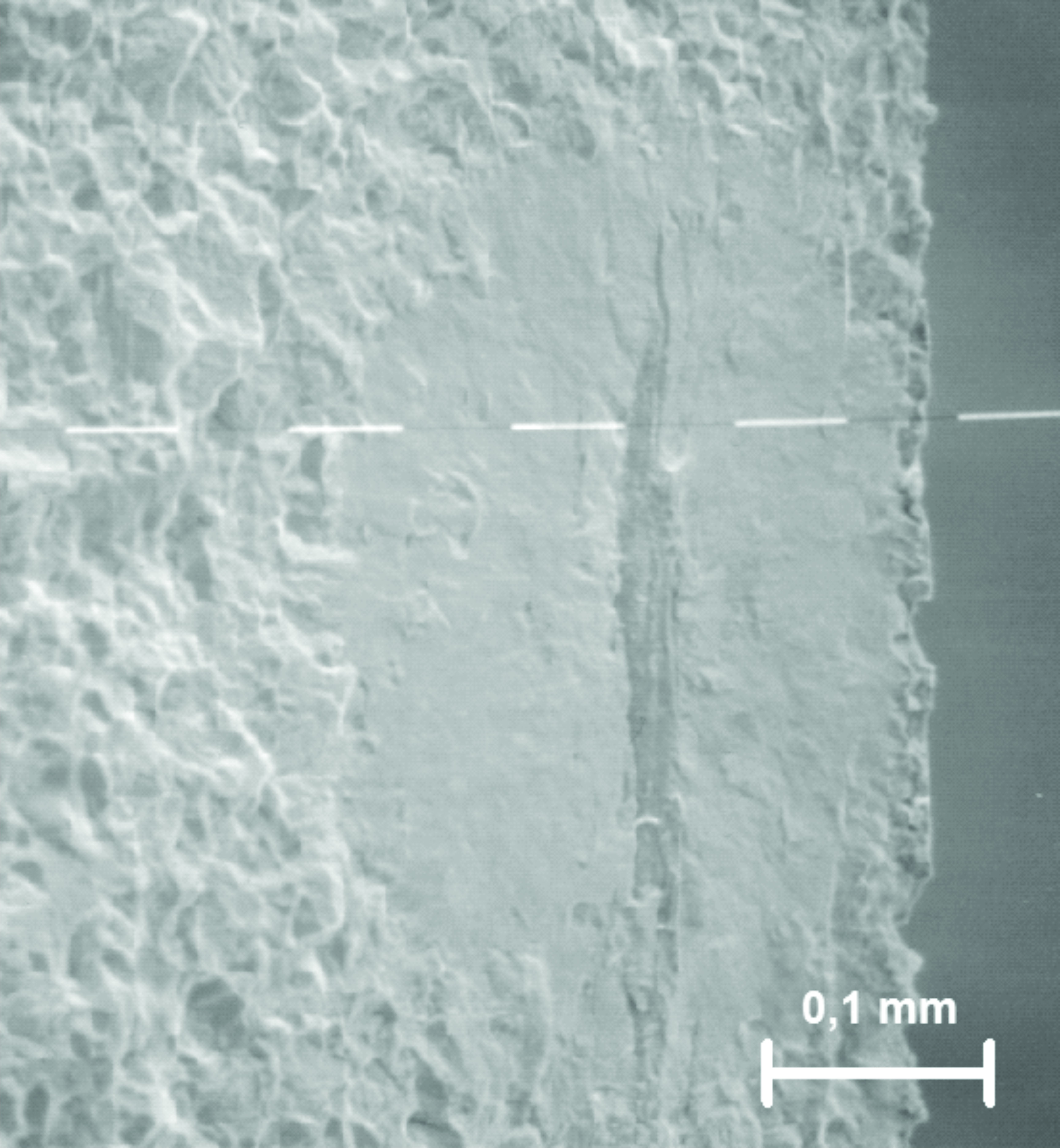
The unpeened variant shows no breakages with crack initiation under the surface. All of these tooth root breakages were due to surface cracks and are located, except for two breakages, in a usual range of load cycles. Referring to the model representation, the test results show a damage behavior according to %%0914_FZG_Fig8%%. In contrast to the unpeened variant, shot-peened variant generally shows an increase in the tooth root load-carrying capacity. Thereby, in the range of high number of load cycles, only tooth root breakages with crack initiation under the surface occurred, which mainly influenced the high cycle fatigue of this variant. These test results support the assertion of the model representation in %%0914_FZG_Fig10%%. The tooth root load-carrying capacity of the shot-peened variant is strongly influenced by these late breakages and results in a decrease of nearly 15% compared to usual cycle limits of 3-6 · 106. Nevertheless, in consideration of the subsurface fatigue in the range of high numbers of load cycles, the shot-peened variant shows an increase in the tooth root load-carrying capacity of nearly 25% compared to the unpeened variant. All breakages of the shot-peened variant have been examined with the aid of scanning electron microscopy. The detected inclusions have been analyzed concerning their chemical structure, size and location. In this the inclusions mainly involve MnS, as well as a combination of Al, Ca and Mg. The average size was 0.03 mm with an average depth of 0.16 mm in regards to the surface (CHD550HV ≈ 0.8 mm). Thus all of the examined internal cracks are located within the case hardened layer, but at a material depth with relatively low residual compressive stresses. The location of these crack initiations basically differs from typical depth location of failures known from the tooth flank. Figure 19 shows an example of a breakage with crack initiation under the surface. The typical fish-eye structure can be mentioned.
The test results demonstrate the influence of residual compressive stress, not only on the load-carrying capacity but also on the fracture mode and resultant high cycle fatigue. The assumption of a stepwise SN curve with different stress levels between the two curves and their impact on the fracture mode can be confirmed by these and other results.
Besides the influence of residual stresses, the influence of the material cleanness on the tooth root loadcarrying capacity in high cycle range was investigated. Therefore, variants of the same size (module mn = 5 mm), material (18CrNiMo7-6) and residual stress conditions (shot-peened, according to Figure 22), but different material cleanness were examined. The corresponding tooth root bending test results are illustrated in Figure 20 and Figure 21. Although the two variants are from different material batches and different heat treatment lots, the analysis of the hardness distributions and the microstructure assessment of these variants show comparable results.
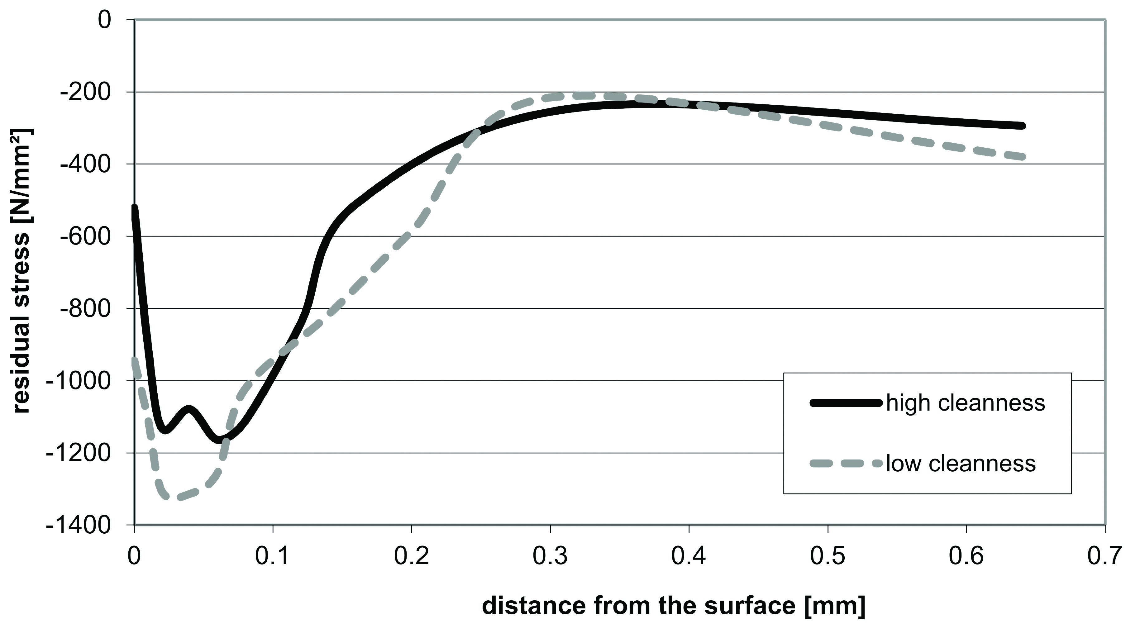
Both variants show tooth root breakages in the range of high cycle fatigue, but only the variant with low material cleanness shows breakages with crack initiation under the surface and the connected decrease of high cycle fatigue (see also model representation in Figure 10) compared to the variant with high material cleanness. The test results conclude that the variant with high cleanness does not show inclusions of critical size in the critical surface layer, which results in crack initiation under the surface because of the local stress situation. The result is that the load-carrying potential of shot peening can be used even in the range of high load cycles and subsurface fatigue seems to be avoided because of a high material cleanness (according to the model representation shown in Figure 11).
The test results show that the residual stresses and the material cleanness or rather the presence of inclusions of critical size in the material associated with the local load stresses, have a dominant and direct influence on internal fracture mode and resultant high cycle fatigue. In view of the experimental results, it becomes obvious that the initiation of internal cracks not only depends on the residual stress condition or the presence of inclusions. It seems rather to be an interaction of state of load stress, state of residual compressive stress and critical inclusions in the material.
In general, the experimental test results do not show an appreciable decrease of the tooth root load-carrying capacity with a fatigue cycle limit of 100 · 106 compared to standard methods on gears with residual compressive stresses < 900 N/mm² (typical clean blasted condition). According to this, the values of the tooth root load-carrying capacity for material quality MQ published in the standard ISO 6336-5 [7] remain valid for the examined tooth sizes and common material cleanness even for a fatigue cycle limit of 100 · 106. A further increase of the load-carrying capacity due to shot-peening can be confirmed by the achieved test results. Nevertheless, especially for case hardened, shot-peened gears, additional influences on the high cycle fatigue should be taken into account.
Summary
The tooth root load-carrying capacity is one of the determining factors in gear design. Besides the strength of the material itself, the existing state of stress (load induced stresses and residual stresses) significantly influences the tooth root load-carrying capacity, also in particular the high cycle fatigue and the related fracture mode. In order to verify the high cycle fatigue behavior of the tooth root of case hardened gears, substantial theoretical studies as well as an extensive program of tooth bending tests have been carried out on case hardened gears of various sizes, materials and residual stress conditions.
Based on the test results and the knowledge of further investigations taken from the literature, a model representation was established to interpret the influence of different local stress situations on the tooth root load-carrying capacity and different fracture modes in high cycle ranges. Therefore, the idea of a stepwise S-N curve, already known from a variety of investigations in the literature for simpler specimens [8], [9], can also be transferred to gears. The different level locations of these two S-N curves for the different fracture modes mainly depend on the current residual stress condition, as well as on the material cleanness. They describe the occurrence of tooth root breakages with crack initiation on and below the surface and the related high cycle fatigue of case hardened gears.
The experimental test results have shown the high potential regarding tooth root load-carrying capacity due to peening operations in high cycle ranges up to 100 · 106 cycles. Additionally, the experimental test results confirm the theoretical statements of the presence of a stepwise S-N curve behavior of case hardened, peened gears and the appearance of different fracture modes. Furthermore, the test results confirm the published values of the standard ISO 6336-5 [7] regarding tooth root load-carrying capacity of typically cleaned (case hardened) gears even for fatigue cycle limit up to 100 · 106 cycles. Nevertheless, especially for case hardened, shot-peened gears, additional influences on the high cycle fatigue should be taken into account.
In conclusion, the theoretical and experimental results of the research project have shown that the initiation of internal cracks and high cycle fatigue of case hardened gears not only depends on the residual stress condition or the presence of inclusions. It seems rather to be an interaction of state of load stress, state of residual compressive stress and critical inclusions in the material.
Acknowledgements
This research project was sponsored by the Forschungsvereinigung der Arbeitsgemeinschaft der Eisen und Metall verarbeitenden Industrie e.V. (AVIF) with an equity ratio of the Forschungsvereinigung Antriebstechnik (FVA).
References
- ANSI/AGMA 2001-C95: Fundamental Rating Factors and Calculation Methods for Involute Spur and Helical Gear Teeth. AGMA, Alexandria, 1994.
- Bretl, N.: Einflüsse auf die Zahnfußtragfähigkeit einsatzgehärteter Zahnräder im Bereich hoher Lastspielzahlen. Dissertation, TU München, 2010.
- Bretl, N.: Späte Zahnfußbrüche – Zahnfußbruch mit Rissausgang unterhalb der Oberfläche an einsatzgehärteten Zahnrädern. Forschungsheft Nr. 851, Forschungsvereinigung Antriebstechnik e.V., Frankfurt, 2008.
- DIN 50602: Mikroskopische Prüfung von Edelstählen auf nichtmetallische Einschlüsse mit Bildreihen. Beuth Verlag, Berlin, 1985.
- FVA-Merkblatt Nr. 0/5 – Ergänzung: Empfehlungen zur Vereinheitlichung von Pulsatorversuchen zur Zahnfußtragfähigkeit von vergüteten und gehärteten Zahnrädern. Forschungsvereinigung Antriebstechnik e.V., Frankfurt, 2009.
- Hirsch, T.: Kugelstrahlen. Untersuchungen zur Zahnfußfestigkeit kugelgestrahlter Zahnräder. Forschungsheft Nr. 126, Forschungsvereinigung Antriebstechnik e.V., Frankfurt, 1983.
- ISO 6336: Calculation of load capacity of spur and helical gears. 2006.
- Nishijima, S.; Kanazawa K.: Stepwise S-N curve and fish-eye failure in gigacycle fatigue. Fatigue & Fracture of Engineering Materials & Structures, Volume 22, Issue 7, S. 601-607, 1999.
- Shiozawa, K.; Lu, L.: Effect of Non-Metallic Inclusion Size and Residual Stresses on Gigacycle Fatigue Properties in High Strength Steel. Advanced Materials Research, Volumes 44-46, S. 33-42, 2008.
- Stenico, A.: Werkstoffmechanische Untersuchungen zur Zahnfußtragfähigkeit einsatzgehärteter Zahnräder. Dissertation, TU München, 2007.
- Steutzger, M.; Suchandt, T.; Stahl, K.: Größeneinfluss auf die Zahnfußtragfähigkeit. Forschungsheft Nr. 529, Forschungsvereinigung Antriebstechnik e.V., Frankfurt, 1997.
- Weigand, U.: Werkstoff- und Wärmebehandlungseinflüsse auf die Zahnfußtragfähigkeit. Dissertation, TU München, 1999.


 general practice for CQI-9 and AMS2750E")


