







Carburizing-quenching is a thermochemical surface treatment designed to harden the surface of steels and make them more resistant to friction, wear, and corrosion. It involves the diffusion of carbon atoms at high temperature, followed by rapid cooling to induce a phase transformation from austenite to martensite. This process therefore combines a diffusion process, possibly assisted by stress fields, a heat transfer process, and metallurgical transformations, which interact and induce residual stresses, linked to various deformations connected to the coupled processes involved.
The objective of this work is to develop a finite element model to capture these residual stresses, together with composition gradients in the material. This model, based on the Abaqus finite element software, relies on numerous user subroutines, allowing the highly coupled resolution of the physics associated with carburizing-quenching. This model is applied to a simple structure inspired by previous works in the literature, the results highlight that mechanical fields have a significant influence on both diffusion and residual stress profiles, particularly near the surface. Neglecting these effects can lead to substantial errors in the prediction of local composition and mechanical performance.
1 Introduction
Carburizing followed by quenching is one of the oldest heat treatments used to harden surfaces. This process is particularly effective in producing steels with wear-resistant surfaces, capable of enduring high stresses, deformations, fatigue, and corrosion. This improvement in surface performance is beneficial for various machine parts such as gears and bearings, used in a wide range of sectors including automotive and aerospace [1].
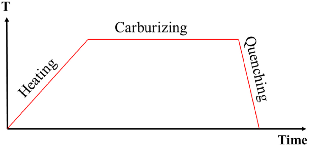
The carburizing-quenching process takes place in three successive steps (see Figure 1), which can be repeated. The first step is the heating of the part in a carburizing furnace [3] until it reaches a uniform temperature and a homogeneous austenitic state. The second step is the diffusion of carbon atoms from the surface, which creates a concentration gradient. The third and final step is quenching. This stage involves rapid cooling of the carburized part to obtain a martensitic microstructure, which plays a major role in the final mechanical properties. Martensite exhibits high strength and hardness [4], and the martensitic transformation generates residual compressive stresses at the surface, which are beneficial to the mechanical properties. However, tensile stresses are also present within the sample volume [5], which must be controlled carefully.
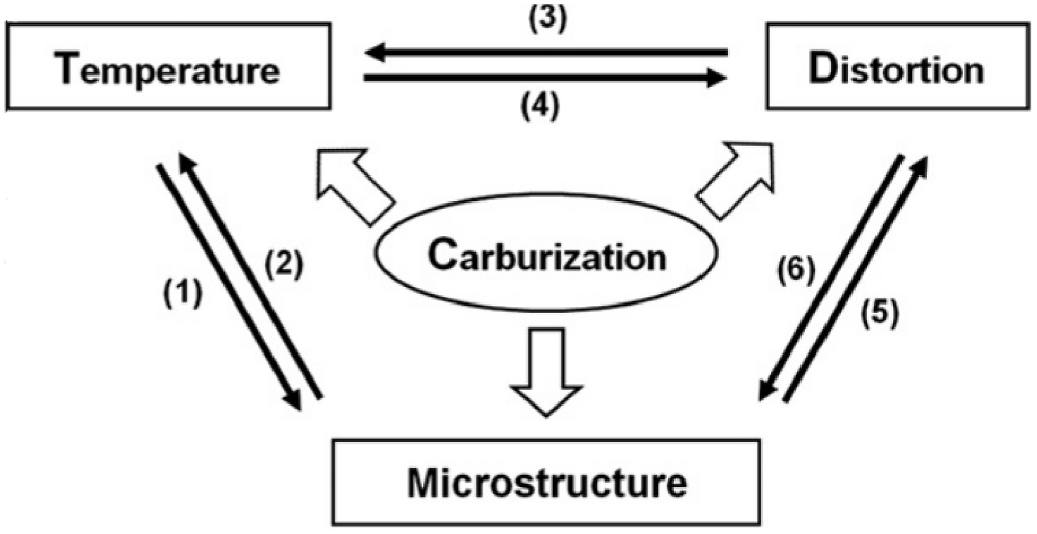
The coupling between the mechanisms involved appears at different levels (see Figure 2): The diffusion process drives the carbon-concentration profile; phase transformations are driven by temperature evolution and carbon-concentration; temperature fields are influenced by phase transformation; thermal stresses affect the mechanical response. Lastly, phase transformations are associated to transformation strains that can generate transformation plasticity [6]. Stresses can influence the kinetics of the martensitic transformation.
Many studies have been conducted in the literature, using Finite Element (FE) tools, to investigate the impact of carburizing and heat treatments on material properties (e.g., hardness, composition …); a broad (although not exhaustive) survey was carried out and summarized in the Appendix (see original article link), highlighting the relevance of the developments presented in the current study. This leads to the combination of several problems, especially related to species diffusion, heat transfer, plasticity, and phase transformation. The classical scenario consists in two stages:
- Carburizing: Species diffusion at a given elevated temperature, assumed to be constant throughout the process.
- Quenching, along with phase transformations and plasticity.
In step 2, as temperature variations are fast (especially with respect to species diffusion), no diffusion occurs.
The carbon diffusion is based on the Fick law, with a carbon diffusion coefficient D, which can be considered as carbon-concentration independent [8, 9, 10, 11, 12] or not [13, 14, 15, 16, 17]. The impact of stress and strain distribution on diffusion is usually neglected [18].
Heat transfer is usually modeled based on the Fourier’s law, in which dissipation heat sources (related to plasticity and phase change) can be considered [5,19,20], as well as thermal expansion.
During quenching, the mechanical behavior combines several contributions: elastoplasticity, transformation plasticity, and transformation strains [12,13]. The impact of viscosity on the mechanical response [21, 22, 23], or the contribution of dilatational strain induced by carbon atoms [8] can also be included. It is worth noting that a mechanical resolution is not required if the impact of internal stresses on the quenching mechanisms is neglected [15, 16, 17].
Last, phase transformations are usually described using phenomenological approaches, assuming an instantaneous process (i.e., faster than all other phenomena), depending on temperature, carbon-concentration, and stress levels [24,25]. Recent investigations proposed a kinetic model of theses transformations [8,23].
The aim of this work is to model the entire carburizing-hardening process in order to evaluate the chemical composition and internal stresses at the end of the process. This involves especially to be able to couple transient diffusion of carbon and heat (accounting for mechanical fields or not), then to link concentration, temperature and phase change, which will be considered as instantaneous.
The article is organized as follows: The used models are first presented, as well as the implementation strategy in the commercial FE software Abaqus. Then, an application is carried out on a cylinder loaded following a scenario from the literature [8], in order to evaluate the distribution of the various physical fields in the structure at the end of the carburizing-quenching process. In this work, two additional contributions are considered compared to most existing models: (i) the influence of hydrostatic stress on carbon diffusion [18,28], and (ii) the volumetric deformation induced by carbon atoms [8]. These effects, never considered simultaneously in the literature, are expected to have an impact on the prediction of residual stress distributions and carbon concentration profiles. Unless specified otherwise, all concentrations are expressed in weight percent (wt.%).
2. Modeling
The coupled problem described in Figure 2 has been implemented in Abaqus software [26] using several User Subroutines [27]. The different models considered are first presented, followed by a description of the implementation process. The phase transformation kinetics is neglected here, and only two phases are considered: austenite and martensite.
2.1 Heat transfer
The classical Heat transfer equation has been used [28], such that the temperature gradient T is linked to the heat flux ϕ in Equation 1:
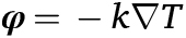
where k is the material’s thermal conductivity, leading to the following heat transfer equation (Equation 2):

ρ and Cp represent the density and the specific heat, respectively, and T˙ denotes the time derivative of T.
The temperature variation induces an isotropic dilatational strain eT, such that in Equation 3:
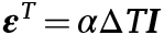
in which α is the material’s thermal expansion coefficient. ΔT is the difference between the current and the initial temperature, and eT the identity second order tensor.
No heat dissipation is considered, as it is assumed that its impact on the thermal field is negligible.
2.2 Transport of carbon atoms
Carbon atoms transport is modeled using the Fick’s first law [3,6], in which the particle’s flux J is a function of both carbon-concentration C and hydrostatic pressure gradient PH [29] in Equation 4:
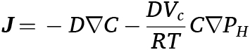
where Vc is the partial carbon molar volume, D the diffusion coefficient, R the perfect gas constant. PH = –/3trσ is the hydrostatic pressure, σ being the stress tensor. The diffusion coefficient D is modeled by an Arrhenius function [30] in Equation 5:
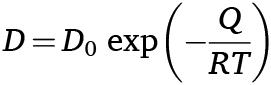
Q is the activation energy and D0 is the pre-exponential factor. Both are assumed to be composition-dependent such that [31] in Equation 6:

with concentrations in mass percent. Based on mass conservation, the temporal evolution of C can be deduced in Equation 7:
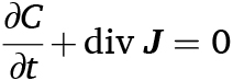
In addition, the diffusion of carbon atoms generates an isotropic dilatational strain εC, such that [8] in Equation 8:

in which αC is the volume’s expansion coefficient due to carbon diffusion and C0 the initial carbon concentration.
2.3 Phase transformation
To model the instantaneous martensite transformation, the martensite volume fraction γM is expressed using the Koistinen-Marburger law [32] in Equation 9:

where γai is the initial volume fraction of austenite, AM is a dimensionless material parameter [7] such that in Equation 10:

MS is the temperature at which martensitic transformation begins, defined by [4] in Equation 11:

2.4 Mechanical behavior
The total strain rate e˙ is assumed to be divided into several terms (small strain assumption) in Equation 12:

ε˙e and ε˙p are the elastic and plastic strain rates, respectively. ε˙T corresponds to the thermal expansion (Equation 3), and ε˙C to the dilatation induced by the presence of carbon atoms (Equation 8). ε˙tr, the transformation strain rate, corresponds to a volumetric change strain induced by the formation of martensite from austenite: since martensite has a lower lattice parameter than austenite [33], the martensitic transformation results in a relative increase in volume. Last, ε˙pt is the transformation plasticity strain rate, i.e., the plasticity due to phase transformation.
The elastic strain εe is related to the stress field by the Hooke’s law in Equation 13:
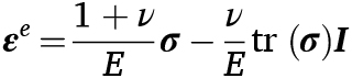
where E and v are the Young’s modulus and the Poisson’s ratio, respectively. Plastic strain is computed based on J2-flow theory, using a yield function F such that in Equation 14:

σvM is the von Mises stress, σ0 the initial yield stress and R(p) the isotropic hardening term, expressed as R(p) = k.pn . p is the cumulated plastic strain, k the hardening coefficient, and n the strain-hardening exponent (respectively set as 500 MPa and 0.5). Plastic strain rate can be computed based on the normality rule [34] in Equation 15:
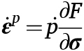
The transformation strain rate ε˙tr can be expressed as follows [5] in Equation 16:
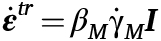
where βM is the coefficient describing the expansion induced by the structural modifications [19] and γM the martensite volume fraction (Equation 9). Last, transformation plasticity strain rate ε˙pt is given by [35] in Equation 17:
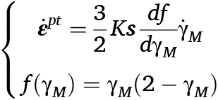
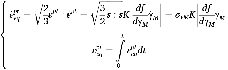
where K is the material-dependent transformation coefficient, s is the deviatoric stress tensor and f(γM) is a function describing the progression of the transformation. An equivalent transformation plasticity strain εpteq can be introduced such that in Equation 18:
2.5 Implementation
To solve the coupled chemo-thermo-mechanical problem, the Finite Element software Abaqus is used, together with several User Subroutines [27]. The “coupled-temp” displacement procedure has been used, with the degree of freedom (dof) 11 for the carbon-concentration C.
To add all the specific features presented in the previous sections, the following User Subroutine were used, either from previous developments or specifically designed for that work:
- UMATHT: Definition of the pressure-dependent particle flux [36].
- UMAT: Thermo-elastoplastic mechanical behavior (isotropic hardening) and computation of PH [36]. This subroutine has been modified to account for εpt, using the algorithm presented in [34].
- UEL: Multi-diffusion problem [37], and especially, transient heat transfer [38].
- UEXPAN: Thermal expansion [38] as well as εtr and eC.
- USDFLD: Computation of γM as a function of C and T.
The flowchart is presented in Figure 3. From the implementation strategy, all material parameters can be dependent on temperature, carbon-concentration, and martensite/austenite fraction.
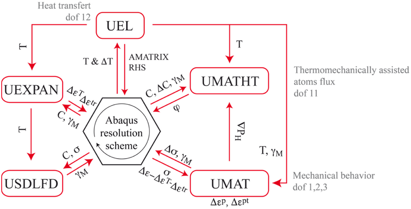
It is worth noting that the chosen implementation strategy allows the resolution of all problems simultaneously, except the phase transformation. As underlined previously, in the specific context of carburizing-quenching, this specificity is not mandatory.
3 Application
The model presented in the previous section has been applied on a reference configuration extracted from literature [8], for the sake of illustration, noting that in the current study, only purely martensitic quenching is considered.
First, the geometry and boundary conditions are presented, then the material properties, and last, results are given and commented. Two sets of computation are performed, considering, or not, the effect of hydrostatic pressure on carbon transport.

3.1 Configuration
The configuration is a cylindrical sample made of 8620RH steel (see its composition in Table 1), depicted on Figure 4a, loaded on all outer surfaces by both temperature and gaseous carbon-concentration.
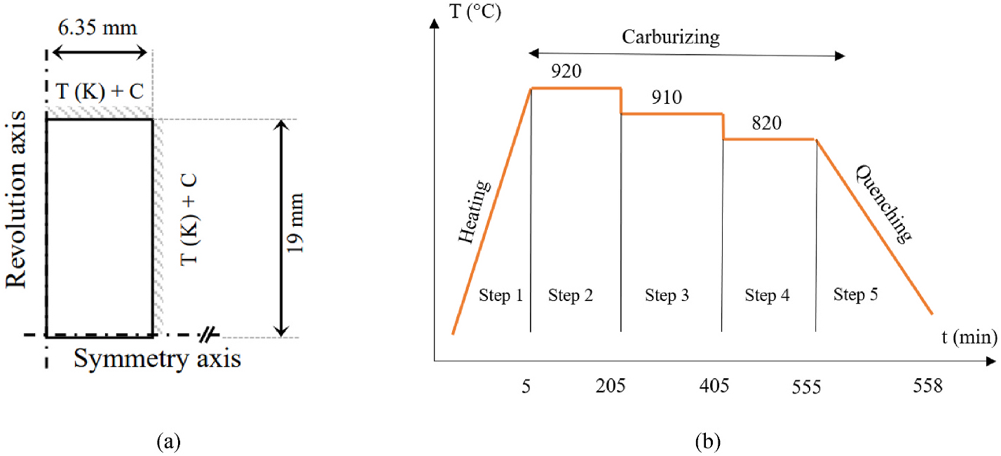
The loading scenario is divided into five steps:
- Heating from 25°C to 920°C during 5 min.
- Carburizing at T = 920°C during 200 min under a 0.9 wt% C atmosphere.
- Carburizing at T = 910°C during 200 min under a 0.85 wt % C atmosphere.
- Carburizing at T = 820°C during 150 min under a 0.75 wt % C atmosphere.
- Air quenching to 25°C during 3 minutes.
The problem is modeled in 3D (due to the way PH is computed – see [36] for further details), meshed by full integration linear hexahedral elements C3D8T. A refined mesh was used near the surface and along the symmetry axis in order to better capture stress and strain gradients. In these regions, the element size was reduced to 6 ↔ 10–3 mm. In the rest of the domain, especially toward the revolution axis, the element size was progressively increased up to 1.5 ↔ 10–2 mm.
Initially, γM = O everywhere in the sample (i.e., γAi = 1).
3.2 Material parameters
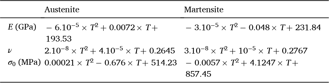
Temperature-dependent mechanical parameters were extracted from [35] for pure martensite and austenite, and fitted by polynomial functions (see Table 2).
Heat-transfer parameters (thermal conductivity k, density ρ and specific heat Cp) are provided in Table 3, from data extracted from [20]. As it was difficult to identify a polynomial function to fit these data satisfactorily, they have been used in a tabular way. It is worth noting that the evolution of the heat transfer parameters with T are not monotonic.
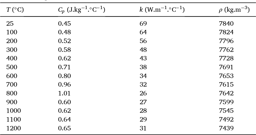
This is due to the metallurgical transformation occurring at about 800°C from BCC ferrite to FCC austenite. Thermal expansion for the martensitic an austenitic structure, volume, and phase transformation coefficients have been obtained from [8] in Equation 19:
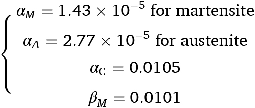
For non-pure phases, all parameters are computed based on the percentage of each phase: e.g., α = γMαM + (1 – γM)αA.
αC (Equation 19) has been identified from the results provided in [8], in which the dilatation of the sample’s diameter Δd/d is provided as a function of the temperature and the carbon content of the surrounding atmosphere.
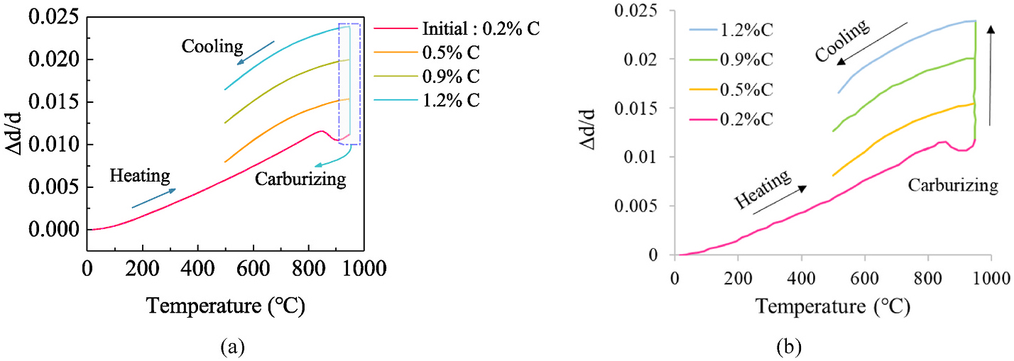
In Figure 5, the Δd/d evolution from [8] and in the present study are compared, based on the inverse identification of αC: as it can be observed, results are consistent with [8]. It is worth noting that, as temperature decreases to the ambient temperature (e.g., during step 5), the thermal strain becomes negligible compared to the dilatation induced by carbon atoms.
Equation 6 and Table 1 have been used to compute the diffusion coefficient D as a function of the carbon concertation C. The partial carbon molar volume Vc is set to 3.9 ↔ 10–6 m3/mol [18]. The transformation plasticity coefficient K is set to 2.5 ↔ 10–5 [35]. Last, the temperature Ms at which martensitic transformation begins and the material parameter AM are computed using Equations 10 and 11.
3.3 Results
A carburizing-quenching computation was performed without considering the impact of hydrostatic pressure on diffusion (Vc = 0, see Equation 4), the results of which are then discussed.
Then, hydrostatic pressure is accounted for in diffusion (Vc ≠ 0), which also has an impact on the boundary conditions.
Unless stated, all results are plotted at the end of the quenching process (step 5), along the symmetry axis.
3.3.1 Carburizing steps
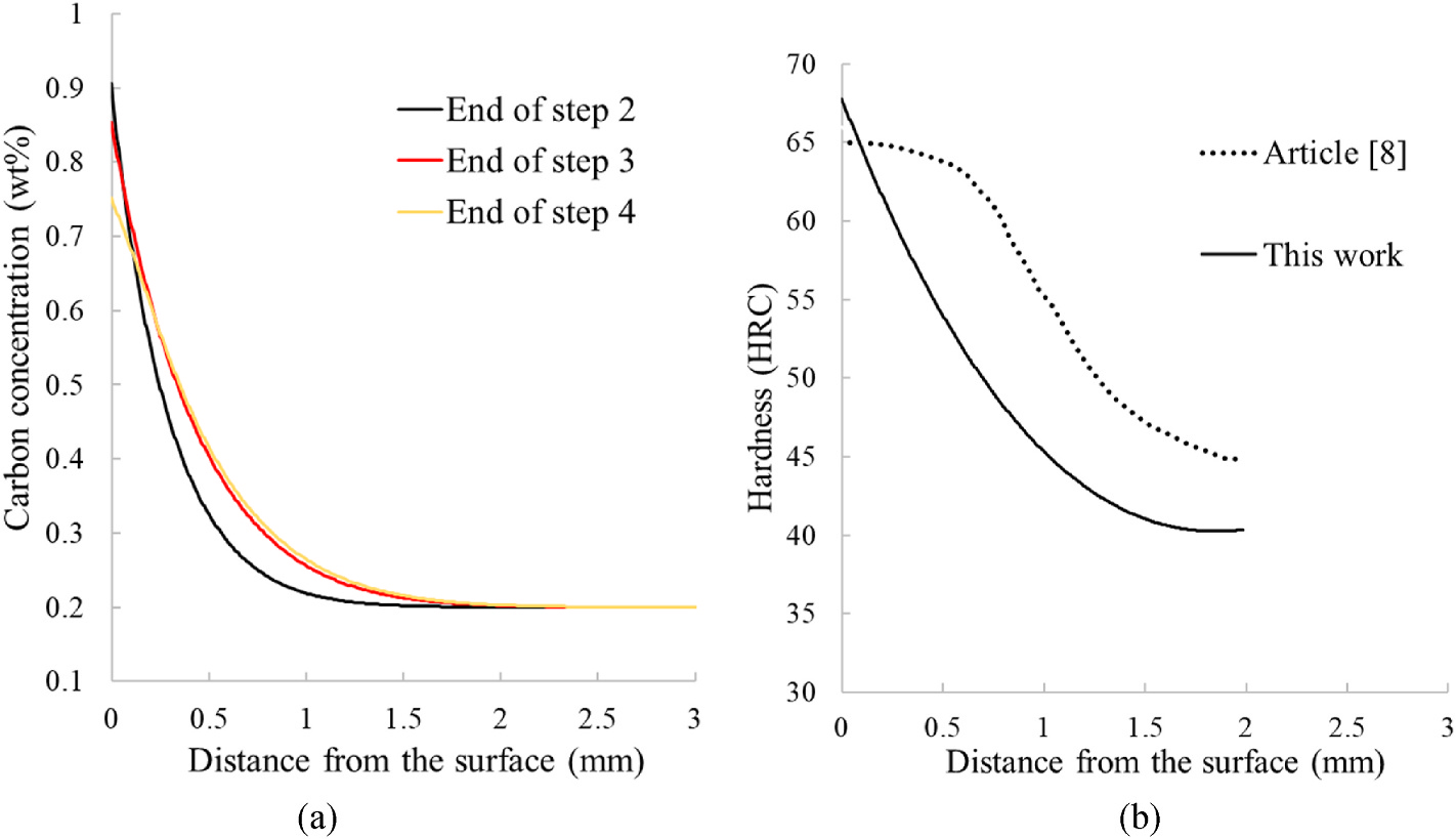
Figure 6a shows the diffusion profile at the end of each step under a carbon-rich atmosphere (steps 2–4).
It can be observed that carbon remains at the sample’s surface (less than 1 mm deep for a radius equal to 6.35 mm), consistent with the low value of D at 900°C. Step 4 shows no evolution of the diffusion profile, as the diffusion coefficient at 820°C is too low (equal to 9.29 ↔ 10–7 mm2/s when C is equal to 0.9 wt%). From these carbon profiles, the Vickers hardness HV can be estimated using the following relationship [8] in Equation 20:

where VM is a critical cooling rate for martensite, equal to 10°C/s (concentrations in Equation 20 are in mass.fr).
The equivalence with the HCR’s hardness is set following [39] in Equation 21:

The HCR hardness prolife is plotted in Figure 6b along the symmetry axis and compared with the one from [8]. If maximum values are the same (which is expected as the carbon boundary condition are the same in both studies), it can be observed that the carbon penetration in [8] is more important, i.e., the value of D used in [8] is probably greater than the one considered here. It is worth noting this value has not been provided in [8], where it is only mentioned that it is temperature and carbon-concentration-dependent: This variation in D certainly has an influence on the identified αC as well (see Figure 5).
3.3.2 Quenching step
During the quenching step (step 5), the initially austenitic structure transforms into martensite, depending on both the carbon-concentration and the temperature. This process, assumed to be instantaneous as previously underlined (Equation 9), is controlled by the transformation temperature Ms, which is decreasing with C (see Equation 11). Ms and γM profiles along the symmetry axis of the sample are plotted in Figure 7, at the end of the quenching step (step 5).
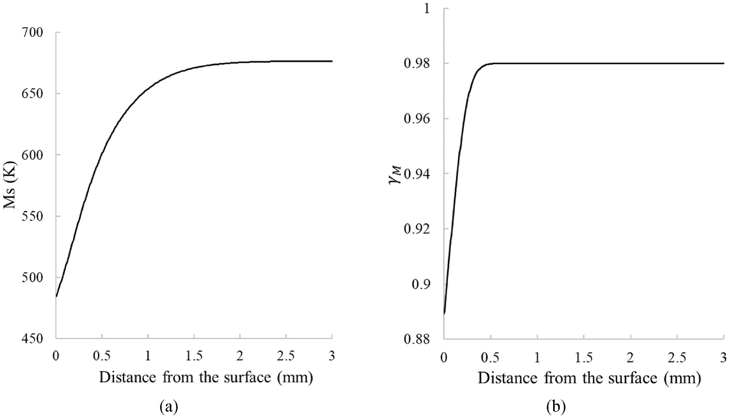
Ms increases from the surface of the sample to about 1 mm deep, from where it becomes constant, consistently with the carbon profile depicted in Figure 6a. The martensite fraction γM is lower near the outer surface because the local decrease in Ms slows down the onset of the martensitic transformation.
3.3.3 Mechanical fields at the end of the quenching process (step 5)
Figure 8a shows the repartition of the average stress σm = –PH along the symmetry axis. Compression can be observed below the sample surface (i.e. where carbon atoms have diffused), inducing a tensile stress elsewhere. There are two reasons for this behavior: Firstly, volume expansion is greater in the martensite-rich core, which tends to expand during transformation. The surface, which is cooler, less transformed, and thus mechanically more rigid, slows down this internal expansion. This blocking creates a state of compression on the surface and traction in the volume, which is consistent with observed tendencies (see, e.g., [12,14,19,35]). Secondly, dilatation linked to carbon diffusion also plays an important role, since it creates compression zones.
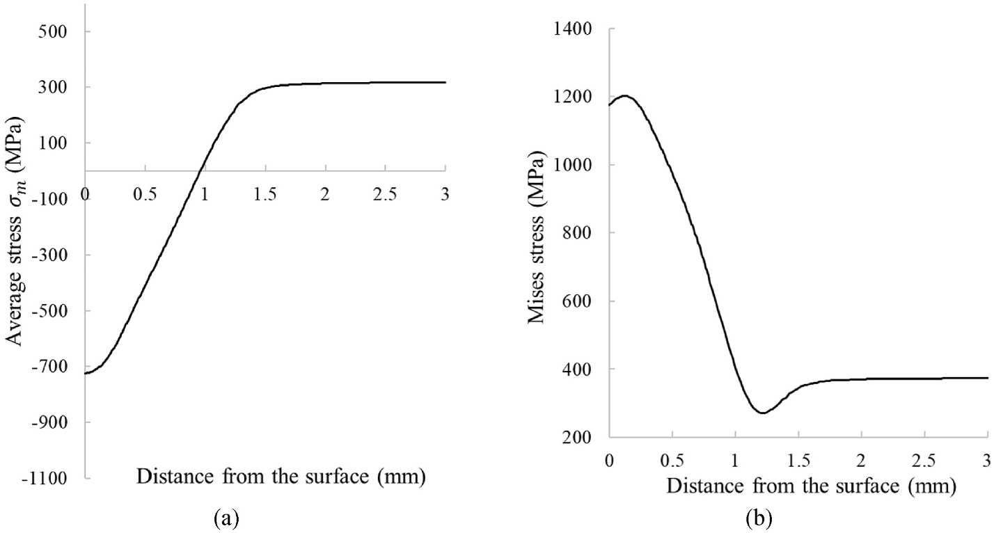
This compression is associated to a very high von Mises stress (Figure 8b), reaching its maximal value close to the surface, due to strong transformation-induced incompatibilities and the coexistence of martensite and retained austenite, which generate significant deviatoric stress components. The martensitic transformation deforms the material unevenly and in specific directions, since it occurs locally — some areas transform before others.
The surrounding material (still austenitic or already transformed) resists this deformation, creating internal stresses. It can be observed that, at depth, where the effects of cooling are less marked, residual stresses gradually decrease. This zone is generally characterized by low-amplitude stresses [12,14,19,35].
The evolution of stresses can be interpreted through the different strain contributions within the material:
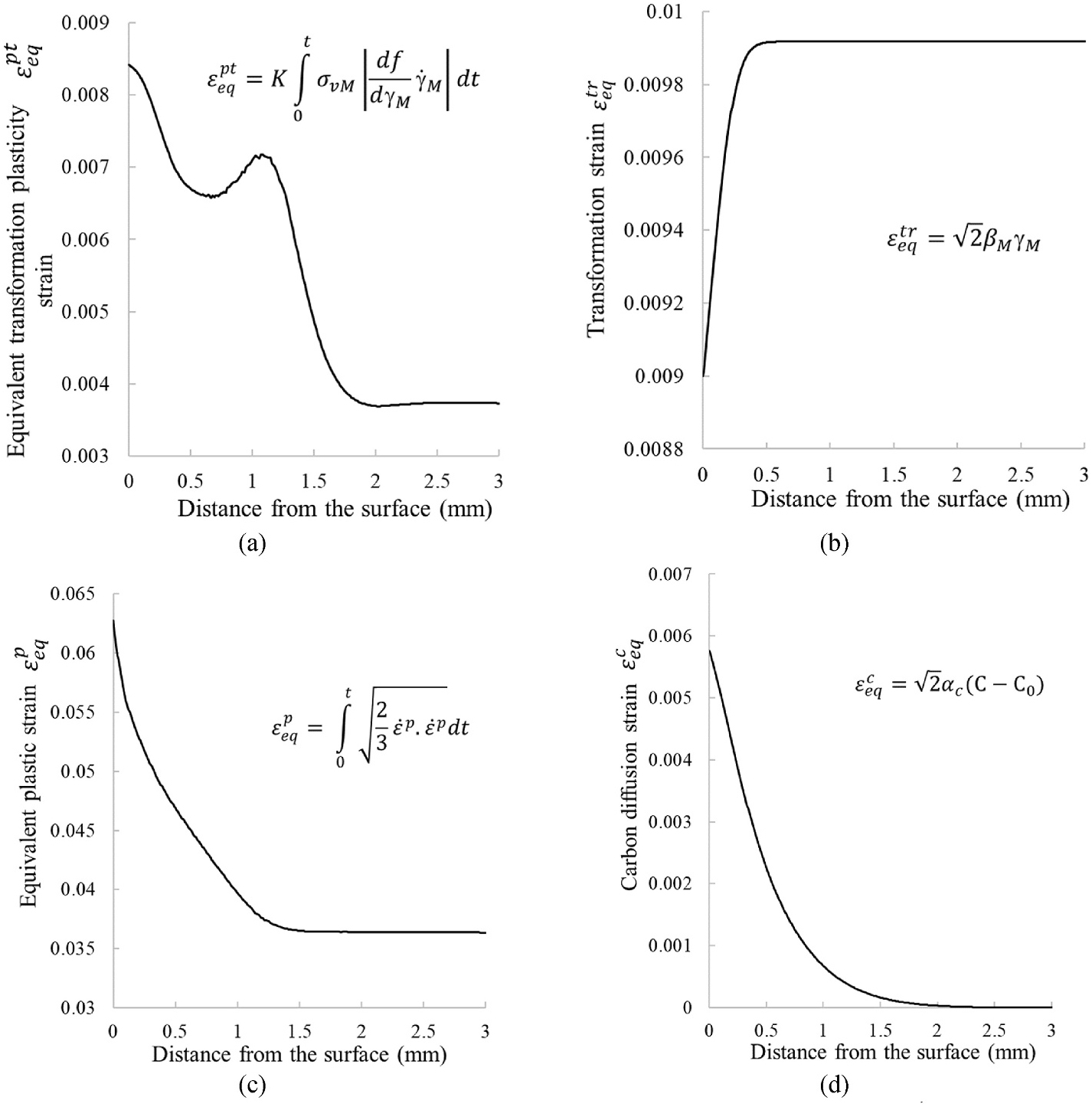
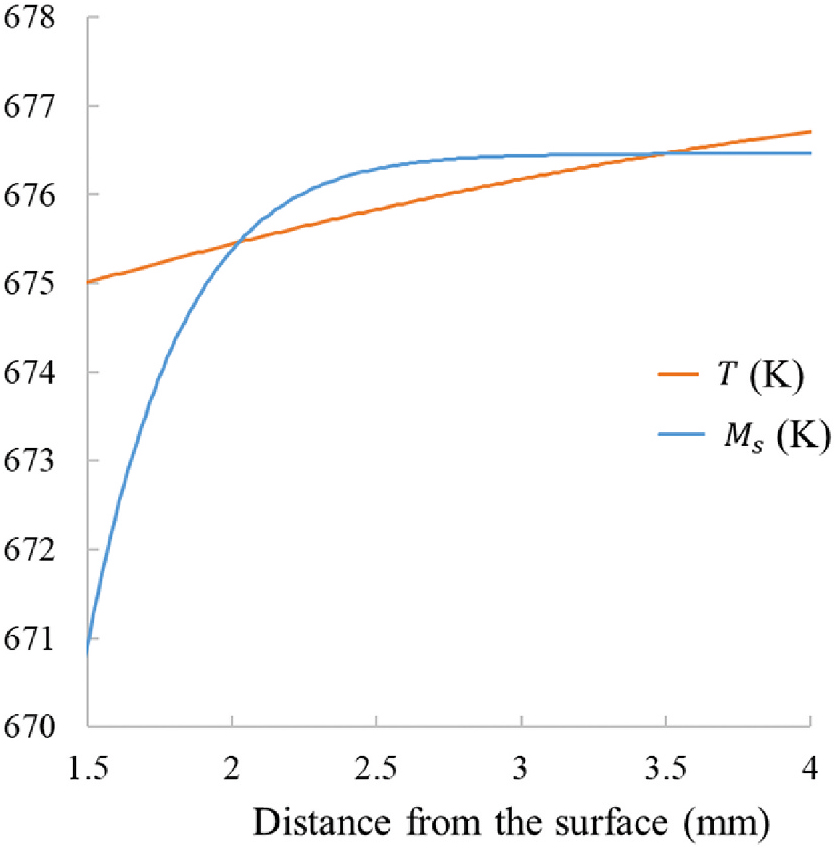
The equivalent transformation-induced plastic strain εpteq (Figure 9a) exhibits a pronounced maximum near the surface, followed by a local peak at about 1 mm in depth. The peak indicates the place where the beginning of the martensitic transformation takes place. During quenching, the temperature of the sample is not constant, but shows its maximum value at the axis of revolution. The martensitic transformation is triggered when the temperature becomes lower than Ms, which occurs at the peak after 100 seconds of quenching (see Figure 10). This peak is linked to a low von Mises stress value (Figure 8b).
The equivalent transformation strain εtreq (Figure 9b) is proportional to the martensite fraction (Figure 7b). It is minimal at the surface, where retained austenite remains, and maximal in the core, where the microstructure is predominantly martensitic. This induces additional mismatch with the less-transformed surface.
These gradients are accompanied by plasticity εceq, which is pronounced near the surface and strongly correlated with the von Mises stress (Figure 9c).
The equivalent carbon-induced strain εceq reaches its maximum at the surface and gradually decreases toward the sample’s center (Figure 9d). This trend directly reflects the carbon-concentration profile, where local expansion at the surface is mechanically constrained by the geometry and less enriched regions, leading to compressive stresses.
3.3.4 Impact of hydrostatic pressure on diffusion
Hydrostatic pressure on carbon diffusion has two main consequences: First, the carbon flux is modified (Equation 4) and carbon atoms tend to diffuse faster through areas in expansion (PH<0). Second, the carbon adsorption/absorption process is also modified: considering an instantaneous carbon adsorption/absorption reaction, the chemical potential equality between the gaseous carbon, and the atom in solution is given by the following boundary condition for C [40,41] in Equation 22:
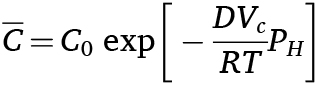
in which C0 represents the carbon-concentration values in the neighboring atmosphere (0.9 %, 0.85 and 0.75 %). The evolution of C is presented in Figure 11 with or without accounting for the impact of PH (i.e. considering respectively Vc ≠ 0 and Vc = 0).
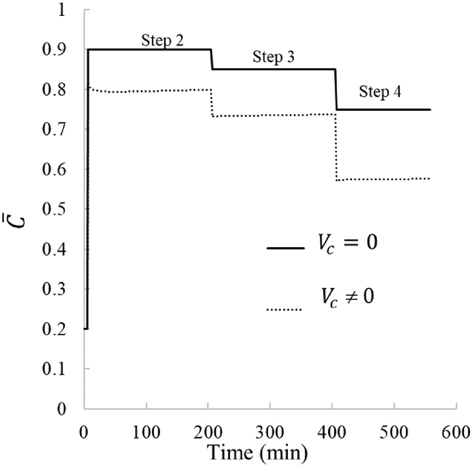
It is worth noting that Equation 22 has not been implemented in the flowchart presented in Figure 3, but computed using the previous PH-free results (week coupling).
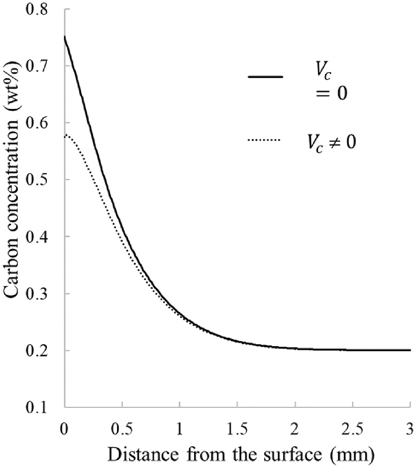
Figure 12 shows the comparison of the carbon-concentration profiles along the symmetry axis with and without PH, at the end of the diffusion process. It can be observed that the diffusion depth is not modified, but the level of C at the sample surface is significantly lower.
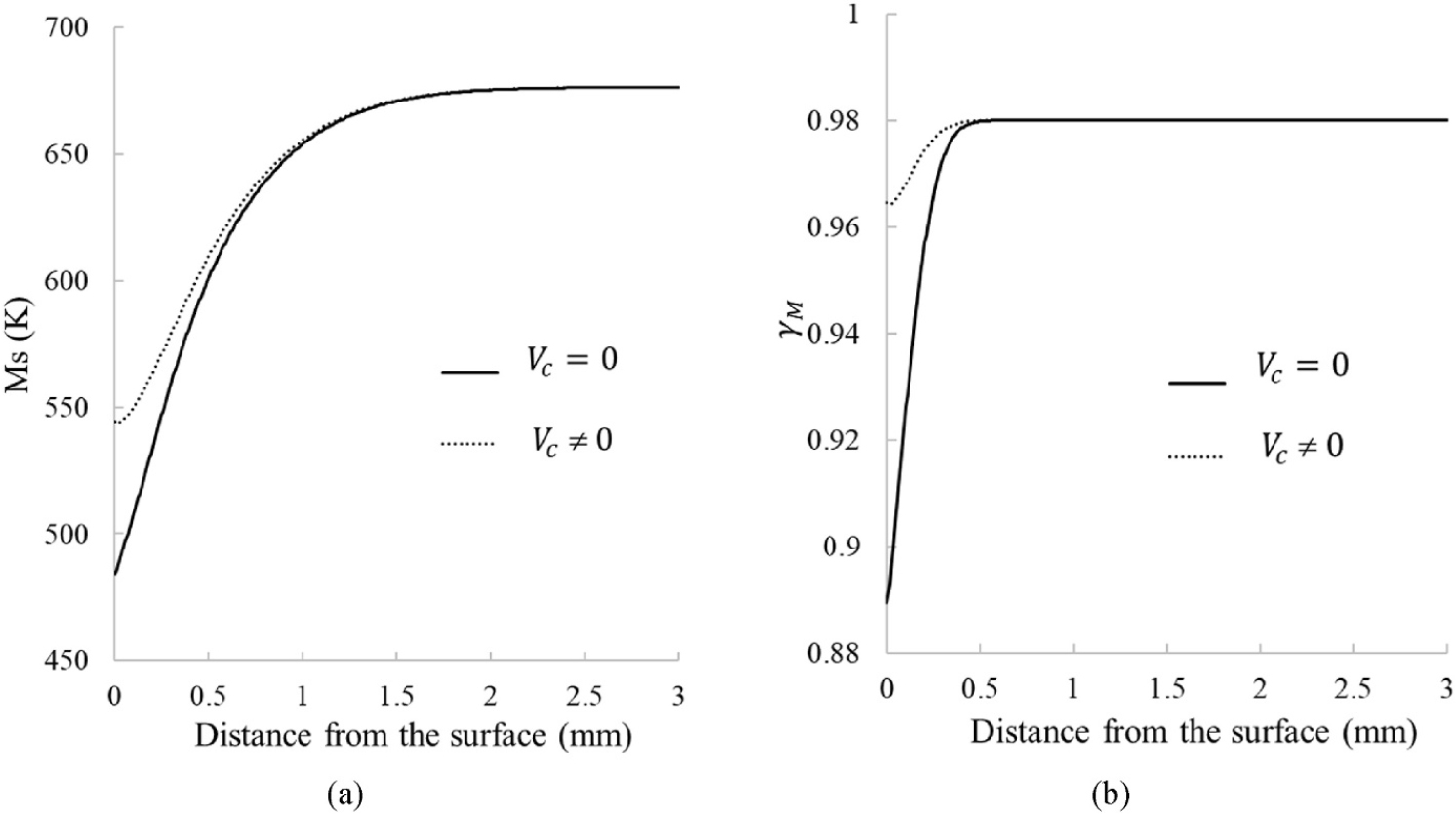
The consequences on the quenching process are illustrated in Figure 13, in which both Ms and γM evolution along the symmetry axis are plotted. Compared to the case without hydrostatic pressure, Ms starts from higher values at the surface, due to the lower carbon content, resulting from the hydrostatic compression that hinders carbon absorption in the sample. Consequently, the martensite fraction γM is also higher in this region, as the transformation is facilitated by the earlier intersection between temperature and Ms during cooling (which occurs at t = 80 seconds, at the same location than in the previous section).
The consequences on the mechanical fields and equivalent strains can be seen in Figure 14, in which mechanical fields and strains evolution along the symmetry axis are plotted at the end of the quenching step, and compared with the results without PH (previous section).
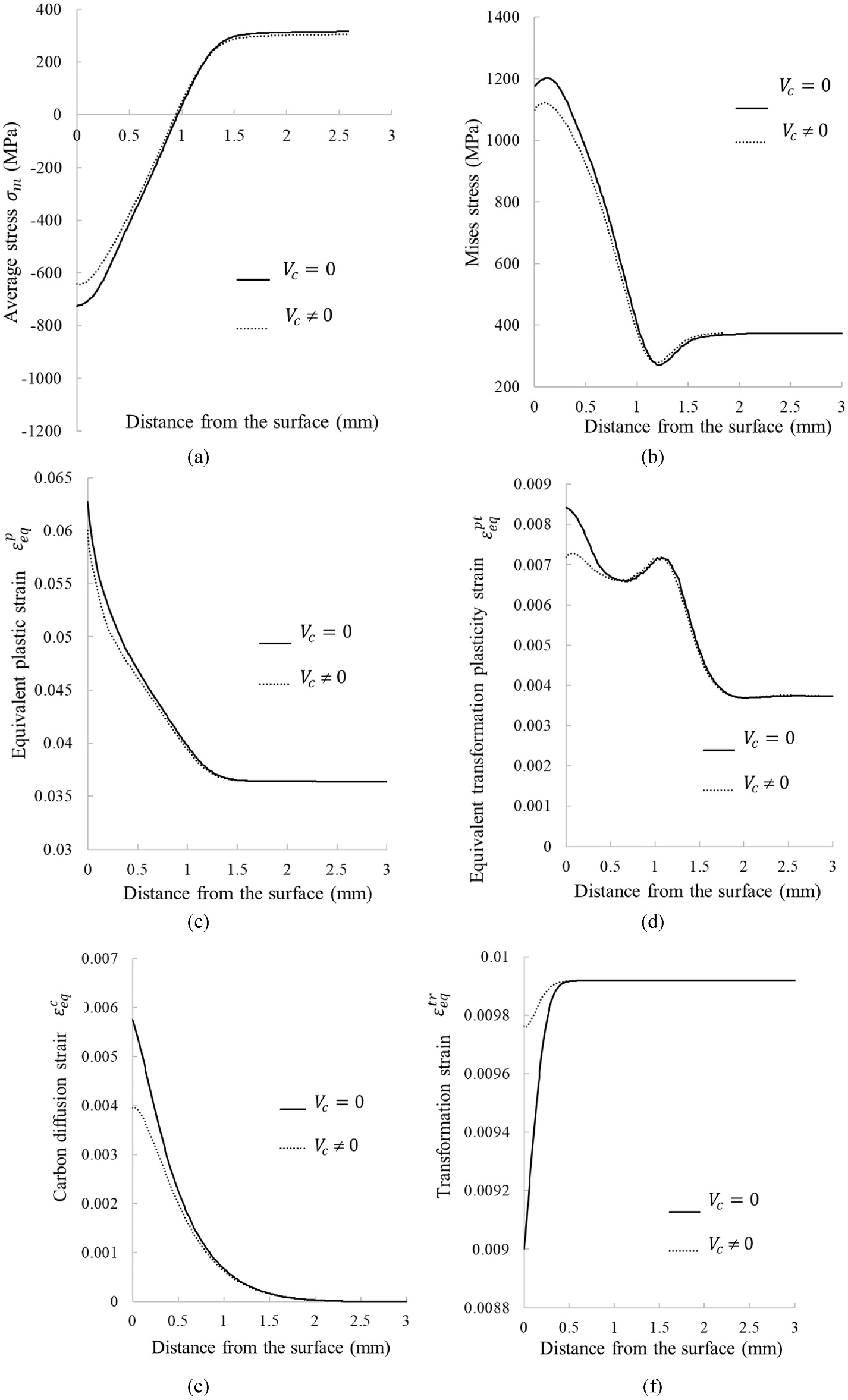
Due to the increase in the martensitic fraction γM at the surface, the transformation differential is reduced, thus reducing the average compressive stresses σm at the surface (Figure 14a). This attenuation is also reflected in von Mises stresses (Figure 14b). On the deformation side, diffusion deformation εceq directly follows the concentration profile, and clearly decreases with it (Figure 14e). Transformation strain εtreq (Figure 14f) increases at the surface, following the new distribution. At the same time, plastic transformation strain εpteq and plasticity strain εpeq become more homogeneous (Figure 14c and d), reflecting a reduction in internal mechanical gradients. Thus, hydrostatic pressure tends to reduce internal heterogeneities and residual stress peaks, making processing more mechanically balanced.
It should be noted the impact on PH diffusion is limited to the diffusion steps (2-4), for which the temperature T is sufficiently high. As soon as quenching occurs, diffusion tends to become negligible.
4 Conclusion
A model coupling heat transfer, mechanics, metallurgical change, and diffusion was implemented in the Abaqus finite element software to simulate the carburizing-quenching process. This implementation was achieved using user procedures, allowing for a coupled solution of the carbon diffusion process during the carburizing phases.
This model was then applied to a model configuration to illustrate the effect of stress and strain distribution on carburizing.
It was observed that, for the studied configuration, carbon penetrates only slightly, resulting in heterogeneous mechanical fields near the surface. In particular, a compression zone appears on the surface, associated with irreversible deformations related to the austenite-martensite phase change, for which a peak indicates the location where the phase change begins during the quenching phase.
The impact of hydrostatic pressure is limited to the surface region and has no impact on the diffusion depth. The consequences in terms of deformation are also limited to the surface, and tends to reduce irreversible deformation gradients, and, therefore, stresses.
From an engineering perspective, this stress redistribution tends to slightly reduce the surface hardness, due to the attenuation of the carbon gradient and transformation intensity. Consequently, neglecting hydrostatic pressure may lead to a slight overestimation of surface hardness and residual stress peaks, especially in cases where strong phase transformations occur near the surface. This suggests that, while the overall impact remains localized, accounting for hydrostatic effects can improve the accuracy of predictions for surface integrity and mechanical performance.
References
- X. Li, D. Ju, J. Cao, S. Wang, Y. Chen, F. He, et al. Effect of transformation plasticity on gear distortion and residual stresses in carburizing quenching simulation. Coatings, 11 (2021), p. 1224, 10.3390/coatings11101224
- H. Wang, B. Wang, Z. Wang, Y. Tian, R.D.K. Misra. Optimizing the low-pressure carburizing process of 16Cr3NiWMoVNbE gear steel. J Mater Sci Technol, 35 (2019), pp. 1218-1227, 10.1016/j.jmst.2019.02.001.
- P.F. Stratton, S. Bruce, V. Cheetham. Low-pressure carburizing systems: a review of current technology. BHM Berg- Hüttenmännische Monatsh, 151 (2006), pp. 451-456, 10.1007/BF03165206.
- T. Marray. Carbonitruration basse pression d’aciers et de pièces obtenues par la technologie MIM. Ecole nationale supérieure d’arts et métiers – ENSAM (2012) PhD thesis (in French). https://pastel.archives-ouvertes.fr/pastel-00840622. Accessed 20th Oct 2022.
- R. Mukai, D.-Y. Ju. Simulation of carburizing-quenching of a gear. Effect of carbon content on residual stresses and distortion. J Phys IV – Proc, 120 (2004), pp. 489-497, 10.1051/jp4:2004120056.
- M. Soleimani, A. Kalhor, H. Mirzadeh. Transformation-induced plasticity (TRIP) in advanced steels: a review. Mater Sci Eng A, 795 (2020), Article 140023, 10.1016/j.msea.2020.140023.
- S.-J. Lee, D.K. Matlock, C.J. Van Tyne. Comparison of two finite element simulation codes used to model the carburizing of steel. Comput Mater Sci, 68 (2013), pp. 47-54, 10.1016/j.commatsci.2012.10.007.
- H. Liu, X. Hu, J. Tang, Y. He, W. Shao, B. Sun, et al. A novel method for predicting carburizing and quenching deformation of the gear with the mandrel based on carburizing expansion strain and dynamic thermal boundary conditions of quenching. Surf Coat Technol, 494 (2024), Article 131377, 10.1016/j.surfcoat.2024.131377.
- H. Liu, J. Tang, C. Liu, Y. Liu, W. Jiang, B. Sun. Understanding the distinction between quenching and carburizing quenching stress field: evolution mechanism of quenching stress field influenced by carbon content in low-carbon alloy steel. Surf Coat Technol, 489 (2024), Article 131112, 10.1016/j.surfcoat.2024.131112.
- S. Yang, W. Chen, R. Liang. Residual stresses in gear form grinding by considering carburizing heat treatment: multi-field coupled numerical simulation and experimental verification. Int J Adv Manuf Technol, 131 (2024), pp. 4981-4999, 10.1007/s00170-024-13293-5.
- H. Wang, J. Wang, J. Xu, J. Gu, Z. Guo, N. Yu. Multi-field coupling simulation of vacuum carburizing and high-pressure gas quenching process. Heat Treat Surf Eng, 4 (2022), pp. 54-63, 10.1080/25787616.2022.2073051.
- S. Denis, P. Archambault, E. Gautier, A. Simon, G. Beck. Prediction of residual stress and distortion of ferrous and non-ferrous metals: current status and future developments. J Mater Eng Perform, 11 (2002), pp. 92-102, 10.1007/s11665-002-0014-2.
- E. Wołowiec-Korecka. Modeling methods for gas quenching, low-pressure carburizing and low-pressure nitriding. Eng Struct, 177 (2018), pp. 489-505, 10.1016/j.engstruct.2018.10.003.
- S. Qin, H. Ma, L. Wang. Stress field simulation and its experimental verification of carburizing-quenching process performed on 18CrNiMo7-6 steel. Mater Sci, 29 (2023), pp. 167-175, 10.5755/j02.ms.30932.
- B. Iżowski, A. Wojtyczka, M. Motyka. Numerical simulation of low-pressure carburizing and gas quenching for pyrowear 53 steel. Metals, 13 (2023), p. 371, 10.3390/met13020371.
- Y. Liu, J. Tang, H. Liu, W. Jiang. The influence of carbon content gradient and carbide precipitation on the microstructure evolution during carburizing-quenching-tempering of 20MnCr5 bevel gear. Surf Coat Technol, 494 (2024), Article 131387, 10.1016/j.surfcoat.2024.131387.
- J. Li, Y. Xu, Y. Liu, H. He. Investigation of non-uniformity of temperature distribution and phase transformation in spiral bevel gears during carburizing and quenching. J Mater Sci, 59 (2024), pp. 609-630, 10.1007/s10853-023-09182-z.
- Y. Wang, J. Gong. Measurement and calculation of carbon concentration and diffusion-induced stress in stainless steel after low temperature gas carburizing. Acta Met Sin, 50 (2014), pp. 409-414, 10.3724/SP.J.1037.2013.00537.
- J. Chen, Z. Zuo, S. Zhou, X. Wang, Y. Chen, G. Ling. Study on the compressive stress retention in quenched cam of 100Cr6 steel based on coupled thermomechanical and metallurgical modeling. Materials, 14 (2021), p. 5912, 10.3390/ma14205912.
- W. Shao, M. Yi, J. Tang, S. Sun. Prediction and minimization of the heat treatment induced distortion in 8620H steel gear: simulation and experimental verification. Chin J Mech Eng, 35 (2022), p. 126, 10.1186/s10033-022-00802-4.
- D.-W. Kim, H.-H. Cho, W.-B. Lee, K.T. Cho, Y.-G. Cho, S.-J. Kim, et al. A finite element simulation for carburizing heat treatment of automotive gear ring incorporating transformation plasticity. Mater Amp Des, 99 (2016), p. 243, 10.1016/j.matdes.2016.03.047.
- D.-Y. Ju. Residual stress and distortion: designing for control of. Encycl. Iron steel their alloys online version. CRC Press (2016).
- J. Teixeira, K. Jeyabalan, G. Geandier, J. Dulcy, B. Denand, M.-R. Chini, et al. In situ HEXRD experimental study and prediction of microstructures and internal stresses during heat treatment of carburized and carbonitrided low-alloyed steels. Acta Mater, 275 (2024), Article 120065, 10.1016/j.actamat.2024.120065.
- J. Wang, S. Yang, J. Li, D. Ju, X. Li, F. He, et al. Mathematical simulation and experimental verification of carburizing quenching process based on multi-field coupling. Coatings, 11 (2021), p. 1132, 10.3390/coatings11091132.
- Y. Yuan, Q. Zhang, Y. Xue, Y. Jiang, K. Liu, X. Shen, et al. Effects of high temperature tempering on microstructure and hardness distribution on 18Cr2Ni4WA alloy steel heavy-duty gears: numerical simulation and experiments. J Phys Conf Ser, 2549 (2023), Article 012028, 10.1088/1742-6596/2549/1/012028.
- Dassault Systèmes Simulia Corp. ABAQUS/Standard user’s manual. United States (2022).
- Dassault Systèmes Simulia Corp. ABAQUS user subroutines reference guide. United States. (2022).
- 28.J. Wijnen, J. Parker, M. Gagliano, E. Martínez-Pañeda. A computational framework to predict weld integrity and microstructural heterogeneity: application to hydrogen transmission. Mater Des, 249 (2025), Article 113533, 10.1016/j.matdes.2024.113533.
- J.C.M. Li, R.A. Oriani, L.S. Darken. The thermodynamics of stressed solids. Z Für Phys Chem, 49 (1966), pp. 271-290, 10.1524/zpch.1966.49.3_5.271.
- M. Jiří, N. Iva, Š. Pavel. Calculation of carbon diffusion for cementation of gear wheels. MM Publ (2018), pp. 2441-2450, 10.17973/MMSJ.2018_10_201826.
- S.-J. Lee, D.K. Matlock, C.J. Van Tyne. An empirical model for carbon diffusion in austenite incorporating alloying element effects. ISIJ Int, 51 (2011), pp. 1903-1911, 10.2355/isijinternational.51.1903.
- D.P. Koistinen, R.E. Marburger. A general equation prescribing the extent of the austenite-martensite transformation in pure iron-carbon alloys and plain carbon steels. Acta Metall, 7 (1959), pp. 59-60, 10.1016/0001-6160(59)90170-1.
- J. Mazur. Lattice parameters of martensite and of austenite. Nature, 166 (1950), p. 828, 10.1038/166828a0.
- M. Yaakoubi, M. Kchaou, D. Fakhreddine. Simulation of the thermomechanical and metallurgical behavior of steels by using ABAQUS software. Comput Mater Sci, 68 (2013), pp. 297-306, 10.1016/j.commatsci.2012.10.001.
- H. Zhong, Z. Wang, J. Gan, X. Wang, Y. Yang, J. He, et al. Numerical simulation of martensitic transformation plasticity of 42CrMo steel based on spot continual induction hardening model. Surf Coat Technol, 385 (2020), Article 125428, 10.1016/j.surfcoat.2020.125428.
- Y. Charles, H.T. Nguyen, M. Gaspérini. FE simulation of the influence of plastic strain on hydrogen distribution during an U-bend test. Int J Mech Sci, 120 (2017), pp. 214-224, 10.1016/j.ijmecsci.2016.11.017.
- E. Vasikaran, Y. Charles, P. Gilormini. Implementation of a reaction-diffusion process in the Abaqus finite element software. Mec Ind, 21 (2020), p. 508, 10.1051/meca/2020010.
- S. Bian, J. Mougenot, Y. Charles, X. Bonnin, T. Wauters, R. Pitts. Hydrogen retention in ITER’s Diagnostic first wall submitted to cyclic thermomechanical loadings. Procedia Struct Integr, 42 (2022), pp. 172-179, 10.1016/j.prostr.2022.12.021.
- H. Qvarnström. Technical note: a mathematical formula for transformation between the steel hardness scales of rockwell C and Vickers. J Heat Treat, 7 (1989), pp. 65-67, 10.1007/BF02833189.
- Y. Charles, H.T. Nguyen, M. Gaspérini. Comparison of hydrogen transport through pre-deformed synthetic polycrystals and homogeneous samples by finite element analysis. Int J Hydrogen Energy, 42 (2017), pp. 20336-20350, 10.1016/j.ijhydene.2017.06.016.
- E. Martínez-Pañeda, A. Díaz, L. Wright, A. Turnbull. Generalised boundary conditions for hydrogen transport at crack tips. Corros Sci, 173 (2020), Article 108698, 10.1016/j.corsci.2020.108698.
- M. Jung, S. Oh, Y.-K. Lee. Predictive model for the carbon concentration profile of vacuum carburized steels with acetylene. Met Mater Int, 15 (2009), pp. 971-975, 10.1007/s12540-009-0971-1.
- D.-W. Kim, Y.-G. Cho, H.-H. Cho, S.-H. Kim, W.-B. Lee, M.-G. Lee, et al. A numerical model for vacuum carburization of an automotive gear ring. Met Mater Int, 17 (2011), pp. 885-890, 10.1007/s12540-011-6004-x.
- S.-J. Lee, C.J. Van Tyne. A kinetics model for martensite transformation in plain carbon and low-alloyed steels. Metall Mater Trans A, 43 (2012), pp. 422-427, 10.1007/s11661-011-0872-z.
- O. Karabelchtchikova, R.D. Sisson. Carbon diffusion in steels: a numerical analysis based on direct integration of the flux. J Phase Equilibria Diffus, 27 (2006), pp. 598-604, 10.1007/BF02736561.
- Y. Yan, Y. Xue, W. Yu, K. Liu, M. Wang, X. Wang, et al. Predictions and experiments on the distortion of the 20Cr2Ni4A C-ring during carburizing and quenching process. Materials, 15 (2022), p. 4345, 10.3390/ma15124345.
- A. Rumony, A. Szlancsik, D. Kovács. Verification of the simulated carburizing process in different bore sizes. Coatings, 13 (2023), p. 1019, 10.3390/coatings13061019.
- Z. Li, B.L. Ferguson, E. Lee, S. Habean, J. Meyer. Sources of heat treatment distortion and approaches for distortion reduction during quench hardening process. ASM International (2024), pp. 132-138, 10.31399/asm.cp.ifhtse2024p0132.
- Z. Yingtao, T. Zirong, H. Lei, M.H. Mahdipanah, W. Yanjie. Real-time prediction method of carbon concentration in carburized steel based on a BP neural network. Heat Treat Surf Eng, 6 (2024), Article 2350184.