


Automobile manufacturers increasingly require components with greater accuracy for use in sophisticated applications. To meet these increased requirements, press hardening was developed, and there are continued advancements in this field of applications.
Inductive fixture hardening
EMA-Indutec developed a new process that combines the benefits of induction heating/hardening with the advantages of a fixture or press hardening process. The benefits of induction hardening include:
- Heat created directly within a workpiece
- No transmission losses
- Energy savings
- High production rates
- Fast, easy-to-control process/heating
- No emissions
Some adverse effects of heating a workpiece to about 900-950°C followed by hardening include:
- Dimensional changes due to thermal expansion
- Distortion due to asymmetric shapes
- Distortion due to asymmetric hardness patterns
- Volume expansion (about 1 percent) due to the martensite transformation
- Tensile stresses inside the workpiece due to machining and fabrication steps prior to hardening
All preexisting internal tensile stresses are released during heating and hardening, especially in thin-walled workpieces. Eliminating these nearly unavoidable effects requires time-consuming, expensive rework. To complicate matters further, rework (such as grinding and straightening) must be carried out on hardened surfaces.
Inductive mandrel-hardening process
EMA-Indutec developed induction fixture-hardening machines mainly for round and cylindrical workpieces such as sliding sleeves. The common process for handling carburized parts is shown in Figure 1.
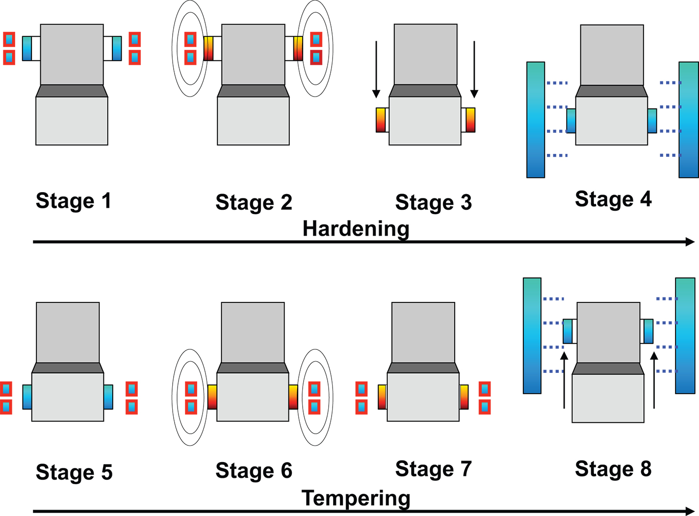
An oval or noncircular sliding sleeve is placed onto a nonconductive centering and holding device (Stage 1) and inductively heated to about 900°C (Stage 2). After a certain dwell time to achieve a uniform, homogeneous temperature, the workpiece is driven onto the calibration mandrel (Stage 3) immediately followed by extensive cooling using a polymer-based quenching medium (Stage 4). Stages 1 to 4 illustrate the inductive hardening process resulting in a cool workpiece, which is shrunk onto the calibration mandrel made of stainless steel.
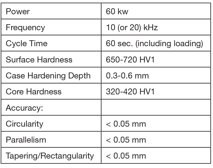
In the tempering process, an inductor is placed around the assembly of the sliding sleeve and calibration mandrel (Stage 5) and generates tempering heat inside the workpiece (Stage 6). With increasing temperature, the sliding sleeve expands marginally, creating a minimal gap (Stage 7) that enables removing the sleeve from the plug without affecting the precise, accurate surface of the calibration mandrel; a spring-driven force is sufficient (Stage 8). At the end of the hardening and tempering procedure, the sliding sleeve can be cooled down to room temperature. Table 1 shows typical process parameters.
Inductive press-hardening process
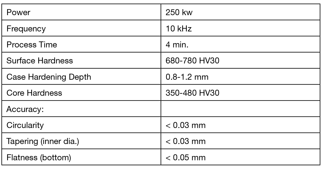
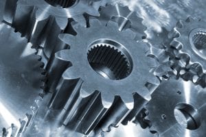
A new process was developed for handling crown wheels but is not limited to these parts. All workpieces requiring flat, even surfaces (Figure 3) can thus be corrected to accurate final dimensions while hardening. In principle, the new device works in a similar manner as a conventional machine. In addition, there are strong bottom and upper fixtures that contact the hot workpiece, pressing it while quenching. Stages 3 and 4 of Figure 2 show the additional fixtures. After quenching (Stage 4), the fixtures are no longer necessary and are removed to allow tempering (Stages 5 and 6). Process parameters and achieved results are shown in Table 2.


The new equipment provides two benefits compared with conventional fixture hardening. In most conventional processes, workpieces are heated in a gas-fired rotary hearth furnace and subsequently transported into the press. During the transfer period, parts cool down, whereas the inductor in the new machine allows heating up — from room temperature, if necessary, or to compensate temperature losses during the transfer. The time span from end of heating to first quench (which is relevant for quality) is minimized.
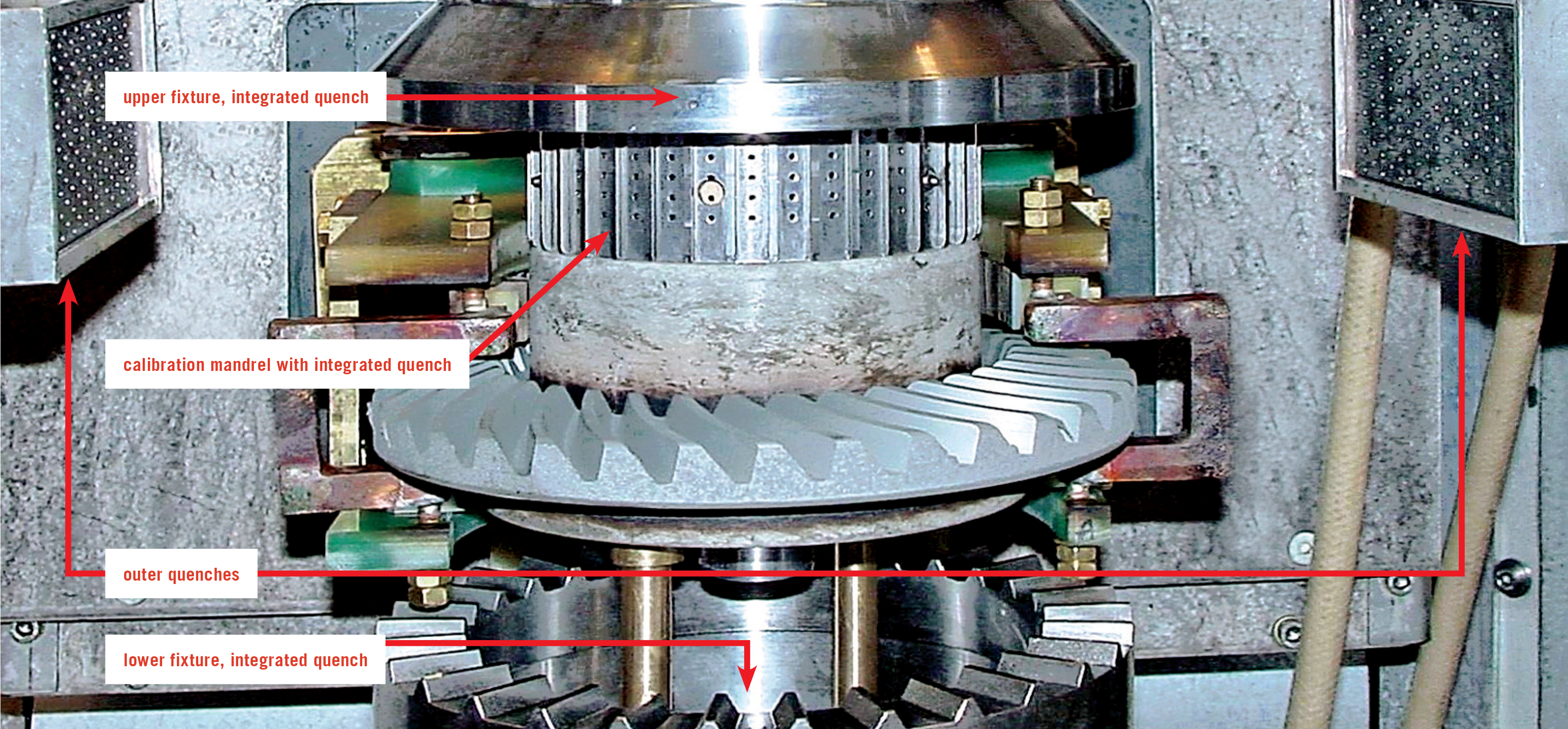
Also, the quenching technique is different, using four separately controllable quench circuits: through the bottom fixture, through the upper fixture, through the calibration mandrel, and from the outside (Figure 4). These four quenching options allow shape corrections, via cooling conditions such as various flow rates and different starting times, and respective dwell times. All quench systems are controlled individually by flow meters.
This device and process combines the advantages of induction hardening with the benefits of fixture hardening including:
- Integrating the process directly into the line
- One-piece-flow
- No delay on process start (no long-term heating up of a furnace)
- Energy savings due to short-term heating
- Excellent reproducibility due to good control options
- High precision of final workpiece dimensions
- Minimization of dimension failures and scrap
- Minimization of rework
Nevertheless, the process is based on carburized workpieces, so it is not necessary to change materials to higher carbon steels. The hardness patterns are not changed, therefore, the qualifying procedure is less cost-intensive compared with entirely new parts made of other materials and complete approval for a totally different process.
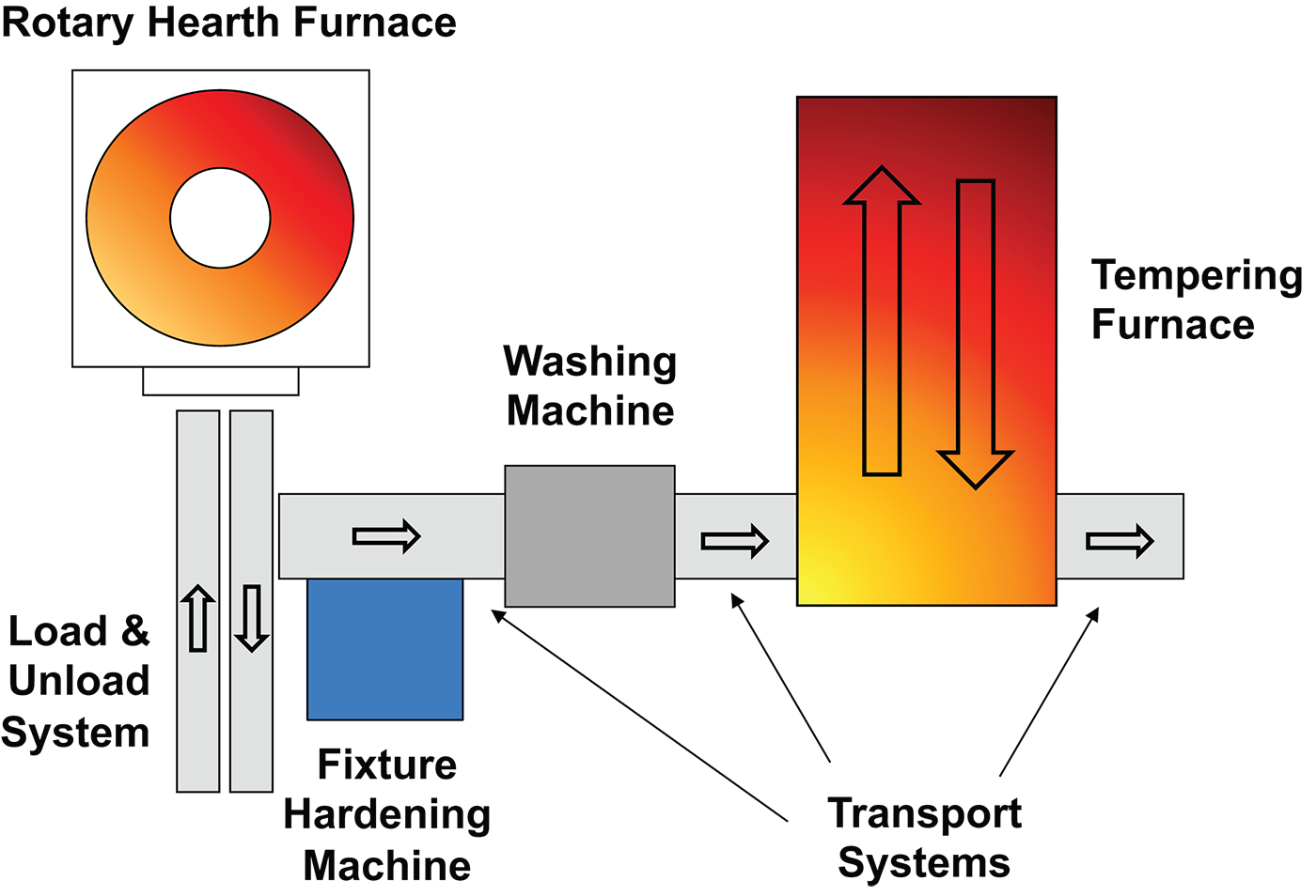
Plant design with rotary hearth furnace
A layout of a conventional furnace is shown in Figure 5. Main components are a rotary hearth furnace for carburization followed by a conventional fixture hardening machine for already heated workpieces. As conventional machines use oil as a quenchant, the next big component has to be a washing machine to clean oil from the parts. A mostly gas-fired tempering furnace follows. Individually controllable transport systems are necessary between all components.
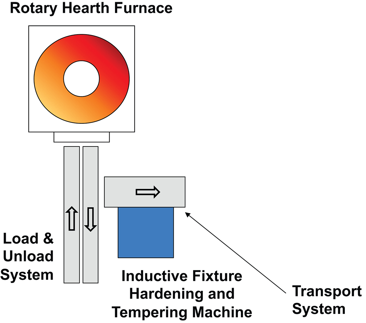
The number of components is drastically reduced in the inductive production plant Figure 6). Only the rotary hearth furnace and the new inductive fixture remain. The washing machine is superfluous because inductive hardening usually works with water-based liquid quenchants. So there is no need for subsequent washing of the heat-treated workpieces. The second component eliminated is the huge, expensive tempering furnace. Tempering is integrated in the new process, and no separate and/or additional energy is required. The inductor inside allows heating for hardening purposes as well as for tempering without any change except power level. Thus, the number of components and intermediate transport systems is reduced resulting in a considerable reduction of programming, sources of malfunction, and maintenance.
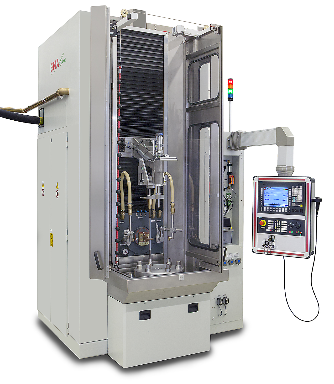
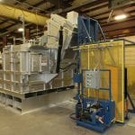
The hearth of the new process (the assembly consisting of the induction coil, lower and upper fixtures, and calibration mandrel) can be implemented in an EMA-Indutec nearly standard hardening machine shown in Figure 7.
Conclusion
The new process of combining the benefits of induction heating and hardening with the advantages of fixture hardening obtains highly precise workpieces with enormously reduced or eliminated rework.
References
- K. Heess et al., Maß- und Formänderungen infolge Wärmebehandlung, Expert Verlag, Renningen, 2007.
- G. Benkowsky, Induktionserwärmung, Verlag Technik GmbH, Berlin, 1990.
- A. Schreiner and O. Irretier, Praxishandbuch Härtereitechnik, Vulkan-Verlag, Essen, 2013.
- B. Nacke and E. Baake, Induktives Erwärmen, Vulkan-Verlag, Essen, 2014.


 general practice for CQI-9 and AMS2750E")


