


Post weld heat treatment on large pressure vessels is not a simple operation. When a vessel weighs hundreds of thousands of pounds, spans 70 to 100 feet in length, and carries a wall thickness measured in inches rather than fractions, every decision made during setup and execution has consequences. Do it right and you relieve residual weld stresses, improve toughness, and send a code-compliant vessel into service. Get it wrong and you may not know until something fails in the field.
Gulf Coast Combustion has specialized in on-site high-velocity direct gas fire PWHT since 2014. Over that time, it has heat treated vessels across a wide range of sizes and configurations. Most jobs involve vessels under 200,000 pounds. Some are considerably larger. Every one of them has followed the same structured execution standard, because consistency is what produces repeatable, code-compliant results.
Why Direct Gas Fire for Large Vessels
Large pressure vessels built to ASME Section VIII for oil and gas, chemical processing, and petrochemical service present a fundamental logistical problem for conventional furnace heat treating. A vessel that is 70 feet long and 16 feet in diameter cannot be moved to an outside furnace without significant cost, risk, and schedule impact. Oversized load permitting, specialized transport, rigging at both ends, and transit risk all compound the challenge. For many large vessels, transportation is not a practical option at all.
On-site heat treating solves this by bringing the equipment to the vessel. High-velocity direct gas fire combustion is particularly well-suited to large vessels because of its heating capacity and uniformity. Gas trains used operate at up to 10 million BTU, running on natural gas or liquid propane depending on site availability. High-velocity blowers circulate hot combustion gases inside the vessel, producing a convective heating environment that promotes temperature uniformity across the full shell length.
Electrical resistance heating is well established for smaller components and localized applications — pipe spools, flange faces, nozzle repairs. For large pressure vessels where the entire shell must reach uniform soak temperature, high-velocity gas fire provides the BTU capacity and internal circulation that resistance methods cannot match at scale.
Pre-Job Planning: The Execution Plan
Every job begins with a written execution plan developed before mobilization. The plan is specific to the vessel, not a generic template. It defines the governing code, wall thickness, material specification, soak temperature and tolerance, minimum soak time, heat-up and cool-down rate limits, thermocouple count and placement, burner assignment, insulation specification, and vessel support requirements. GCC execution plans are written to the specific requirements of each vessel and governing code, with management and QC sign-off required before any job starts.
The execution plan becomes the controlling document for the heat cycle. Any major deviation during execution requires client and management approval before work continues.
Thermocouple Placement: Accuracy Is Non-Negotiable
The entire compliance case for a heat-treatment cycle rests on demonstrating that the vessel reached the required soak temperature and held it for the required time. Inaccurate temperature measurement means inaccurate documentation, regardless of what actually happened to the steel.
GCC uses Type K thermocouples attached directly to the vessel surface using a capacitor discharge spot welder. This creates a true surface junction: The thermocouple wire is welded directly to the steel, making the vessel surface itself the measurement point. Methods that hold the thermocouple junction away from the surface through clips, banding wire, or welded nuts introduce measurement errors that can be significant under PWHT conditions.
Thermocouple placement follows a grid pattern across the vessel shell, with spacing not to exceed 15-foot intervals. Placement accounts for vessel geometry, nozzle locations, and any features — heavy forged nozzles, lifting lugs — that may behave differently from the main shell during heating. On complex jobs, those high-mass features get their own thermocouples and, where needed, supplemental electric resistance consoles to bring them to temperature in step with the rest of the vessel.
Thermocouple count scales with vessel size and complexity. A straightforward job might run 10 to 12 thermocouples. A vessel with heavy forged nozzles and multiple lifting lugs can require 24 or more.
Insulation: Controlling the Thermal Envelope
Insulation serves two functions in on-site PWHT: It reduces the BTU input required to reach and hold soak temperature, and it limits the temperature differential across the vessel surface during heating and cooling. Both matter for code compliance and metallurgical outcome.
GCC standard insulation is 1-inch, 8 lb/ft3 Kaowool ceramic fiber blanket applied in a single layer around the entire vessel surface with a minimum 3-inch overlap at all seams. The overlap accounts for thermal expansion of the vessel during the heat cycle and prevents gaps from opening as the steel grows. Insulation is secured using carbon steel banding straps and stud pins. All nozzles, attachments, and penetrations are individually insulated to prevent localized cold spots from pulling heat away from adjacent shell sections during soak.
Vessel supports require specific attention. Stationary structural supports cannot remain in contact with the vessel during PWHT. They create cold spots and restrict thermal growth. GCC uses temporary saddles on flat, smooth surfaces with high-temperature lithium grease between the saddle and the surface. The grease allows the vessel to grow and move freely as it expands during the heat cycle.
The Heat Cycle: Parameters and Discipline
The heat cycle for carbon steel pressure vessels under ASME UCS-56 involves three controlled phases: heat-up, soak, and cool-down. Each phase has specific rate and temperature requirements. Monitoring begins at 300°F and continues through cool-down completion at 800°F.
Heat-Up
The heat-up rate above 800°F is calculated as 400°F per hour divided by the governing wall thickness in inches, with an absolute maximum of 400°F per hour. A 2-inch wall allows 200°F per hour. A 3-inch wall allows approximately 130°F per hour. The calculation ties directly to wall thickness because thicker material requires more time for heat to conduct through the cross-section. Pushing heat-up rates on thick material creates gradients through the wall that introduce the very stresses PWHT is designed to relieve.
Soak
Soak temperature for most P-No. 1 carbon steels falls in the range of 1,100°F to 1,200°F. GCC standard is 1,150°F ±50°F. Soak begins when all thermocouples have reached the minimum soak temperature — not when the first one gets there. Every measurement point must be within the acceptable range before the hold clock starts.
Hold time is calculated from wall thickness: one hour per inch for the first two inches, then 15 minutes per additional inch beyond two inches. A 3-inch wall requires two hours and 30 minutes minimum.
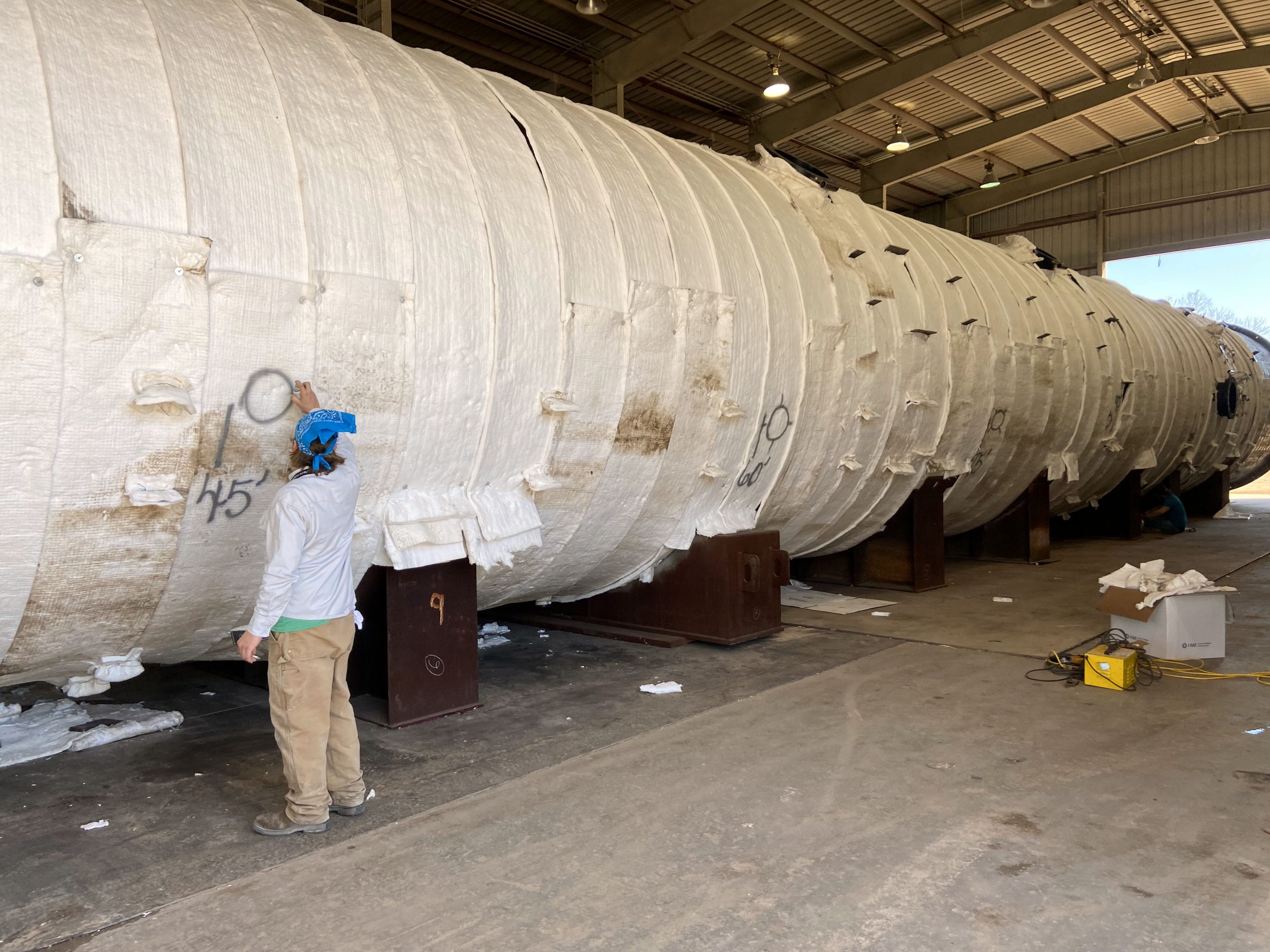
During soak, the maximum allowable temperature differential between the highest and lowest reading thermocouple is 250°F per code. Client specifications sometimes require tighter tolerances than this, and GCC executes to whatever the job demands. Temperature differential control is a function of insulation quality, burner placement, and active monitoring throughout the hold period. (See Figure 1)
Cool-Down
Cool-down rate from soak temperature to 800°F is calculated as 500°F per hour divided by wall thickness, with an absolute maximum of 500°F per hour. Below 800°F, free-air cooling is permitted, but burners remain in position until the vessel is cool enough to safely strip insulation. Pulling insulation early introduces rapid localized cooling that can re-introduce stress into the weld zone.
Case Study: A Large Vessel Job in Central Texas
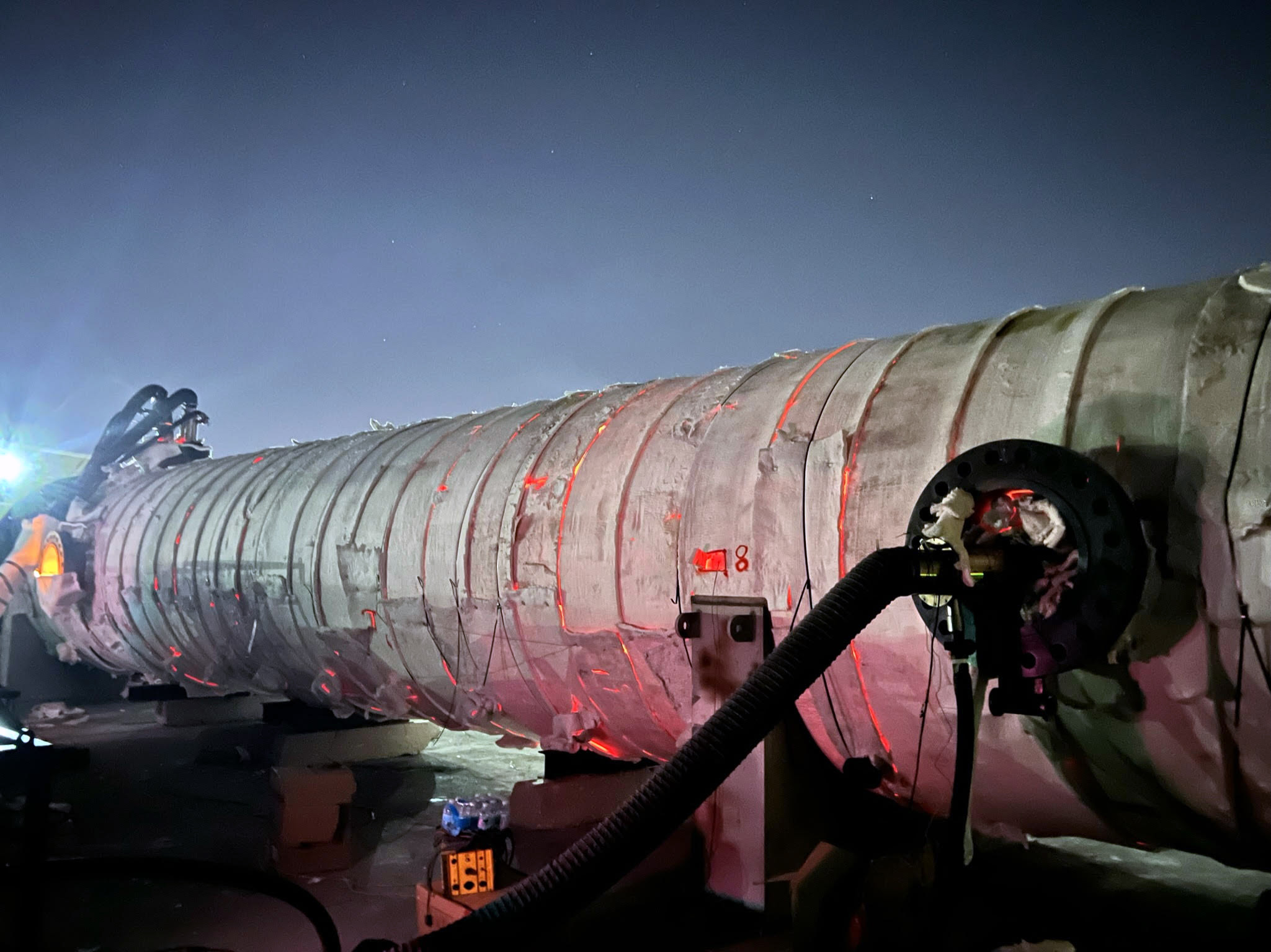
A long-standing GCC client in Central Texas required PWHT on a vessel measuring 69 feet shell-to-shell, 16.5 feet inside diameter, with a 3-inch governing wall thickness, constructed from SA-516-70N carbon steel and governed by ASME Section VIII. Empty weight: 621,000 pounds. (See Figure 2)
A vessel of this size could go to a furnace, but the logistics are significant. Moving 621,000 pounds requires a specialized heavy-haul operation, oversized load permits across multiple jurisdictions, and rigging at both ends. The cost and schedule impact would be substantial, and transit risk to a finished vessel is real. On-site heat treating was the right call.
GCC mobilized with seven high-velocity gas burners running on liquid propane — six at 6 million BTU each and one at 3 million BTU. With a 3-inch governing thickness, heat-up rate above 800°F was held to 130°F per hour. Eighteen thermocouples were attached directly to the vessel surface in a grid pattern across four rows plus both heads, with spacing not exceeding 15-foot intervals. The client specification required a maximum 100°F temperature differential during soak — tighter than the code maximum — and GCC executed to that standard.
The full vessel surface was wrapped in insulation with 3-inch overlaps at all seams. Eight temporary saddle supports with high-temperature lithium grease allowed the vessel to grow freely during the heat cycle. Monitoring ran on NIST-calibrated Chino strip chart recorders from 300°F through cool-down completion.
GCC documented this job via time lapse footage, available at https://youtu.be/UG9rjdfHpEE, which illustrates the full sequence from insulation and setup through firing, soak, and strip. The scale of the operation is difficult to convey in text alone.
Most vessels GCC heat treats on-site are under 200,000 pounds. Vessel length is a different story — 70 to 80 feet is common, and GCC has heat treated vessels exceeding 100 feet. The execution standard does not change with vessel size: The equipment count scales up; the thermocouple grid expands, and the planning depth increases, but the underlying discipline of controlled ramp rates, verified soak, and complete documentation is constant.
Documentation: The Permanent Record
Every GCC job produces a complete documentation package before the company leaves the site. Four components, every time: the heat treat record, the strip chart recorder trace, the recorder calibration certificate, and a job report log capturing any non-conformances during the process.
This documentation package is not a courtesy — it is the traceability record that quality systems, third-party inspectors, and ASME code compliance require. The paperwork is what proves the job was done correctly on a specific vessel on a specific date. If it is incomplete, illegible, or missing identification numbers, it fails — and failed paperwork is the same as no paperwork.
Technician Qualification
Equipment and procedures are only as reliable as the people running them. GCC maintains a four-level internal technician certification system. Level 1 is entry-level. Each subsequent level requires demonstrated field hours, written and practical examination, and expanding scope of independent authority. Level 4, the highest classification, requires a minimum of five consecutive years in the heat-treating industry. Level 4 technicians can make minor field adjustments to execution plans, manage multiple simultaneous jobs, and train lower-level technicians. Every job lead running a GCC heat treating job is level-certified.
The technician’s judgment matters in the field. Job sites do not always match what was anticipated during planning. Experienced technicians recognize when something developing requires a pause, a call to management, or a documented deviation.
Consistency as the Standard
On-site direct gas fire PWHT is harder than furnace heat treating. The temperature variables are real, the field conditions are unpredictable, and there is no controlled chamber to compensate for poor setup. Wind, ambient temperature, vessel orientation, burner placement — all of it affects the heat cycle in ways that a furnace environment simply does not present.
What makes the difference is not equipment alone. It is the consistency of the execution standard. A written plan specific to the vessel. Thermocouples attached to read true surface temperature. Insulation applied correctly to every nozzle and penetration. Heat-cycle parameters calculated from wall thickness and held within tolerance throughout. Documentation completed and signed before leaving the site.
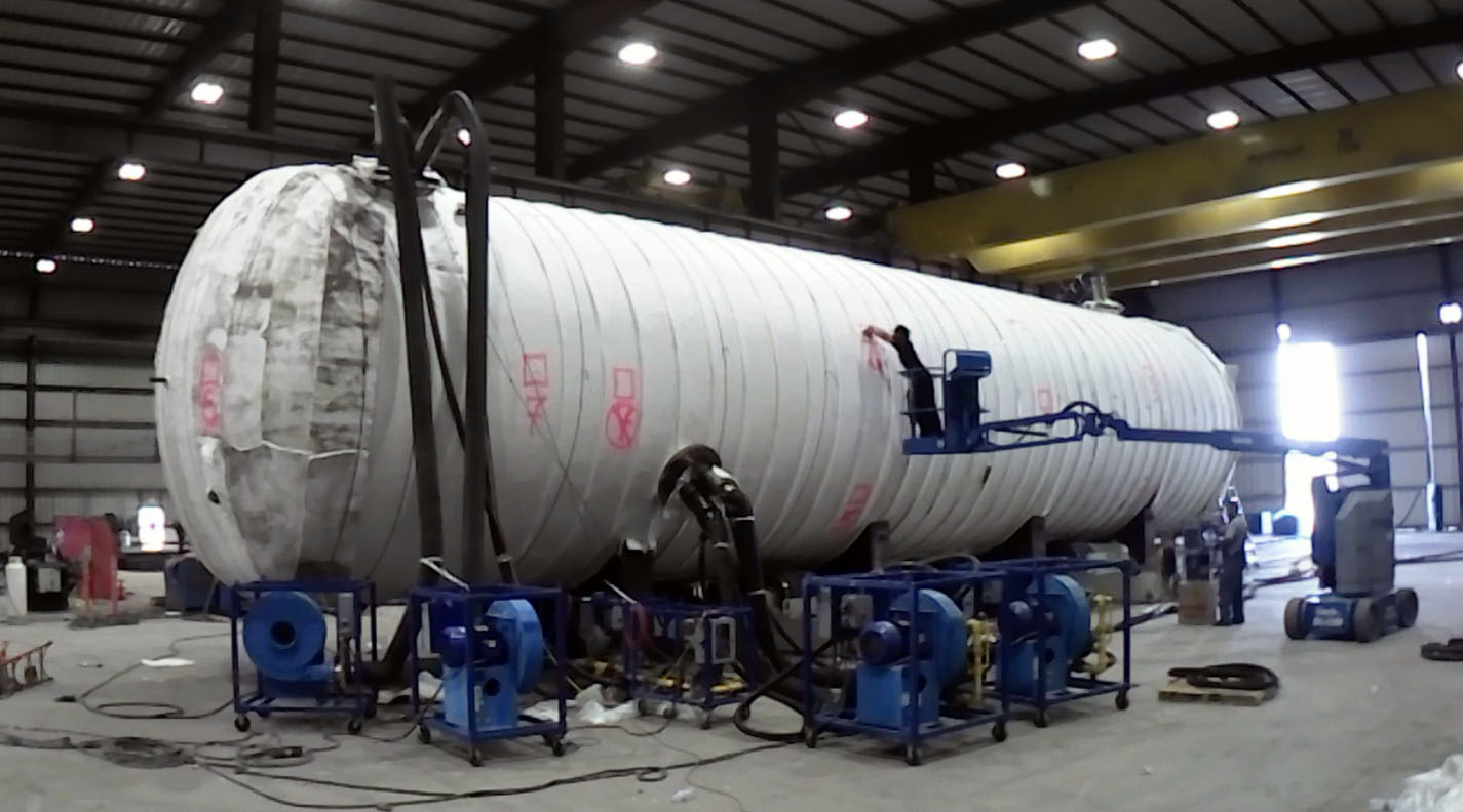
Every vessel GCC heat treats gets that standard. The execution does not change based on vessel size, client relationship, or schedule pressure. That consistency is what fabricators, quality managers, and inspectors can rely on. (See Figure 3)


 general practice for CQI-9 and AMS2750E")


