


In an increasingly competitive world, it is good to pause and ask: How can we do our work faster, better, and use fewer resources? Induction Tooling Inc. has disrupted the traditional approach to validating selective hardening inductors, getting them into production faster than ever before and with improved production results. The vision allows testing and validation to occur at the inductor manufacturer before it ever reaches the heat treater. The final product is a fully characterized and proven inductor, complete with production process settings and a metallurgical report from an ISO 17025 accredited commercial test laboratory specializing in induction heat treating. This high-quality report is suitable to forward to an end customer. Sample parts for show-and-tell or small lots for further testing are also commonly requested. Best of all, this occurs without breaking into production or tying up company personnel.
Mirroring the heat treaters’ production parameters, the inductor, commonly called a coil, can be characterized to produce a hardening pattern that meets the nominal case depth requirements. Meeting nominal requirements, rather than the minimum or maximum, gives the induction operation the greatest flexibility in manufacturing. Induction heat treating often encounters problem areas including sharp corners, fillets, holes, difficult runouts, deep case requirements, or thin walls. Addressing these issues before production actually solves problems before they can become issues.
About Inductors
The technology that goes into the design and manufacture of robust production-ready induction heat treating inductors incorporates both calculations and experience. The number of variables influencing the induction-hardening pattern produced by a specific power supply, inductor, and part geometry are extensive. In the time between receipt of an engineering drawing and hardening of production parts, the following steps must occur (see Figure 1):
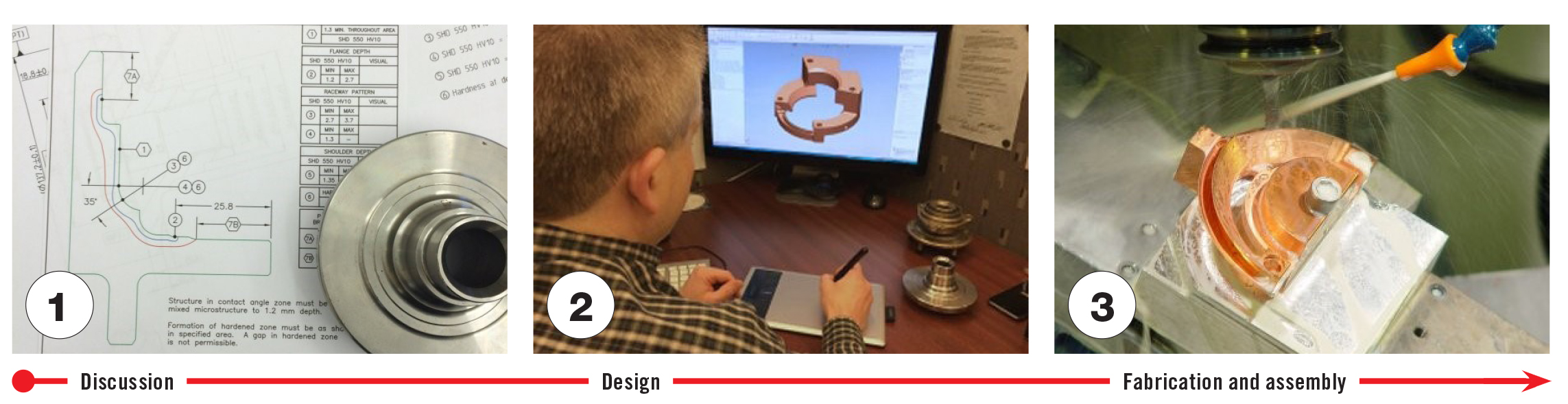
- Discussion regarding the induction-hardening requirements (engineering requirements, alloy, and part geometry), induction heating equipment (system capabilities and constraints), and material handling (throughput, part loading, etc.).
- Design of inductor including integrating clearances, equipment centerlines, part loading, and contacts. Expertise is required to design an inductor to produce the desired pattern. Generally, coils are designed slightly oversized so material can be removed rather than added to produce the required pattern if changes are required.
- Fabrication and assembly of fixtured tubular or machined copper for the inductor includes machining, brazing of joints, pressure and flow testing, and finalizing for production environments.
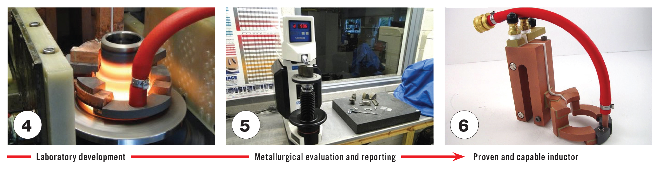
- Laboratory testing and characterizing. The induction-heating operator can control part position, air gap, power, and cycle time or scan rate to influence the induction-heating pattern created. A coil must be tested and the results confirmed before it can be used in production. If changes to the coil geometry are required (a process called characterizing the inductor), it is done during this stage.
- Metallurgical evaluation and reporting. Validation includes looking at the induction-hardened pattern using etching techniques to reveal the case depth and Rockwell hardness to verify hardness. If these are found acceptable, the microstructure, grain size, and microhardness profiles are checked to validate good microstructure transformation, checking for overheating and good case/core transition. If issues are noted, coil development must return to step 4.
- Capable and proven inductor. At the end of the cycle, the inductor should be capable of producing the required pattern in a documented and repeatable manner. Results would be validated and then approved by the final customer.
The sequence of testing, characterizing, and validating offers a great opportunity to reduce the time into production. Currently, this cycle may require the following process: For example, the inductor is sent to the induction heat-treating facility. This may involve breaking into production to set up and run the prototype part. Once the part is run, it must be checked to validate the settings. If it needs to be characterized, it must be returned to the inductor manufacturer for modifications and then returned to the induction heat-treating facility. If additional characterizing is necessary, it is returned to the induction house and then returned to the induction heat-treating facility. In a complex part geometry, changes in one area of the inductor will influence the pattern in another. This cycle may continue, using up resources and requiring interruptions to production schedules.
Instead of interrupting production at the heat-treating facility, the process can be developed at the inductor manufacturer. The production settings of power and frequency, quenchant, cycle time, and material handling can be matched to those used at the heat treater. If inductor modifications (characterization) are needed, they can be performed and revalidated at the inductor facility and then reverified on-site. With the addition of a commercial testing laboratory, a full metallurgical evaluation can be performed and results submitted in a format that can be forwarded directly from the heat treater to the end customer.
Multiple changes and validations are performed quickly by a staff dedicated to that purpose. Having all of these resources under one roof — design, fabrication, induction development, and metallurgical validation — is a disruptive method to improve production efficiency and significantly shorten the time to PPAP or production. The result is a fully characterized inductor, process parameters for the operator, prototype lots of processed parts, plus a metallurgical evaluation conducted by an ISO 17025 accredited testing laboratory specializing in induction heat treating.
The following are four examples of development work performed at Induction Tooling’s Induction Development Laboratory:
Roller Path Inductor Characterization
Large forged bearing and gear companies have found this service extremely useful for their products. Large bearing components (100 inches in diameter and up) are often made in lots of one with costs of tens of thousands of dollars when the parts reach the heat-treating operation. In addition, these are often manufactured under expedited conditions. The Induction Development Lab has been used repeatedly to develop processes that are close to production-ready for this purpose.
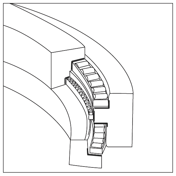
A three-row bearing (see Figure 2) is composed of three rings containing several bearing surfaces. The bold surfaces are the induction-hardened raceways. This discussion pertains to the lower roller path shown in the figure.
For this application, a field failure required the region of full case depth to be extended as close as possible to the fillet of the roller path for this replacement bearing (see Figure 3). The customer uses a 22 kHz frequency, which is not ideal for a deep case application. With modifications to the inductor, power level, and scan speed in the Induction Development Lab, full case depth was achieved at the location required by the roller path redesign.
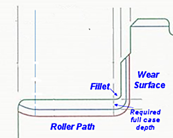
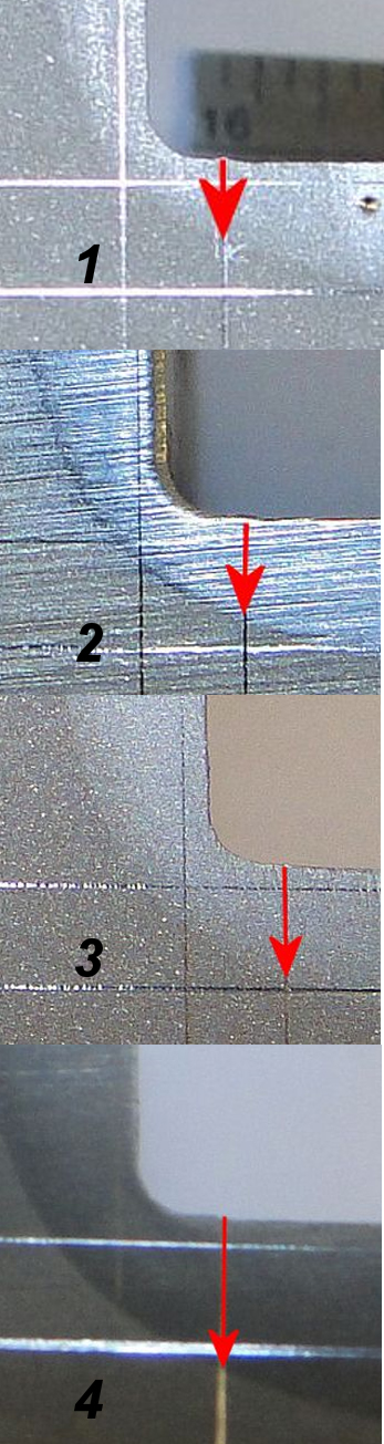
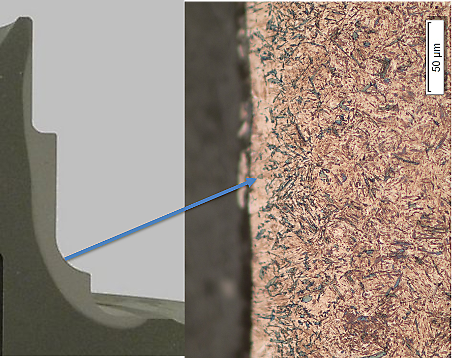
Figure 4 shows a cross-section through the induction-hardened roller path at the fillet. The samples were etched to show the induction-hardened case. The vertical and horizontal lines show the surface hardness and minimum case depth requirement locations. The red arrow is where full case depth is required. The macro-labeled #1 shows that the case is about half the desired case depth. As a result, the inductor geometry into the fillet was modified, and the power was increased by 10 percent to produce the case shown in #2, which is an improvement but still misses the required depth. The power was further increased, and the scan speed was decreased. The resulting pattern #3 meets the requirement; however, laminations needed to be removed from the coil to reduce the pattern depth on the wear surface and outer corner of the roller path. The final result is shown in #4, which meets the desired case depth requirement, exhibits sound metallurgical practice, and operates within the constraints of the customers’ production capabilities.
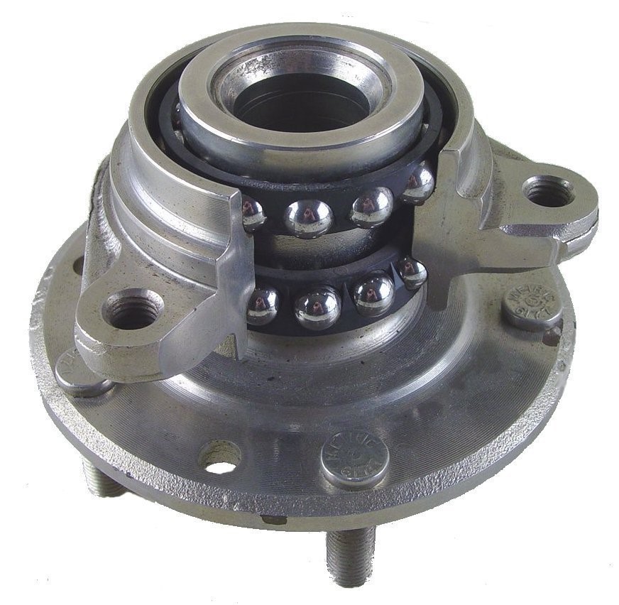
Wheel Bearing Spindle Characterization
Automotive wheel bearings (see Figure 5) are a safety-critical item with complicated geometries. The interior raceway is called the inner ring or spindle. The outer raceway is called the outer race or hub. A typical hardening pattern for the inner ring is shown in Figure 6 [1].
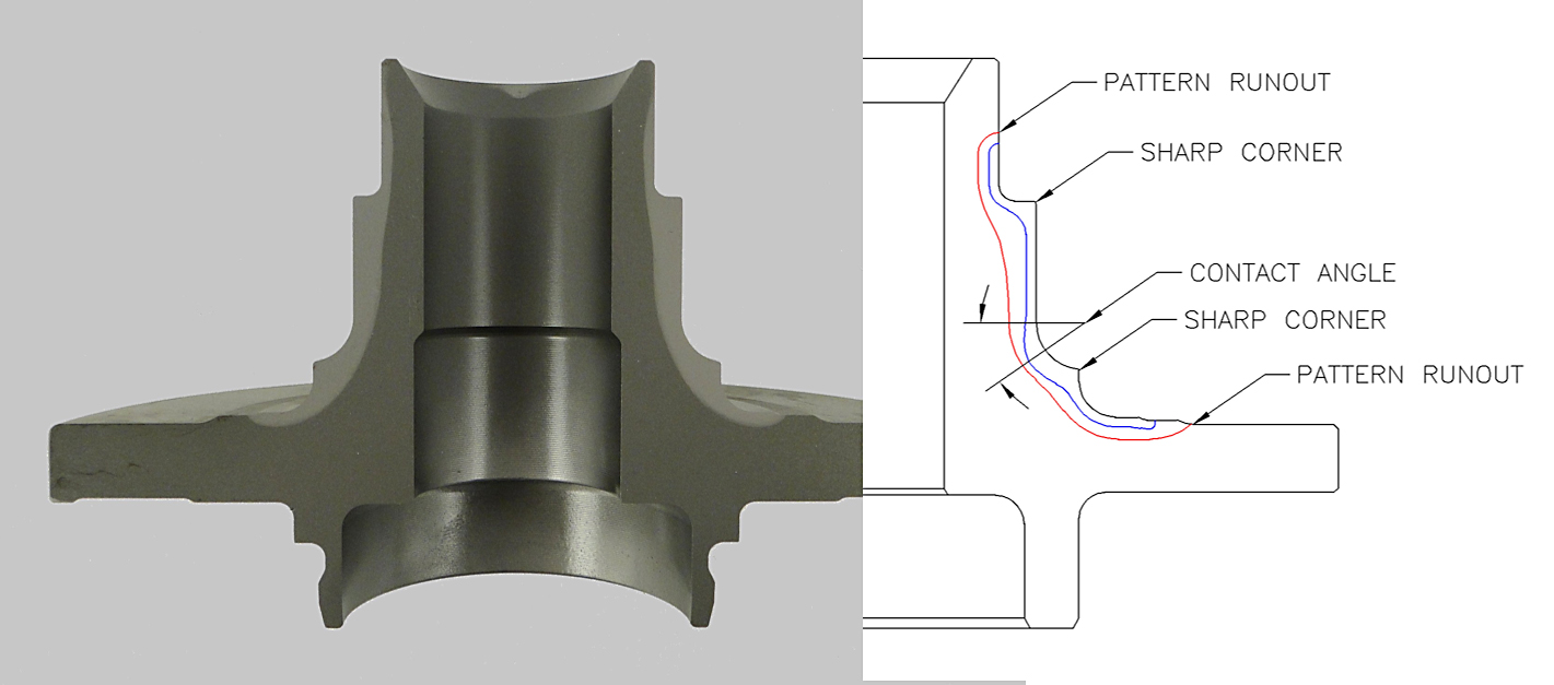
Wheel bearing geometries are often similar as they share many of the same features (see Figure 6). Three characteristics of concern include sharp corners at the raceway ends, convex contact angles, and occasionally problematic runout requirements. Characterizing hubs and spindles can be tricky, because changing the inductor dimension in one area may shift the induction field to a different area. These fields must be balanced across the part.
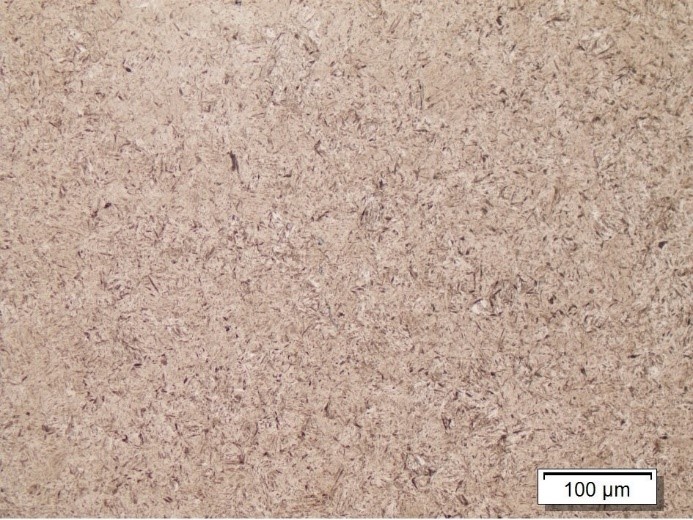
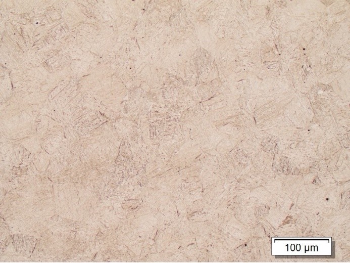
The following examines these three characteristics: First, overheating at the sharp corners. Corner geometries tend to overheat for two reasons: The electrical field is attracted to sharp geometry, and the heat conducts in from two surfaces. Figure 7 shows acceptable martensitic structure with an ASTM grain size of 7-8. Figure 8 shows an overheated structure with coarse martensite and an ASTM grain size of 4-5. Good inductor design controls the heat at these locations.
The second concern is control of microstructure in the contact angle. The contact angle is required to have optimal microstructure. The heating to austenite followed by effective quenching to form 100-percent martensite without the presence of transformation products is critical during development. Figure 9 shows how ineffective quenching can lead to the formation of bainite, a non-martensitic transformation product.
The third critical concern is the pattern runout. Runouts are where the hardening pattern needs to stop. A runout can be thought of as two competing interests. We want the coil to austenitize and fully transform the structure but also want the pattern to not heat the steel within a short distance. This is controlled with a combination of inductor design, placement, gapping, and quench.
Small Prototype Lots
Once the inductor is characterized and production parameters are identified, small-lot production runoff for parts used for life-cycle testing or similar requirements can be done in the Induction Development Lab. Induction Tooling is not a production heat treater and does not process parts for end use; however, there is a need for the ability to process small lots of parts for evaluation purposes. The parts are made to specification and validated.
Inductor-Life Improvement Projects
Inductors often are subjected to a punishing production environment. Inductor failures result in replacement costs and lost production. Existing coil designs can be modified to increase the inductor life. It is timely to accomplish this objective when changes to the hardened product or equipment changes require a new PAPP effort. Induction Tooling has increased the lives of numerous inductor configurations by removing braze joints, beefing up supports, or improving designs.
References
- “Design and Development of PPAP Ready Wheel Bearing Inductors.” S. J. Midea. Industrial Heating Magazine. May 2016.


 general practice for CQI-9 and AMS2750E")


