


Materials fracture occurs in all sectors of the economy — aerospace, nuclear, medical, transportation, oil and gas, petrochemical, commercial and residential buildings, etc. The annual economic cost of material failure is estimated to be in the billions in the United States and trillions globally. Some of the known historic failures are the tanker SS Schenectady, whose hull split in the middle; Aloha airlines; World War II Liberty ships (which had all-welded hulls); Boston molasses tank failure; F-111 aircraft; and the I-35 bridge in Minneapolis among others.
There are well-established techniques to measure conventional materials strengths such as yield strength, hardness, etc. However, material structure cannot solely rely on yield strength for design and performance.
Another materials strength property that is widely used these days is fracture toughness. Measuring fracture toughness is advantageous in quantitative analysis as it allows structural life assessment, and provides a safety factor and inspection criteria. Since World War II, there have been significant improvements in understanding fracture mechanics by measuring materials’ fracture toughness. Fracture mechanics, a field of study that includes fracture toughness, deals with the effect of defects on the load-bearing capacity of materials and structures. The approach is practical as it takes into consideration that all materials and structures have inherent defects. Practically, there are no defect-free engineering materials; defect should be part of any design and fit-for-service assessment. This technique is an advancement to the approach that only considered conventional materials strength. Defects in materials can be voids, inclusions, secondary phases, dislocations, grain boundary, and grain misfits in microstructural level. In macrostructural levels they can include surface finish, notches, scratches, materials boundaries, cracks, and environmental degradation.
Due to the lack of technology to quantify a variety of defects individually, all defects instead are treated as a notch and sharp crack. Griffith in the 1920s initially used an energy balance approach to quantify fracture mechanics in a stressed plate with a crack. George Irwin in 1950 used the stress intensity factor (K) to predict fracture behavior as K = σ √ πac , where σ is the tensile stress and ac is the critical crack length. In the linear-elastic approach, stress intensity factor is the proportionality constant that characterizes stress fields ahead of a crack tip [1]. To predict failure or fracture events, there is need to determine K, which is a function of materials properties, stresses, and defect size. K can be calculated by closed form analysis (theory of elasticity, numerical technique), finite element, estimation, handbooks, and experimental.
Testing
Different organizations such as American Society for Testing and Materials (ASTM), the Japan Society of Mechanical Engineers (JSME), the International Institute of Standard (ISO), and the British Standard Institute (BSI) have developed standards for measuring fracture toughness. Some of the early standards date to the 1970s. Fracture toughness under monotonic loading against temperature is measured for LEFM per ASTM E399 –Standard Test Method for Linear-Elastic Plane-Strain Fracture Toughness (KIC) of Metallic Materials. All standards published by different organizations have the same basic instrumentation for introducing cracks and measuring load and displacement, but there are subtle differences. The specification features specimen, specimen preparation and precracking, test fixturing and instrumentation, test procedure, test result evaluation, validity checks, and reporting [2]. The objective of fracture testing is to conduct a laboratory test and relate its behavior to a structural component.
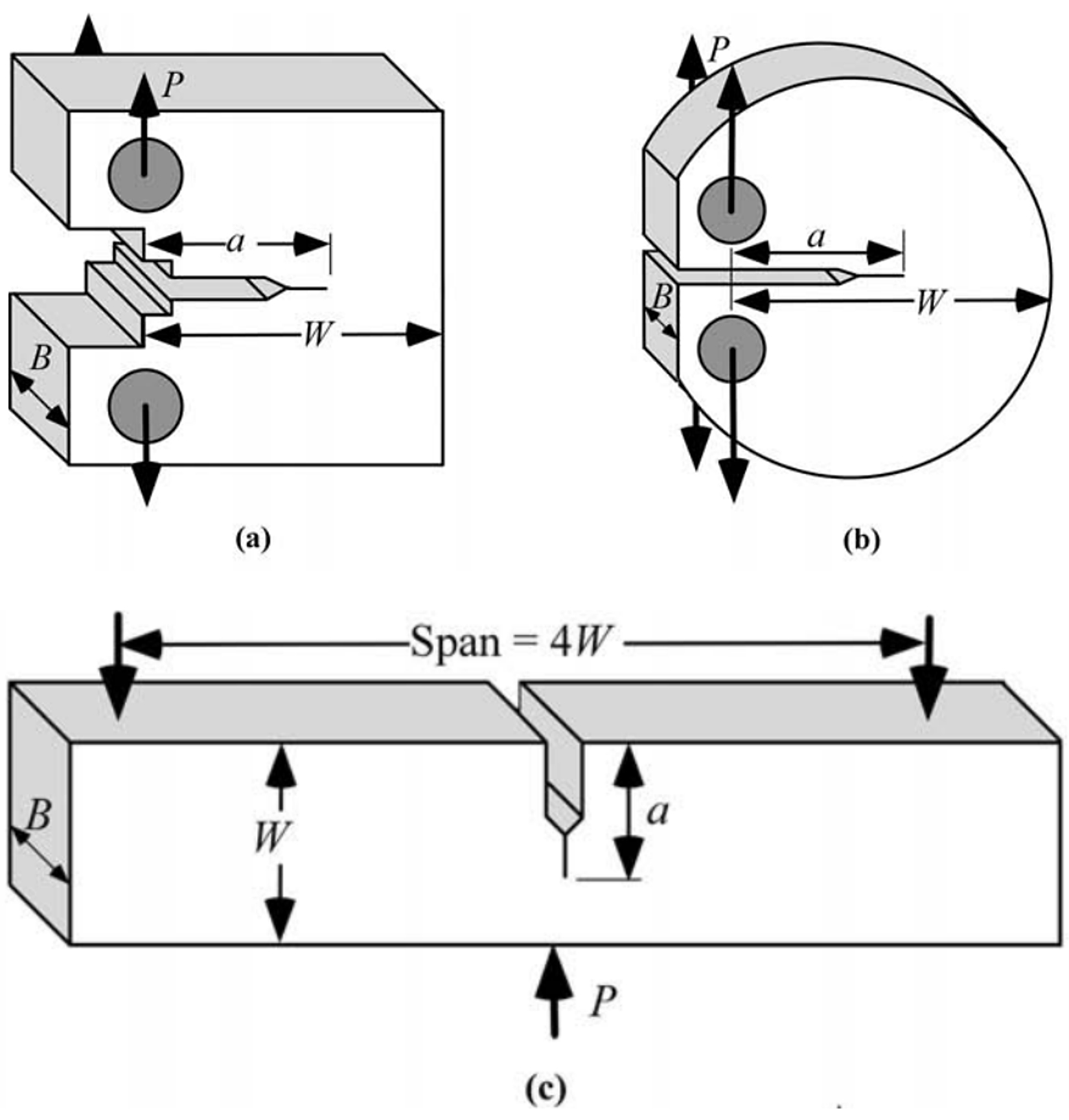
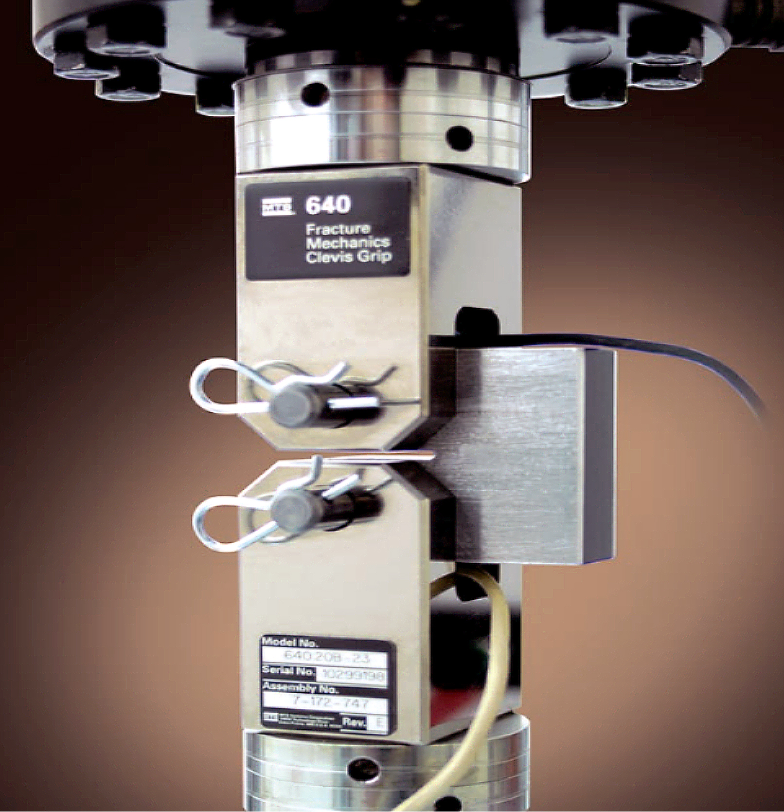
To conduct a fracture testing, one must select a specimen, introduce a crack in the specimen, get a test machine and instrumentation, test to failure and get failure data, relate failure data to a critical K, then repeat the test for a range of temperatures. There is a variety of test specimens. Standard ones are compact — C(T), disk-shaped compact, and single edge bend — SE(B), (Figure 1). There are other special specimen geometries, such as arc-shaped tensile — A(T), middle tension (MT), and arc-shaped bend — A(B). Specimen geometry can be decided based on the dimensions of available material. Typically, SE(B) is preferred for a sample with weldment, C(T) for plates and slabs, and disk-shaped compact is preferred for rods. The SE(B) can use simplified single fixture, while other dimensions will need specialized fixture per specimen dimensions. Special clevises are used to pin load compact specimen, (Figure 2). Specimen dimensions are scaled geometrically — a 1T sample has a thickness of one inch and a width of two inches. Regardless of specimen geometry, they all have three characteristics: crack length (a) along with thickness (B) and width (W). For most setup, width is twice the thickness and the ratio of crack length to width is approximately 0.5.
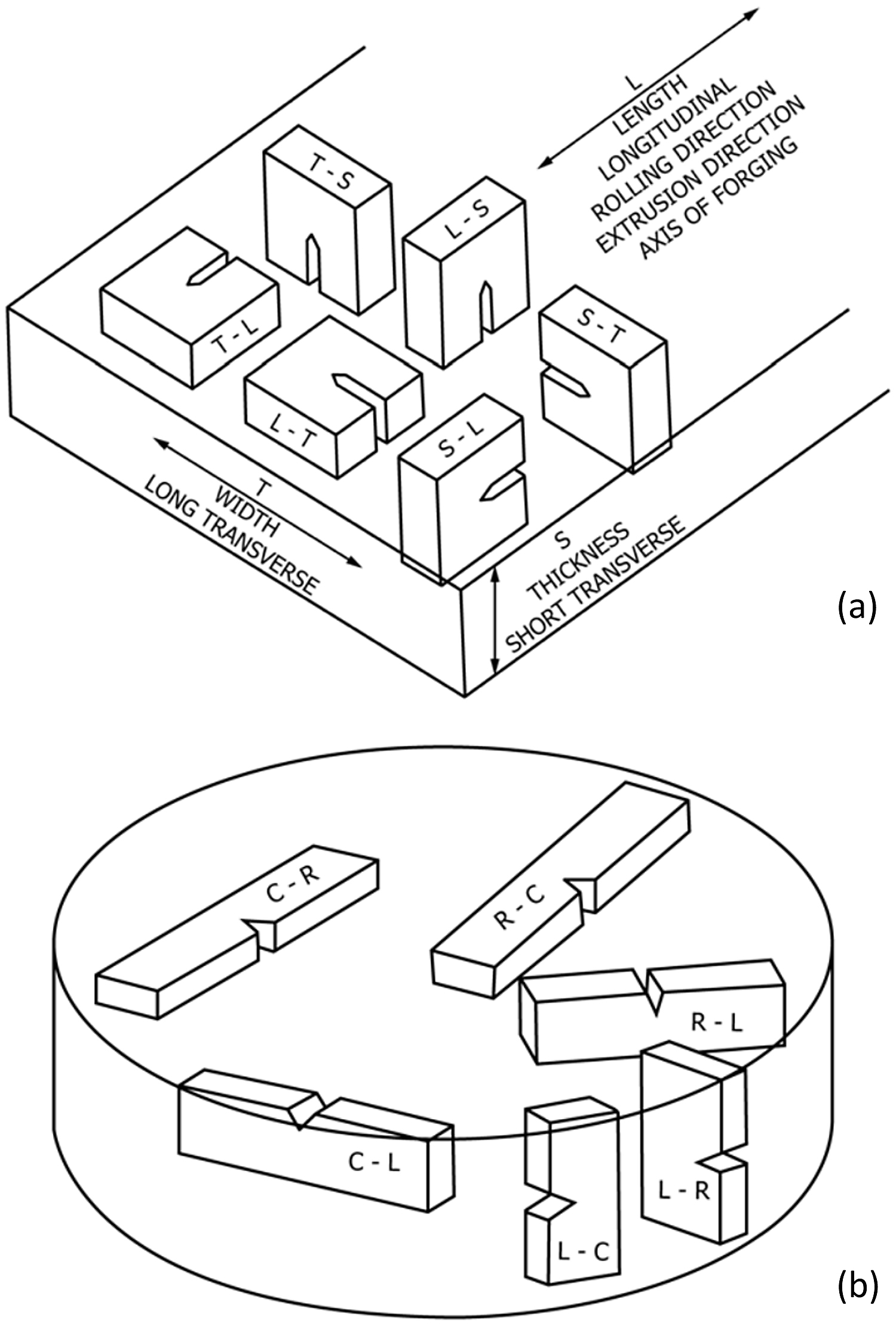
Due to texture in materials and their difference in strength relative to their orientation, crack orientation must be specified. Fracture toughness is sensitive to microstructure and prior materials processing. Certain crystallographic planes are more prone to crack propagation, while certain processing can alter microstructure to arrest crack and define plastic zone. Similarly, certain orientations are more prone for defect formation, coalesce, and growth. Thus, all specimen orientation must be identified while reporting material toughness. Specimen orientation used by ASTM is shown in Figure 3. Two letters are required to identify the orientation of fracture mechanics samples. The first letter denotes the principle tensile stress perpendicular to the crack plane for Mode I test. The second letter indicates the plane of crack propagation. Letters L, T, and S signify longitudinal, transverse, and short transverse orientation, respectively. Similar convention is used for cylindrical structure, where C, R, and L are identified as circumferential, radial, and longitudinal, respectively.
Precracking and cyclic loading in servo-hydraulic frames are done in load control. The load cell must be calibrated and have analog-to-digital conversion. The crack thus produced must be sufficiently sharp, which is an attempt to mimic defects present in a material. Fixturing must be designed for good mechanical performance based on specimen geometry. Servo-hydraulic test frames are best suited for these tests as it has better control, and it can generate variety of loading wave forms. The crack thus produced must have a small plastic zone at the tip compared to facture plastic zone and the tip radius must be smaller than the radius at failure. One must be considerate of maximum K during fatigue loading while introducing initial crack. The max K differs where the intended toughness is KIC for linear-elastic, or J or CTOD for elastic-plastic mechanics. Along with load, displacement or crack growth is measured during the test. A variety of displacement gages can be used, such as mechanical, clip gage, linear variable differential transformer (LVDT), laser, and capacitance.
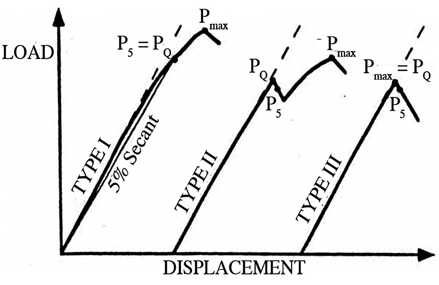
Heating or cooling is performed in a furnace or cold box. Soak times are dependent on specimen thickness; the rule of thumb is 30 minutes/inch. Temperature should be controlled to ± 3°C. The test, monotonic loading, is done in displacement or crosshead traverse control with controlled rate while measuring load and displacement. Measurements are done digitally by computer. Load rate must be between 30 – 150 ksi.in1/2/min — slow enough to avoid dynamic effects and fast enough to avoid time dependent effects. Continue loading specimen until the specimen fractures or a maximum load is passed. Three types of load-displacement behavior in a KIC test are shown in Figure 4. Identify the highest load up to a 5 percent secant crossing (PQ) and the highest load (PMax). Initial crack length (ao) is measured at three evenly spaced locations, then apparent fracture toughness (KQ) and PQ are calculated. Subsequently, KQ is calculated per Equation I. The f(a/W) is a dimensionless function whose individual values for material and temperature can be found in relevant ASTM specification, and in the U.S. Air Force Material Command’s Damage Tolerant Design Handbook [5]. It can also be calculated per Equation II for C(T) samples.
Due to the sensitivity of KIC to crack size, specimen thickness, relative plastic zone at crack tip, possible technician error, instrumentation malfunction, ASTM E399 requires a validity check to ensure confidence of the measured value. The test results must go through three validity check criteria: (i) crack size to specimen width ratio must be ≥ 0.45 and ≤ 0.55, (ii) Pmax ≤ 1.10 PQ, and (iii) a, B ≥ 2.5(KQ/σ YS)2. If validity checks are satisfied, KQ = KIC. However, at the end of the day, if KIC test is invalid, a stress ratio (RS) can be calculated to see extend of invalidity. RS is the nominal stress at crack tip divided by the yield strength. In a compact specimen, RS less than 1.0 indicates linear-elasticity, greater than 2.0 indicates fully plastic behavior, and in between 1.0 and 2.0 indicates nearly elastic to nearly fully plastic behavior. Though invalid, test results are still beneficial in material selection, design considerations and property comparison.
 Equation I
 Equation II [6]
Test Failings
Fracture toughness measurement is orientation specific, so it requires materials testing in mutiple directions, which can be costly. For certain forms of materials, it is impossible to obtain compact sample design in all orientations, especially for plates and welded structures; thus, test engineers prioritize orientation that is considered the weakest. The ASTM E399-based KIC is Mode I loading plane strain condition where crack tip plastic zone is relatively small compared to specimen thickness. Its applicability is limited to linear-elastic materials with limited ductility. As such, the technique is not applicable for many engineering materials that show plasticity, such as low-strength structural materials. With few exceptions, all engineering materials are selected with a certain degree of plasticity. Due to strict specimen dimension of requirement per ASTM E399, some test specimens can be impractically large and cannot be tested. Say we have a tool steel with KQ of 140 ksi and yield strength of 22 ksi — per one of the validity criteria, crack length has to be 81 inches and width of 162 inches. That is a very large dimension for a valid KIC test. For some materials, valid KIC tests are only applicable at room temperature or lower temperature where materials do not fail with void formation and coalesence. Side grooving can be done after precracking to remove areas of low triaxiality on the surface and to produce relatively straight crack plane but is not allowed per E399.
For nonlinear materials with larger plastic zone, plasticity corrections are made and toughness is measured per ASTM E1820 and British Standard 7448.
Reference
- G. E. Dieter, “Mechanical Metallurgy,” 3rd ed. McGraw Hill, Illinois, 1986.
- ASTM E399 – 22, “Standard Test Method for Linear-Elastic Plane-Strain Fracture Toughness of Metallic Materials,” ASTM International, West Conshohocken, PA, 2022.
- T. L. Anderson, “Fracture Mechanics – Fundamentals and Applications,” 3rd ed., Taylor & Francis, New York, 2005.
- MTS. (2022). MTS Series 640 Fracture Mechanics Clevis Grips.
- D.A. Skinn, J.P. Gallagher, A.P. Berens, P.D. Huber, and J. Smith, “Damage Tolerant Design Handbook,” University of Dayton Research Institute, OH, 1994.
- R. E. Reed-Hill and R. Abbaschian, “Physical Metallurgy Principles” 3rd ed., PWS Publishing Co. Boston, 1994.


 general practice for CQI-9 and AMS2750E")


