


A couple of years ago, as I was finishing my graduate studies, I was lucky enough to participate in the Strong Bar competition put on by the ASM Heat Treat Society at the Heat Treat Show 2021. This competition challenges university students to design and execute a heat treatment of their choice on a provided steel bar, which then will be tested in bending at the heat treat conference that year. The group with the highest combined load and deflection is deemed the winner.
This competition opened the possibility for my teammate and me to work in the university’s materials lab which was otherwise closed off to non-PhD students. We were able to perform metallurgical analysis such as sectioning, polishing, performing the micro-hardness traverse, and even etching the sample to see the microstructure. As a budding mechanical engineer looking to pursue a career in a materials-dominated industry, this was an invaluable experience. Our team weighed the available options for heat treatment on the bar and assumed our fellow competitors would be going for quench and temper processes to ensure their bars would be able to handle the bending load. Wanting a more novel heat treatment, our team decided on carburization to take advantage of the higher strength from adding carbon to the steel, as well as leveraging the residual surface compressive stress induced by the process. Unfortunately, this led to a more brittle microstructure and our bar failed spectacularly in the three-point bend machine on the conference floor. Regardless, much was learned, and it was a great experience overall.
After the competition, we received the broken sample and attempted to determine the mode of failure. Classically, bending stress is given by the equation:
![]() where sigma is the bending stress, M is the bending moment, c is the distance from the neutral axis, and I is the moment of inertia which handles the geometry effect on bending; shown schematically in Figure 1.
where sigma is the bending stress, M is the bending moment, c is the distance from the neutral axis, and I is the moment of inertia which handles the geometry effect on bending; shown schematically in Figure 1.
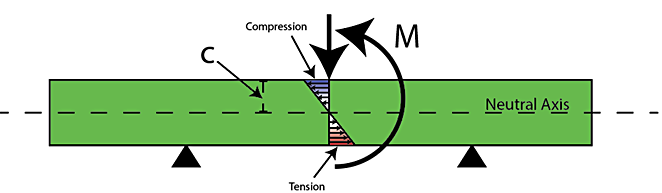
From the equation and Figure 1, we can see that the greater the distance from the neutral axis, the greater the magnitude of bending stress that point experiences. A hand calculation was performed using the data from the bend test, shear and bending moment diagrams learned from the previous coursework, and the bending stress equation previously described. The hand calculation returned a maximum tensile stress of 2333 MPa, which is more than three times the reported yield of 4140, and an FEA model was executed to view and analyze the non-linear behavior from bending.
Study
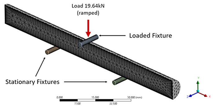
A finite element model was developed to simulate the three-point bending experiment that was performed for the competition. Taking advantage of symmetry, the 100 mm long, 9.5 mm diameter bar was halved axially and meshed with 24,858 elements and 13,876 nodes. A fine layer of elements near the surface was used to capture the carbon case and thermal gradients present in the heat-treatment model. Two cylinders were used on the bottom of the sample for the simple supports of the bending rig, while a third was used on top to apply the load, as shown in Figure 2.
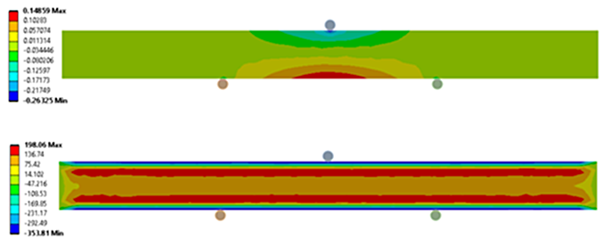
Having more carbon in the case delays the martensitic transformation during quenching, causing the carburized case to transform after the core. This delayed transformation induces compression in the case from the volumetric expansion of the austenite (FCC) to martensite (BCT) solid-state phase transformation. Figure 3 shows the model setup as the load is being applied for the noncarburized (top) and carburized (bottom) bending models.
Residual stress must be balanced in a part, meaning if compression resides in the case, there must be tension to off-set the compression. From Figure 3, there exists a layer of tension just under the carburized case. With a carburized sample, the magnitude of tension induced by bending is offset by the magnitude of near-surface residual compression developed during the carburization process. Likewise, the residual tension under the case increases the magnitude of tension from bending. Both factors combine to show that the maximum tension in the sample from bending is not necessarily at the surface as with the residual stress-free sample. Figure 4 shows the in-process bending stress for the residual stress free (top) and the stressed model (bottom).
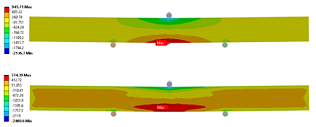
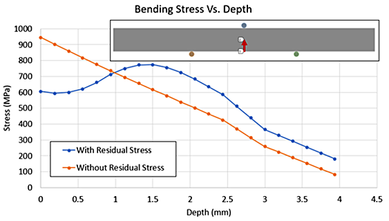
Figure 5 shows the plot of a path from the bottom of the sample to the core, at the same time-step as the contours in Figure 4, showing the difference in bending stress when including residual stress from heat treatment. The residual stress-free model shows an almost linear relationship between the distance from the neutral axis and the bending stress. The model with residual stress from heat treatment shows a lower bending stress in the case compared to the residual stress-free model. The reduced bending stress persists up to 1 millimeter from the surface, at which point the tension under the case begins to add to the tension induced from bending. The peak bending stress occurs at the 1.5 mm total case depth that was achieved from the carburization process. This region, at or near the base carbon level, would be more ductile compared to the carbon case, and at the instant shown in Figure 4 the magnitude of tension is just above the reported yield strength of AISI 4140.
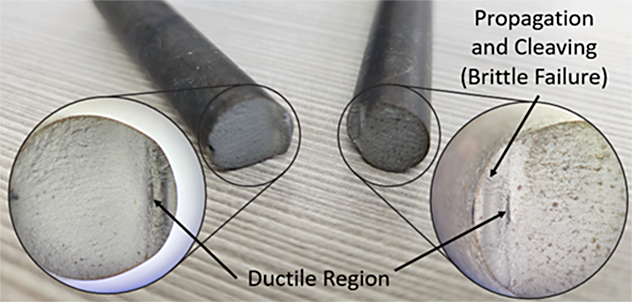
When inspecting the returned sample, shown in Figure 6, it is clear that there is a more ductile region at about 1.5 mm from the surface. From the edges of this ductile patch, cracks can be seen propagating toward the surface and the cleavage along this direction is indicative of brittle failure. The rest of the sample displays these signs of catastrophic brittle failure, showing that when the cracks did form and propagate the rest of the sample quickly followed.
Conclusions
In the three-point bend test, a sample experiences a moment from the load applied that imparts compressive and tensile stresses normal to the applied load. Typically, the highest magnitude of bending stress occurs at the surface, farthest from the neutral axis, but with a carburized part this is not always the case. After a failure at the Strong Bar competition, an FEA model was executed to explore the differences between a classic bending example and one using residual stresses from heat treatment. The models show that while the surface is farther away from the neutral axis, the peak tensile stress was just under the carbon case. Comparing the results of the model to the actual sample shows an agreement to the location of peak stress and the small ductile region under the case. From this ductile region, there exists several cracks leading to the surface which are most likely the cause of the spectacular failure on the exhibit floor. This work illustrates the importance of designing a case depth that is deep enough to handle the load applied. While parts in service will not typically be bent to failure, understanding the depth and magnitude of applied stress will ensure long and safe life of components. Once the part begins to yield all bets are off, so to speak, when it comes to the beneficial residual stress from heat treatment. Overall, I would advise any student who is interested in materials and heat treatment to participate in the Strong Bar competition. It was an invaluable experience to work in the metallographic lab, design and execute the heat treatment, and learn the lessons from failure in bending.


 general practice for CQI-9 and AMS2750E")


