


The final step in any steel heat-treatment quenching process which produces a martensitic microstructure is tempering. Martensite is a metastable phase and is extremely brittle due to the trapping of carbon as an interstitial solute. The trapped carbon atoms contort a body-centered cubic (BCC) crystal structure into a body-centered tetragonal (BCT) structure [1]. Martensite must be tempered before the component can be placed into service or there is a risk of premature failure. Raising the temperature of the martensite causes the material to seek an equilibrium state by ejecting carbon from the BCT structure, which will form carbides with other alloy elements and relax the BCT structure back to a BCC structure. Depending on the alloy content, different temperature ranges create different carbides and different properties, but generally, an increase in tempering temperature reduces the hardness and strength but increases ductility. Tool, and other high alloy steels go against this trend, gaining hardness and strength at higher tempering temperature ranges [2].
Tempering of steels has traditionally been conducted in furnaces, requiring many hours to complete a cycle due to the relatively slow heating rate. With induction hardening becoming a popular choice in industry, the use of induction for tempering seems like a logical choice to decrease processing time. However, unlike furnace heating, which produces a uniform temperature in the part once thermal equilibrium is achieved, induction heating produces a temperature gradient through the cross-section of a part. This is due to the Joule heating gradient induced by the induction coil. This temperature gradient created by induction heating is acceptable, even preferable, for quenching operations since it helps develop surface compressive stresses by only transforming the near surface to austenite. However, a temperature gradient during tempering means a gradient in hardness, strength, and ductility since the part is effectively tempered at different temperatures. Figure 1 shows the predicted temperature profile, in Celsius, of a 50 mm (2-inch) bar tempered at 200°C (395°F) using induction heating; actual temperature profiles will vary depending on the frequency and power used. The heat-treatment simulation software DANTE was used for the simulation and, for this particular case, it was assumed the Joule heating penetrated to a depth of 3.6 mm (0.142-inch).

Heating using induction created a 40°C (77°F) difference in temperature between the surface and core of the cylinder, as shown in Figure 1, with 200°C only being reached at one point at mid-radius. This gradient will create a softer, more ductile surface than the core, possibly leading to in-service performance issues. In an effort to reduce the temperature gradient during induction tempering, DANTE was used to explore the possibility of simultaneously heating with induction and quenching. Using the same depth of heating (frequency), but with an increase to the power applied to achieve the desired tempering temperature, and a quench rate commonly associated with spray quench systems used for induction hardening, a DANTE model was executed to evaluate the temperature uniformity. Figure 2 shows the resulting temperature profile, in Celsius, for this simulation. While there is still a 40°C (71°F) gradient, it is over a much smaller distance and it is inverse to the induction heated only part. This reversal of gradient can be preferable, as it will keep the surface slightly harder and stronger than the core.

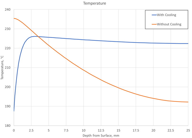
The temperature gradient can be visualized much better as a line plot. Figure 3 shows the temperature profile from the surface to the core for both tempering conditions. As can be seen, the temperature is effectively uniform for the condition which simultaneously heated and cooled at a depth greater than 2 mm (0.079-inch). This is not the case for the component which was only heated; a uniform temperature is never achieved through the cross-section. The lack of nonuniformity means that compromises must be made as to the target tempering temperature, since the chosen temperature will only exist at one point within the part.
The final goal of any tempering process, from the view of the heat treater, is to achieve a given hardness at a given location. For induction tempering processes, a surface hardness measurement does not tell the entire story; since hardness is a strong function of temperature, a temperature gradient will lead to a hardness gradient. Figure 4 shows the hardness profiles for the two tempering conditions. Although the temperature gradient magnitudes are similar, the hardness is much more varied in the heating only case, with six HRC points separating the surface and the core. The simultaneously heated and cooled condition only has a difference of two HRC points. This small difference only exists over a small distance from the surface, whereas the heated only condition has the highest hardness in the core and the lowest at the surface. A surface which is softer than its core may pose problems in service with respect to fatigue performance.
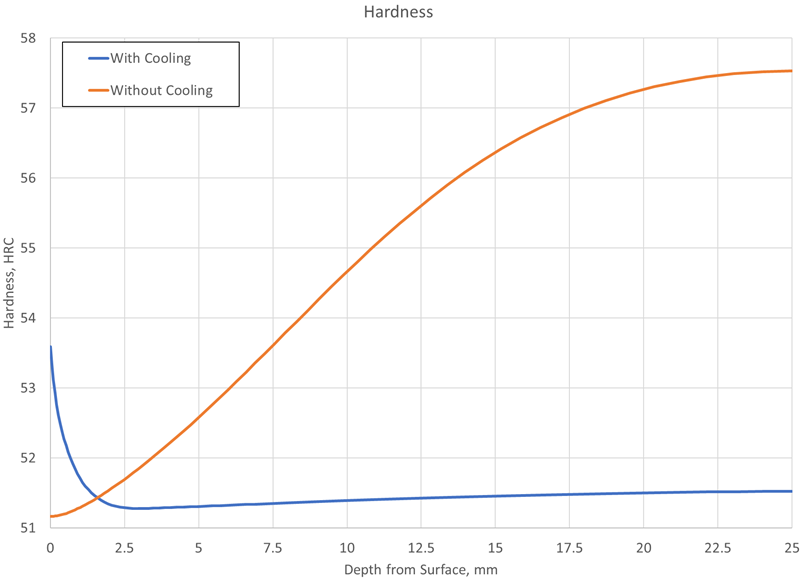
In conclusion, the temperature uniformity of an induction tempered component can be significantly improved if the component is simultaneously cooled while being heated with the induction coil. DANTE modeling was used to show that although the magnitude of the temperature gradient is approximately the same between the two processes, they are inverse to each other. The cooled and heated condition creates the gradient over a small distance near the surface, whereas the heated only condition spreads the gradient out over the entire cross-sectional thickness. The differences in the two gradients are reflected in the hardness profiles; the cooled and heated condition produces a nearly uniform hardness profile, except for a slight increase near the surface. This is in contrast to the heated only condition, which produces a large hardness difference between the surface and the core, with the core being harder than the surface. This difference can have detrimental effects on fatigue performance. Heat-treatment simulation software, such as DANTE, can be used to optimize the process with respect to temperature uniformity by determining the appropriate frequency, power, and quench rate. Once optimized using simulation, induction tempering using simultaneous cooling can be an excellent choice to replace time intensive furnace tempering operations.
References
- Hubertus Colpaert, Metallography of Steels; Interpretation of Structure and the effects of Processing, ASM, 2018, p 202 – 204.
- Hubertus Colpaert, Metallography of Steels; Interpretation of Structure and the effects of Processing, ASM, 2018, p 321-325.


 general practice for CQI-9 and AMS2750E")


