More gear manufacturers need to add vacuum furnace machines to the shop floor and include this procedure in the overall manufacturing process. As vacuum furnaces are added, many maintenance issues arise. This article covers many aspects to ensure the quality output of these machines.
Safety
As with any piece of equipment, proper maintenance at regular intervals is essential for long service life and trouble free operation.
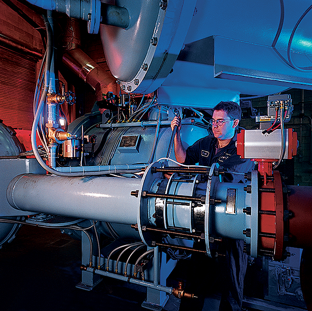
The mechanical components in a vacuum furnace require standard maintenance practices, including cleaning and lubrication. However, successful use of a vacuum furnace depends on the purity and reliability of its vacuum. Additional maintenance activities are required to ensure good vacuum levels in the system. Leaks in joints and contamination of furnace internals will greatly affect operating vacuum levels and the quality of the processing. Leaks are the most time-consuming and troublesome of the maintenance items. Small leaks can only be isolated using helium leak detectors. However, by keeping track of where leaks most frequently occur, preventative measures can be taken to minimize the problem. The operating manuals supplied with VAC AERO furnaces provide detailed information on maintenance and trouble shooting. All maintenance manuals should be read and understood before commencing furnace operation.
There are a number of safety issues that must be considered when maintaining vacuum furnaces. Standard safety practices must be adhered to in order to avoid injury, burns and electrocution. In addition to these, there are several special considerations specific to vacuum furnace equipment. On furnaces equipped with oil diffusion pumps, maintenance should only be attempted after the pump has been allowed to cool to ambient temperature. The diffusion pump works by boiling oil to form a vapor. Heated by coils in the base of the pump, oil temperatures reach 240ºC (464ºF) and higher. At these temperatures, vapors from hydrocarbon-based oils can react explosively with air. As a result, the fill port in the pump should never be opened while the pump is operating. Silicone-based pump oils eliminate this explosive risk.
Maintenance of furnace chamber internals should only be conducted using approved confined space entry and electrical lockout procedures. Residual quench gases remaining in the tank even after the door is opened can cause asphyxiation. Particular care should be taken when entering furnace chambers after argon has been used as a quench gas. Argon is heavier than air and can remain in low-lying areas for some time. It has no discernable odor and there is usually no advanced warning before unconsciousness occurs. Vacuum conditions in a furnace tank are even more lethal. Lockout procedures to prevent furnace operation must be in place before entering any furnace chamber.
Vacuum Seals
During construction, all welded joints in a vacuum furnace are inspected for hermetic integrity and should remain intact for the life of the furnace.
However, there are also a number of demountable connections that can be separated and reconnected for component changing or repair access reasons. These connections are generally sealed with a gasket sandwiched between two flanges. Though different gasket materials are used depending on the vacuum level required most seals in a standard vacuum furnace incorporate an o-ring made of natural or synthetic rubber. Buna-N, silicone and Viton o-rings are readily available in many sizes.
These materials are resilient and can be used repeatedly without loss of integrity. The common squish rates of 20 percent to 50 percent of the original cross section will not stress o-ring materials past their elastic limits. O-rings must be properly retained within the connection to prevent being sucked into the vacuum system. Usually, they are set in a groove machined into a flange on one side of the connection. They are then squeezed against the opposite flange as the flanges are tightened together. A less common method of o-ring retention involves a retaining ring that is thinner than the o-ring cross section. The retaining ring fits inside the inner diameter of the o-ring.
 The surface finish on the flanges where the o-ring is squeezed should be no more than 125 RMS. A coarser finish may result in gas penetrating through the seal. Flange faces should be inspected for burrs or scratches prior to assembly. The standard practice is to coat the o-ring with a thin layer of vacuum sealing grease prior to assembly to improve its sealing properties. A common cause of leakage in o-ring sealed joints arises from damage to the o-ring. O-rings should never be removed from grooves using sharp objects, such as screwdrivers or knives. Not only can these objects cut the o-ring, they may also cause scratches in the bottom of the o-ring groove, which will provide another path for gas penetration. O-rings should be regularly inspected for damage and cleaned of all dirt and particulate matter.
Because of frequent opening and closing, door o-rings are most susceptible to damage and should be inspected prior to every run. They should be checked for nicks, cuts or flat spots. Both o-ring and door flanges should be wiped clean before the door is closed. Re-coating of the o-ring with a thin layer of vacuum grease should be performed at regular intervals though any build up of vacuum grease must be avoided. Improperly assembled feed-thru seals may also be a source for leaks. When changing control or over-temperature safety thermocouples, feed-thru seals must be properly tightened to ensure vacuum integrity. Small leaks may be temporarily overcome by applying a sealing compound on external surfaces of the vacuum joint. However, this not a permanent corrective measure.
Minimizing Out-Gassing
Whenever the door to a vacuum furnace chamber is open, humidity from the air will enter the chamber and condense in a very thin film on the chamber walls or be absorbed into the hot zone materials.
When the chamber is subsequently evacuated (before heating) and the furnace internals are exposed to this lower pressure, “out-gassing” of the entrapped moisture will occur. If sufficient moisture has been entrapped (such as in very humid environments), the out-gassing effect will slow the pump-down process and may even give the appearance of a malfunction in the pumping system. Eventually, the out-gassed moisture will be pulled out of the chamber by the pumping system and evacuation rates will improve. This same effect will be apparent when oily or contaminated workloads are placed in the furnace. It may be more pronounced in furnaces with graphite-based hot zone insulation materials.
To minimize the out-gassing effect, it is important to keep the chamber door closed whenever possible. Ideally, the chamber should also be kept at least partially evacuated whenever the furnace is not in use. It is also important to maintain the recommended temperature of the coolant entering the cooling jacket. Condensation of moisture is more pronounced on cooler surfaces.
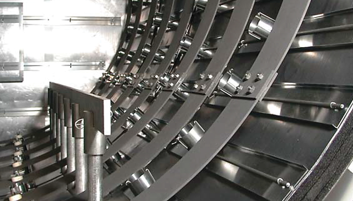
 In addition to problems created by moisture, vaporization of volatile elements when heated under vacuum will eventually contaminate the furnace internals with undesirable residues. The evolution of this condition may become apparent by deteriorating ultimate vacuum levels. Deposits of metallic residues can also cause electrical short circuits. Often, however, considerable amounts of contaminants can be present with no discernable change in operating pressures. Regular dry run cycles must be performed to burn off contaminants before they begin affecting load quality or create electrical problems.
The furnace maintenance manual will provide detailed instructions for performing a dry run cycle. As a minimum, at least one dry run cycle should be performed each week. Depending on the cleanliness of the work processed previously, a dry run cycle may also be required immediately prior to processing a critical workload or materials that are particularly prone to contamination such as titanium alloys.
Leak Rate Testing
The vacuum level as indicated by vacuum gauge readings is not always a true indication of the actual conditions within a vacuum furnace.
It is possible to have two identical furnaces operating at the same pressure but producing entirely different results on heat-treating. This can be explained by the relative leak tightness or leak rate of each furnace. Most furnaces are equipped with pumping systems sufficient to overcome reasonably significant leaks. On the furnace with the higher leak rate, air would be leaking continuously into the furnace resulting in higher residual oxygen content than in the leak-tight furnace. The higher oxygen content would adversely affect the heat-treating results. Therefore, leak rate checks as prescribed by the furnace manufacturer should be performed at regular intervals to prevent this problem.
To ensure that the processing environment is not being contaminated by impurities leaking into the furnace, the relative leak tightness of the furnace needs to be regularly tested. Every leak rate test should be preceded by a high temperature dry run (bake out) of the furnace. In the dry run, the empty furnace is usually heated to a temperature at least 55ºC (100ºF) above the its normal operating temperature, then allowed to cool under vacuum. For most general heat-treating furnaces, a dry run temperature of at least 1200ºC (2200ºF) should be used. The furnace should be held at this temperature for at least 30 minutes but not longer than 60 minutes. The purpose of the dry run is to bake out any residual moisture or other impurities accumulated from lower temperature processing.
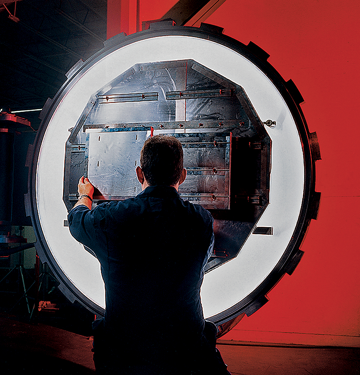 The leak rate test is performed immediately after the dry run cycle without venting the furnace to atmosphere. First, the pumping system is started in the manual mode and the furnace is pumped down to 1 x 10⁻⁴ torr or better. The pumping system is then isolated from the furnace chamber. The vacuum level is recorded after 30 minutes and again after 60 minutes. The leak rate can then be calculated in microns per hour and compared to the acceptance criteria in governing specifications.
Newer furnaces should not have leak rates exceeding 10 microns per hour at a pressure of 70 microns or less. For older furnaces, leak rates of 20 to 25 microns per hour are not unusual. These leak rates ensure that the volume of impurities that may be leaking into the furnace is sufficiently low so as not to cause any significant detrimental effects to the materials being processed.
A furnace exhibiting a leak rate greater than these limits should not be used for production until repair of the leak. In this case, the normal procedure is to backfill the furnace with nitrogen, but do not open the chamber to atmosphere. All thermocouple fittings and other vacuum feed-thru should be tightened. The furnace can then be re-tested for leak rate as before. Failure of the second leak rate test is an indication that the furnace requires more extensive maintenance, possibly including helium leak checking.
A comprehensive preventive maintenance program is essential to minimizing downtime due to vacuum leaks. Proper care of pumps, O-rings and flange sealing surfaces and regular inspection of vacuum feed-thru can help prevent leaks. Continuous monitoring of vacuum levels during processing can also help to identify potential problems before they develop into major repairs.
This article was provided by VAC AERO International, Inc. Please contact Alan Charky, marketing and communications director of VAC AERO at vacaeromarketing@vacaero.com or visit www.vacaero.com/informationresources.html for more information.
Challenges of vacuum processing
Temperature control in a vacuum heat treating environment can be difficult because of the changing heat transfer characteristics of the furnace as it moves from conduction and convection to radiation. The rapid heating rate of a vacuum furnace demands precise control, including setpoint program control with soak guarantee inputs.
Overshoot of temperature set points is usually not tolerated for metal treating applications.
Setpoint program control is often applied to both the temperature and the vacuum, with extensive interaction between the two programs and also with the logic control.
Vacuum furnaces are often used by a variety of products by the heat treater making recipe management an important function.
Vacuum furnaces are used in the metal treating industry for applications such as heat treating, brazing, melting, thin film deposition, etc. They are used to bring materials to high temperature with a minimum of surface reaction such as oxidation. In addition, surface and internal contaminants on molten metal applications are volatized and removed. Heating is fast and efficient using radiant energy that heats only the product in the vacuum environment.
Vacuum furnaces for heat treating and brazing are typically single chamber furnaces operating batch cycles. The batch cycles vary between processes but commonly require regulation of temperature, vacuum and sequence logic. The temperature and vacuum interact extensively with the logic.
A typical heat treating cycle starts after the product is loaded into the furnace and the door is clamped shut. Some users secure the furnace and perform a leak test before proceeding. A roughing vacuum pump lowers the pressure to about 50 microns. A diffusion pump lowers the pressure to below 1 micron. Some processes require an inert gas such as argon to be fed into the furnace at a low rate, allowing the pressure to rise to about 500 microns (this process is called partial pressure (PP) heat treatment).
The pressure increases as the temperature rises and contaminants volatize. Control of the vacuum is maintained at about 500 microns in PP processes or below 10-4 TORR in high vacuum processes. If the vacuum deviates from the specific set point by more than a specific value, the temperature program is held until the condition is corrected. The temperature program goes through a series of ramps and soaks. After a high temperature soak, the furnace is bottled up and the temperature is allowed to drop. An increased flow of inert gas and circulation of cooling water in the furnace walls cools the work. The cooling lowers furnace pressure, requiring additional pressure control. During the cooling, the pressure is controlled between 0.85 Barr to 10 Barr depending on process type. A light or horn usually provides indication to the operator that the cycle is complete. The operator brings the furnace back to atmospheric pressure manually and unloads the product.


