


Quench hardening of steel components involves complex, nonintuitive phenomena, particularly as it relates to the dimensional changes and stresses induced. Figure 1 shows a dilatometry curve for AISI 9310 steel alloy, with a 10°C/sec heating rate and a 20°C/sec cooling rate. Quench hardening of a steel component begins with the component at room temperature, with some initial microstructure; the structure is assumed to be pearlite in Figure 1 and room temperature is defined as 20°C. As thermal energy is supplied to the component, the material expands linearly with respect to the temperature change. This expansion continues until enough energy has been supplied that the steel undergoes a solid-state phase change, transforming from a ferritic, body-centered cubic structure (BCC structure) to an austenitic, face-centered cubic structure (FCC structure). This atomic rearrangement increases the density and reduces the overall dimension of the component; this can be seen at the “Austenite Transformation” in Figure 1. After completing the austenite transformation, the component continues to expand until thermal equilibrium is achieved.
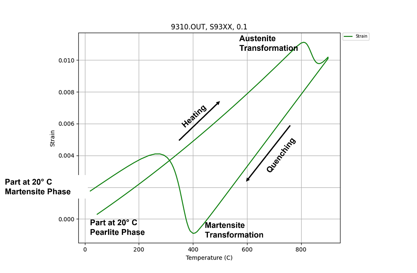
Quenching is the rapid removal of thermal energy from the part by some fluid. As the component is cooled, its overall dimension is reduced, though at a different rate compared to the initial structure, as seen in Figure 1. This is due to the difference in the coefficient of thermal expansion between an FCC and BCC structure. All transformation products at room temperature will be a ferritic structure (BCC structure) with varying carbide forms. The exception is as-quenched martensite, which is a BCC structure super-saturated with carbon. The trapped carbon contorts the BCC structure into a body-centered tetragonal structure (BCT structure). However, upon tempering, the crystal lattice is relaxed back to a BCC structure with fine, spherical carbides.
Although there are several phases which can be realized during quenching, all will increase the dimension of the component compared to the austenite phase, though to varying degrees since they occur at different temperatures. The change in density is the cause of distortion, which can be classified as size change and shape change. Size change is inevitable with the volumetric change of the phase transformation, but significant shape change distortion can occur if the phase transformations occur at different times locally within the component. For the example shown in Figure 1, the only phase obtained during quenching is martensite. The dimensional change as the material transforms to martensite is significant and is the cause of most stresses generated during quenching and then those remaining at room temperature as residual stress. This large change in strain can be seen at the “Martensite Transformation” in Figure 1.
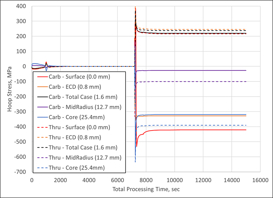
To see how this dimensional change correlates to the in-process and residual stress, the heat-treatment simulation software DANTE was used to model a 50.8 mm sphere, made of AISI 9310, and subjected to a quench hardening process. A sphere was chosen for this study to negate any geometry related effects on stress and strain. Additionally, two different scenarios are evaluated: carburized to an effective case depth (ECD) of 0.8 mm and thru-hardened. Figure 2 shows the hoop stress in the sphere as a function of total processing time for the entire hardening cycle for both cases; tempering was not modeled, though it can be and is expected to reduce the residual stress slightly. Stress histories are compared at the surface and at depths of 0.8, 1.6, 12.7, and 25.4 mm from the surface of the sphere for both cases. Depths of 0.8 and 1.6 mm represent the ECD and total carbon case in the carburized part, respectively. The mid-radius and core points are represented by the depths of 12.7 and 25.4 mm, respectively. The stresses generated during heating, and the subsequent austenite transformation are insignificant compared to the stresses generated during quenching. However, a component’s geometry can influence its dimensional response, so it should never be assumed that there will be no distortion or stress-related issues during heating.
To gain a better understanding of the stress evolution during quenching, Figure 3 plots the first 400 seconds of the quenching process for the surface, mid-radius, and core points. Interestingly, the core and mid-radius positions behave very similarly in the carburized and thru-hardened spheres. Quench hardening, with respect to in-process stresses, is a cyclic process. For the mid-radius location, a slight compression is first induced, followed by a spike in the tensile stress. As the process progresses, the mid-radius is again driven into compression, where it remains as a residual stress. The core position behaves in a similar fashion as the mid-radius, but with slightly larger magnitude of compression. The compression in the core of both cases is due to the fact that the core is the last area, far removed from the surface, to transform from austenite. Although the mid-radius and core positions are effectively the same, with respect to the stress evolution, the surface behavior differs between the two cases.
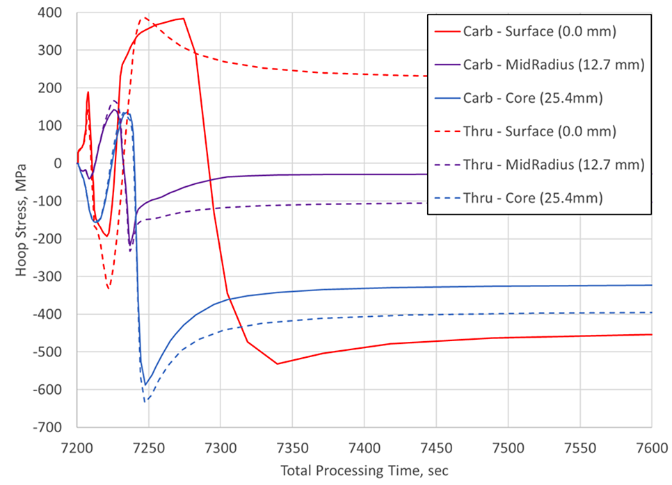
As shown in Figure 3, the surface of the thru-hardened case remains in tension, but the surface of the carburized case is driven into compression. This is a result of the transformation beginning at the case-core interface and progressing toward the core and the surface, simultaneously, as shown in Figure 4. The red band of martensite transformed first, and is spreading toward the core and the surface, though at different rates, as revealed by the thickness of the green band. The rate at which the transformation front progresses in either direction will depend on the alloy’s hardenability, the carbon gradient, and the cooling rate. However, unless influenced by geometric effects, the stress morphology for carburized components proceeds as shown in Figure 3.

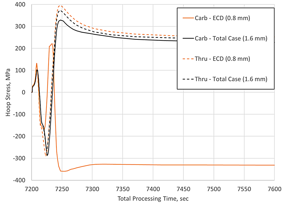
Figure 3 showed that the stress evolution between a carburized and thru-hardened component are effectively the same, though great differences exist at the surface. Figure 5 explores the stress morphology between the two cases at the distances from the surface defining the ECD and total carbon case depth (i.e., the case-core interface). The behavior at the total case depth, 1.6 mm in this example, is effectively the same between the two cases. However, the behavior at the ECD is significantly different. The carburized case has a high level of compression at this location, whereas the thru-hardened case is in tension. It should be noted that the material’s hardenability, the component’s geometry, the depth of carbon enrichment relative to the total cross-sectional thickness, and the cooling rates can all have a significant effect on the stress morphology. However, in the most general sense, compression will be realized at the surface, and through the carbon case, for a carburized part and residual tensile stress will generally be present at the surface of thru-hardened parts.
In conclusion, the quench hardening process of steel components can be a counter-intuitive process, as the thermal and phase transformation influence on dimensional change counteract one another. The heat-treatment simulation software can be used to explore this phenomenon and show that the volumetric change brought about by the solid-state phase transformation induces a tremendous amount of stress in the component, leading to residual stresses. It was also shown that carburized and thru-hardened components have significantly different stress histories at the surface and near surface locations, but effectively progress the same away from the carbon gradient.


 general practice for CQI-9 and AMS2750E")


