


Although carburizing is a complicated process, it can be broken down into two main steps: carbon generation in the furnace and carbon diffusion into the workpiece. The first step provides the source (carbon atoms) while the second determines the purpose (carbon concentration gradient and hardness profile) of the whole thermal process. Carbon generation was discussed in the Spring/Summer 2016 Metal Urgency column, so this paper focuses on the diffusion part of carburizing. Processing parameters including temperature and carbon potential based on diffusion theory are also discussed.
Generally, the goal of carburizing is to reach a designated case through which improved mechanical properties — such as surface hardness, tensile strength, and fatigue and wear resistance — as well as the preferred stress condition (compressive residual stress) on the surface can be reached after quenching and tempering. Historically, this case is called total case depth, which refers to the maximum depth of diffused carbon. Nowadays, effective case depth (ECD) is used to replace total case depth, as it can be practically defined and more consistently measured. Per the American Gear Manufacturers Association (AGMA), ECD is defined as the distance between the carburized surface to a location where the hardness number is 50 HRC (542 HK500 or 515 HV500) by conversion from a microhardness test result [1]. For plain carbon steels, this ECD corresponds to a depth where about 0.4 wt.% carbon content is contained and 50 HRC is measured.
Before discussing carburizing parameters, carbon diffusion in the steel should be analyzed.
Carbon Diffusion
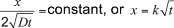
Disregarding interactions between carbon and other elements such as iron and alloying components (manganese, chromium, nickel, molybdenum, etc.), carbon diffusion within the workpiece can be described by Fick’s laws of diffusion. Because the diffusion flux and the concentration gradient near the surface vary with time due to accumulation of carbon, it is considered a nonsteady-state diffusion and can be expressed by Fick’s second law:
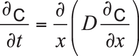 Equation 1
In the equation, C is the concentration of carbon, t is time, x is the position or depth below the surface of the part, and D is the diffusion coefficient.
For simplicity, if we ignore the dependence of D on carbon content, Equation 1 can be revised as:
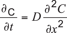 Equation 2
When some boundary cond itions are specified and assuming surface carbon concentration to be constant (i.e., equal to carbon potential), and the carburized part is thick enough compared with the case depth (typically, thickness of the part is larger than ![]() ), Equation 2 can be solved and expressed as:
), Equation 2 can be solved and expressed as:
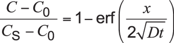 Equation 3
Here, C is the concentration at depth x after time t. Cs is the constant surface concentration at x = 0. Usually, this is equal to carbon potential. Expression is the Gaussian error function.
It can be seen from Equation 3, for specific carbon concentration C such as 0.40 wt.%, the left-hand side of Equation 3 is a constant. This implies the right-hand side is also a constant, therefore:
 Equation 4
K is the carburizing factor, and x (more commonly, effective case depth) is a parabolic function of carburizing time.
From Equation 3, it is concluded that carburized depth x or effective case depth (ECD) is a function of several parameters including carbon content of the steel, carbon potential, specified carbon content at 50 HRC, carbon diffusion coefficient, and time:
 Equation 5
Clearly, for a given steel and specified carbon content at 50 HRC, ECD is mainly determined by carbon potential, diffusion coefficient, and carburizing time.
Carburizing parameter selection
Diffusion theory indicates that the diffusion coefficient is determined by activation energy for diffusion and temperature:
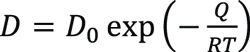 Equation 6
Where D0 is a temperature-independent pre-exponential (m2/s), Q is the activation energy for diffusion (J/mol), R is the gas constant, 8.314 J/mol·K, and T is the absolute temperature (K).
Specifically, for the diffusion coefficient of carbon in austenitic iron from 800°C to 1000°C, Reference [2] revealed:
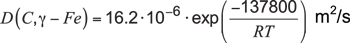 Equation 7
Temperature
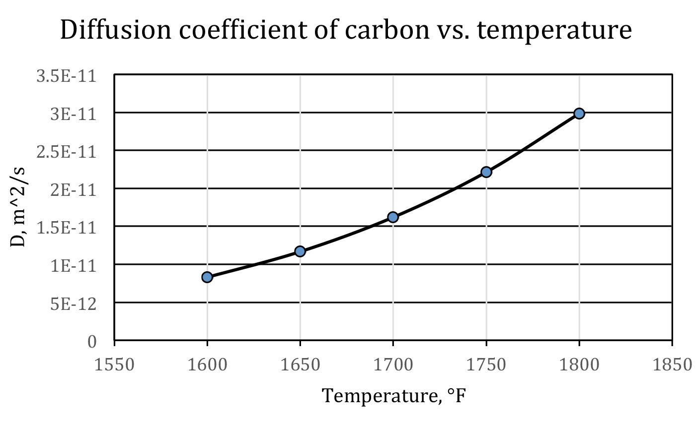
Equation 6 shows that temperature has a most profound influence on the diffusion coefficient — the higher the temperature, the faster the carbon diffuses. This is one of the reasons that carburizing is processed in an austenitic region. For plain carbon steels, this is above the Ac3 line on the iron-carbon phase diagram. As a rule of thumb, at normal carburizing temperatures, when temperature increases 100°F, the diffusion coefficient of carbon will roughly be doubled; when temperature increases 100°C, the diffusion coefficient of carbon will roughly be tripled. This is displayed in Figure 1.
Therefore, from a processing point of view, we should always try to set a high carburizing temperature as it will shorten the cycle time. On the other hand, this is restricted by manufacturing capability (the highest temperature the furnace can reach), cost, and maintenance. Furthermore, when temperature is too high, the grain growth will give rise to unexpected mechanical properties. Taking into all these considerations, the carburizing temperature is usually no higher than 1800°F (982°C).
Carbon Potential
Equation 3 shows that carbon potential facilitates carburizing. This is similar to temperature, although the effect of the former is not as remarkable as the latter. Correspondingly, we should set carbon potential as high as possible at a given carburizing temperature. However, this setting is limited by the maximum dissolved carbon content in austenite, i.e., the Acm line on the iron-carbon phase diagram at the carburizing temperature. When the limit is reached, a carbide network will be formed on the grain boundaries. Whenever this happens, the workpiece should be reworked, otherwise it will likely get cracked during the following manufacturing operation, such as grinding, or will fail prematurely during service. An example of a carbide network with an SAE 9310 steel is shown in Figure 2.
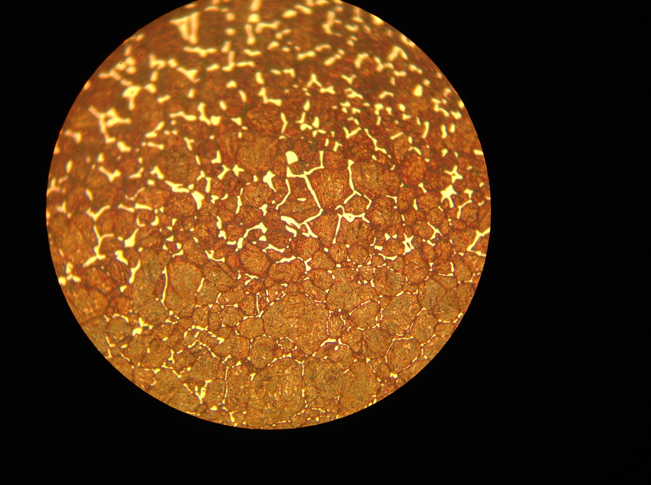
during carburizing
For most carburizing steels, the appropriate carbon potential is roughly 0.90 wt.% to 1.40 wt.% at 1600°F to 1800°F.
Based on Equation 3 or 5, once carburizing temperature and carbon potential are set for a specific steel, carburizing time can be determined to reach a designated effective case depth.
References
- AGMA 923-B05, p. 6.
- R.P. Smith, Acta Met., Vol 1, 1953, p. 578.


 general practice for CQI-9 and AMS2750E")


