


Thermal insulation composites are widely used in civil and military applications; however, it is difficult to achieve the synergy of multiple technical objectives such as lightweight, thermal insulation, high-pressure resistance, and high-temperature resistance by adopting traditional preparation techniques. In this study, a novel carbon-graphite thermal insulation material was rapidly prepared by exploiting the micro-thermal press additive manufacturing forming technology, and these multiple objectives were simultaneously achieved by introducing a large number of closed pores. It was found that the percentage of closed pores in the carbon-graphite insulation grew by increasing the forming density or the amount of thermosetting phenolic resin added, but the thermal conductivity increased in parallel with the compressive strength, while the addition of pre-covered expandable graphite was able to achieve the synergy of high-compressive strength and low-thermal conductivity. When the content of thermosetting phenolic resin was 25 wt%, forming density was 1.2 g·cm-3, and expandable graphite was clad twice, the prepared carbon-graphite insulation exhibited a closed porosity/porosity ratio, compressive strength, and thermal conductivity of 48.92%, 16.432 MPa, and 0.743 W·m-1 K-1, which has the advantages of lightweight, high compressive strength, heat insulation, and high-temperature resistance and has good prospects for industrial applications.
Introduction
In spacecraft thermal protection systems (TPSs), the connection between the external anti-insulation layer and internal cold structure of the airframe must be prepared using thermal insulation materials, which act as thermal insulation and load-bearing components [1,2,3]. The representative thermal insulation materials at present are porous fibers/ceramics, aerogels, carbon-carbon (C/C) composites, and carbon-graphite [4,5,6]. Wang et al. prepared a novel high-temperature vacuum insulation material consisting of a graphite felt core and a sealing layer via chemical infiltration (CVI), named pyrolytic carbon and impregnated silica sol. When the temperature increased from 500 to 1,200°C, the effective thermal conductivity reduced from 0.403 to 0.368 W·m-1 K-1. This material was applied in the TPS of launch vehicles [7]. Wu et al. prepared a high-density high-temperature insulation material, which exhibited a bulk density of 1.64 g·cm-3 and bending strength of 47.8 MPa after heat treatment at 2,100°C [8]. Carbon-graphite insulation materials (e.g. carbon felt and flexible graphite paper) are superior to other insulation materials in terms of their temperature resistance, oxidation resistance, production cost, and mechanical properties, yet remain inferior in terms of the thermal conductivity. Moreover, it remains challenging to achieve synergy between multiple functional objectives such as a low weight, thermal insulation, high-pressure resistance, and high-temperature resistance.
The introduction of closed pores in thermal insulation materials such as ceramics and carbon-graphite can effectively reduce their thermal conductivity while maintaining the mechanical properties. It was reported that a closed pore porosity of 14.5% can be attained by introducing microspheres with a content of 10%, and the thermal conductivity at 23°C can be reduced from 28.08 to 13.07 W·m-1 K-1 with a bending strength of 97.05 MPa [9]. Cheng et al. prepared porous mullite ceramics with a fully closed pore structure by direct solidification casting, using fly ash hollow spheres as the porogenic agent. The total porosity of this material ranged from 44.73-46.12%, with 99% of the pores being closed, and the compressive strength increased by 14.4% to 58.07 ± 5.44 MPa [10]. Moreover, the research group used selective laser sintering to rapidly prepare a low-density carbon-graphite/silicon carbide composite thermal insulation material and noted that a certain number of closed pores could be formed inside the material through the addition of expandable graphite (200 mesh, 1–1.5 wt%). This framework simultaneously exhibited a low thermal conductivity and high compressive strength, with values of 1.21 W·m-1 K-1 and 13.87 MPa, respectively [11].
In this article, a new type of carbon-graphite thermal insulation material was prepared based on the principle of micro-thermal compression additive manufacturing technology. The effects of forming density, the amount of thermosetting phenolic resin added, and the number of times of cladding pretreatment on the pore state, compressive strength, and thermal conductivity of the charcoal-graphite thermal insulation material were studied, and the conditions and mechanism of closed pore formation were revealed. The thermal conductivity model and mechanical model were obtained by comparing the experimental data.
Experiment
Experimental materials
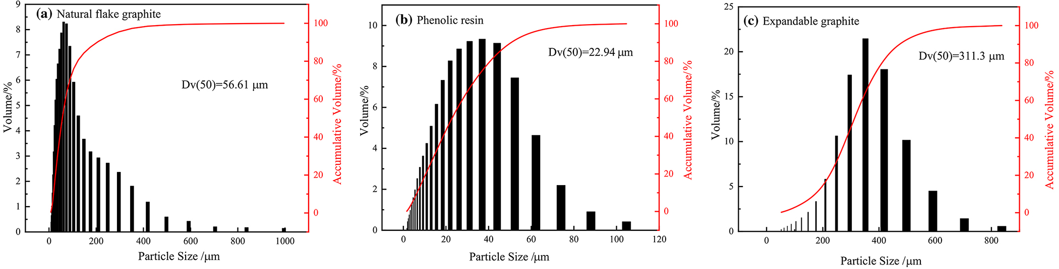
Natural flake graphite powder (99.5% carbon, D50 = 56.61 µm, supplied by Yichang Xincheng Graphite Co., Ltd.), thermosetting phenolic resin powder (SG-3130, D50 = 22.94 µm, supplied by Shanghai Aotong Industrial Co., Ltd.), and expandable graphite powder (99.5% carbon, D50 = 311.3 µm, supplied by Qingdao Xinghua Graphite Products Co., Ltd) were used.
Figure 1 shows the particle size distribution of natural flake graphite, thermosetting phenolic resin, and expandable graphite.
Experimental procedures
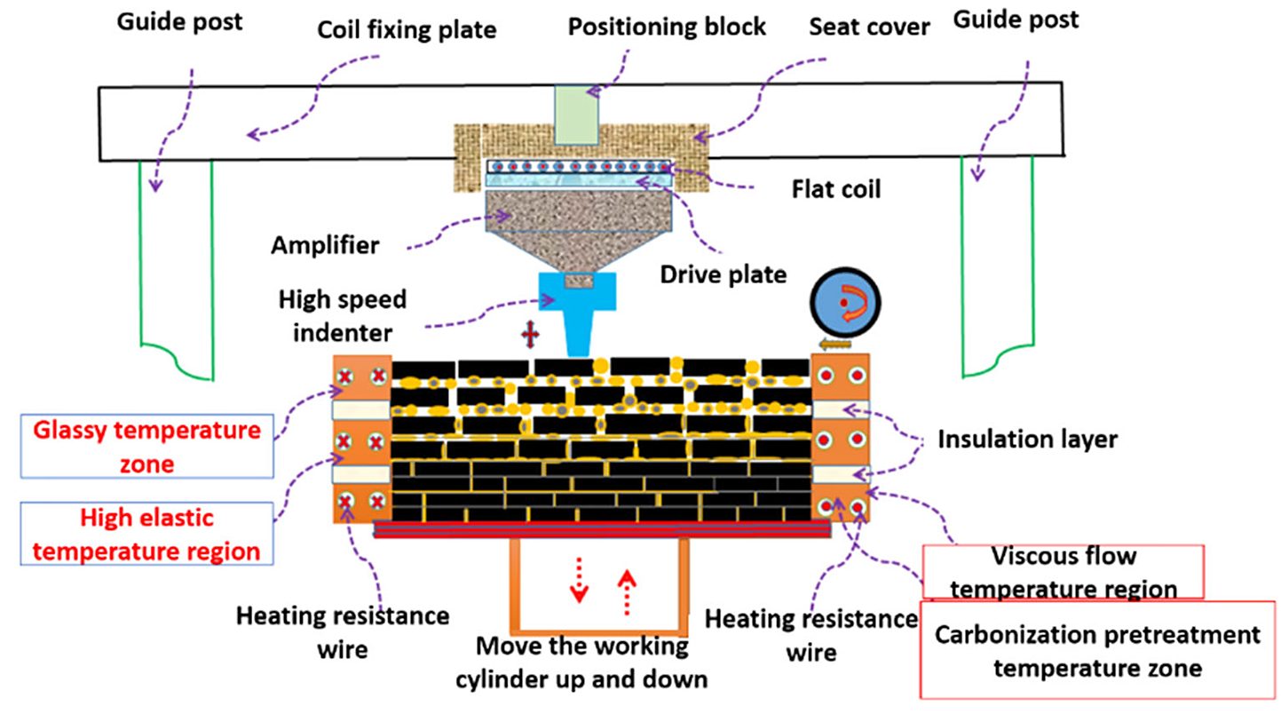
Natural flake graphite, thermosetting phenolic resin, and expandable graphite were weighed in batches in a dry ball mill of type GQM (Xianyang Jinhong General Machinery Co., Ltd.) in established mass ratios and mixed well and then transferred to a micro-thermal pressing additive manufacturing forming system. The process can be summarized as follows: The graphite/phenolic resin/expandable graphite powder mix was laid flat, and, under the shear of the laying rollers, the natural flake graphite powder was deflected and oriented. The heated powder was rapidly struck in the selected area by using an electromagnetic indenter. The density of the billet was controlled by controlling the distance by which the indenter was lowered, and the compression of the powder layer was controlled by adjusting the speed of the indenter strike. The layers were stacked to obtain graphite-molded parts with a controlled density (Figure 2).
The prepared preform was placed in a vacuum sintering furnace for charring (evacuated to less than 100 Pa; ramped up to 300°C at 60°C/h and then ramped up to 800°C at 30°C/h for 1 hour, and cooled with the furnace), and the charred specimen was obtained.
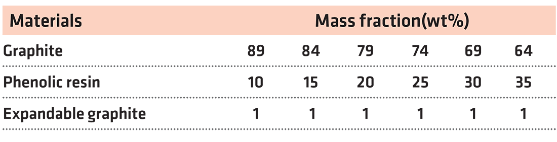
The specimen preparation process was divided into three parts: (1) Variation in the forming density of the specimen. The uncoated expandable graphite was uniformly mixed with natural flake graphite powder and thermosetting phenolic resin powder according to the mass ratios listed in Table 1, and the micro-thermoforming system was used to prepare graphite pieces with forming densities of 1.0, 1.1, 1.2, 1.3, and 1.4 g·cm-3, with five specimens for each group. (2) Variation in the amount of thermosetting phenolic resin added. The thermosetting phenolic resin powder and natural flake graphite powder were mixed evenly according to the mass ratios presented in Table 2, and specimens with a forming density of 1.2 g·cm-3 were prepared with five specimens for each group. The specific material ratios are listed in Table 2. (3) Pretreatment of the expandable graphite powder with coating. The expanded graphite was pre-treated using a boiling coating dryer (Changzhou Xinma Drying Engineering Co., Ltd.). (The coating solution consisted of 40 wt% liquid phenolic resin mixed with anhydrous ethanol at a mass ratio of 1:3, and the coating treatment was performed twice.) The expanded graphite was crushed after coating and sieved using a 200 mesh. The untreated expandable graphite, expandable graphite with one overcoating treatment, and expandable graphite with two overcoating treatments were mixed with natural flake graphite and thermosetting phenolic resin in accordance with the mass ratios listed in Table 1 to prepare specimens with a density of 1.2 g·cm-3, with five specimens prepared for each group.

Performance characterization
To distinguish the types of pores, the bulk density and porosity of the specimens were tested according to GB/T 2998-2015 and international standard ISO 5016:1997, and the open porosity of the specimens was tested with reference to GB/T24529-2009. The closed porosity of the specimens was calculated as Pε=(1 − Db/Dt × 100\% ) − Pα (Db is the bulk density of the specimens in g·cm-3, Dt is the theoretical density of graphite, considered to be 2.256 g·cm-3, and Pα is the specimen open porosity). The bulk density of the carbon-graphite heat insulation material specimen was calculated as ρ = m/υ. Moreover, the compressive strength of the specimen was tested with reference to GB/T 13,465.3–2014, and the maximum compressive load of the specimen (Ø25 mm ± 0.1 mm) × (25 mm ± 0.1 mm) was determined using a WDW-100E micro-controlled electronic universal testing machine (provided by Jinan Kehui Experimental Equipment Co.). The arithmetic mean of the obtained experimental data was determined. (In the experiment, the indenter applied the load uniformly and without impact at 15 mm/min, and the effective number of specimens for each group was 6.) The thermal conductivity of the specimens (Ø30 mm × 10 mm, six specimens in each group) was tested using a DRE-III thermal conductivity measurement instrument (provided by Xiangtan Xiang Yi Instrument Co., Ltd.). The specimens were transformed to optical sheets, and the JSM-7000F cold field emission scanning electron microscope was used to measure the thermal conductivity of the specimens. The aperture distribution and size of the specimens (10 mm × 10 mm × 10 mm) were evaluated using an AutoPore lv 9510 high-performance automatic mercury piezometer (supplied by Shanghai McMurray-Tick Instruments Co.)
Results and discussion
Effect of forming density on the properties of carbon-graphite insulation
Figure 3 shows the microscopic profile of a section of the carbon-graphite insulation material and its pore size distribution curve at different forming densities. Table 3 shows the test results of the mercury injection method. The average pore size of the carbon-graphite insulation was 1058.9 nm, 807.6 nm, and 659.7 nm at forming densities of 1.0, 1.2, and 1.4 g·cm-3, respectively. The porosity decreased from 72.6452 to 58.7736% and 54.1115% as the forming density increased. This finding indicated that increasing the forming density led to a decrease in the number and size of pores within the carbon-graphite insulation.
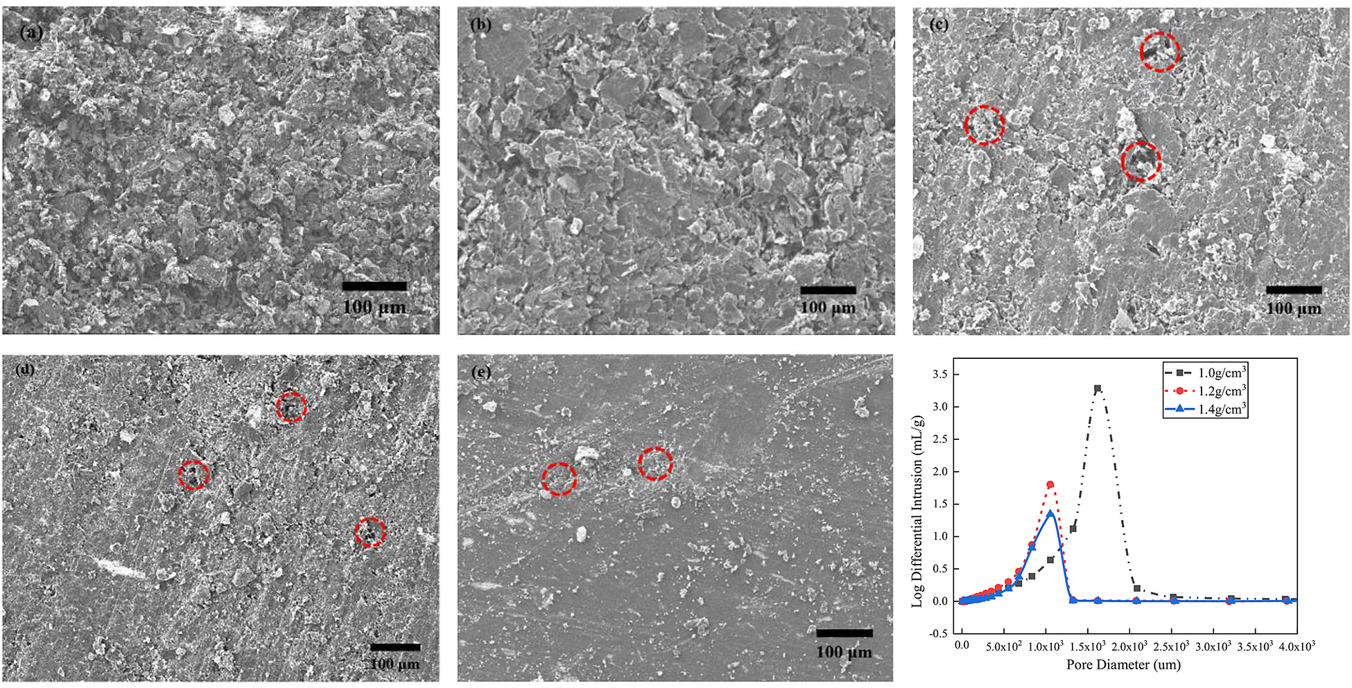
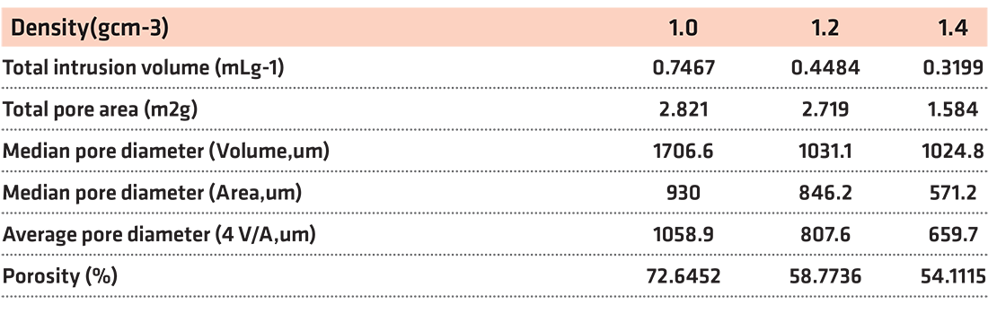
Figure 4a shows the variation in the porosity, open porosity, and closed porosity of the carbon-graphite insulation material under different forming densities. As the density increased from 1.0 to 1.4 g·cm-3, the porosity and open porosity decreased from 61.402% and 45.351% to 36.417% and 12.439%, respectively, and the closed porosity increased from 15.826 to 23.762%; moreover, the proportion of closed porosity gradually increased to 65.25%. In other words, increasing the forming density reduces the porosity of the carbon-graphite composite insulation and leads to the formation of more closed pores inside it. This phenomenon occurs because, during the micro-hot pressing process, the thermosetting phenolic resin becomes viscous and ensures the adhesion of the graphite powder and expandable graphite powder. Moreover, during the high-temperature carbonization process, the thermosetting phenolic resin undergoes a pyrolysis reaction, releasing CO2, H2, and water vapor (physicochemical process), and the H2SO4 and HNO3 in the expandable graphite decompose into SO2, CO2, and a small amount of NOx (Figure 5). When the forming density is low, owing to the low resistance, the gas generated can rapidly escape, leading to the formation of pores inside the carbon-graphite insulation. In this stage, the number of open pores is more. However, as the forming density continues to increase, gas discharge becomes more difficult. Part of the gas cannot be eliminated in time, leading to the formation of closed pores, and the number of closed pores increases. The continuous escape of gas during carbonization is the fundamental reason for the formation of pores within the carbon-graphite insulation, and the forming density directly influences the form of porosity.
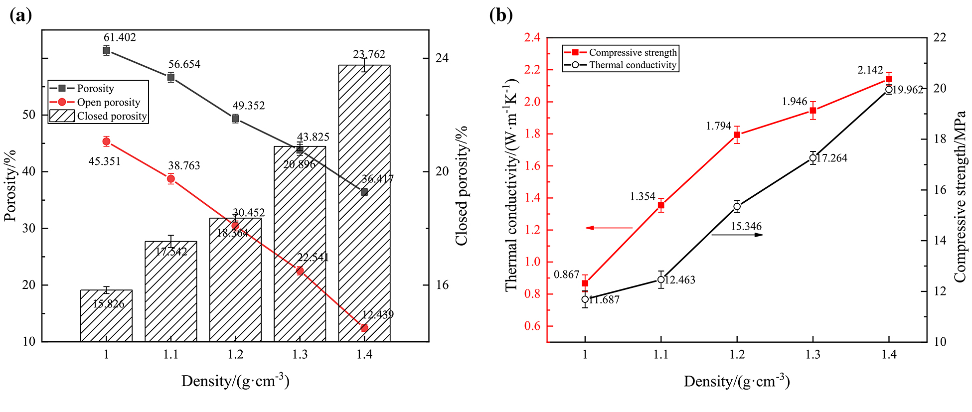
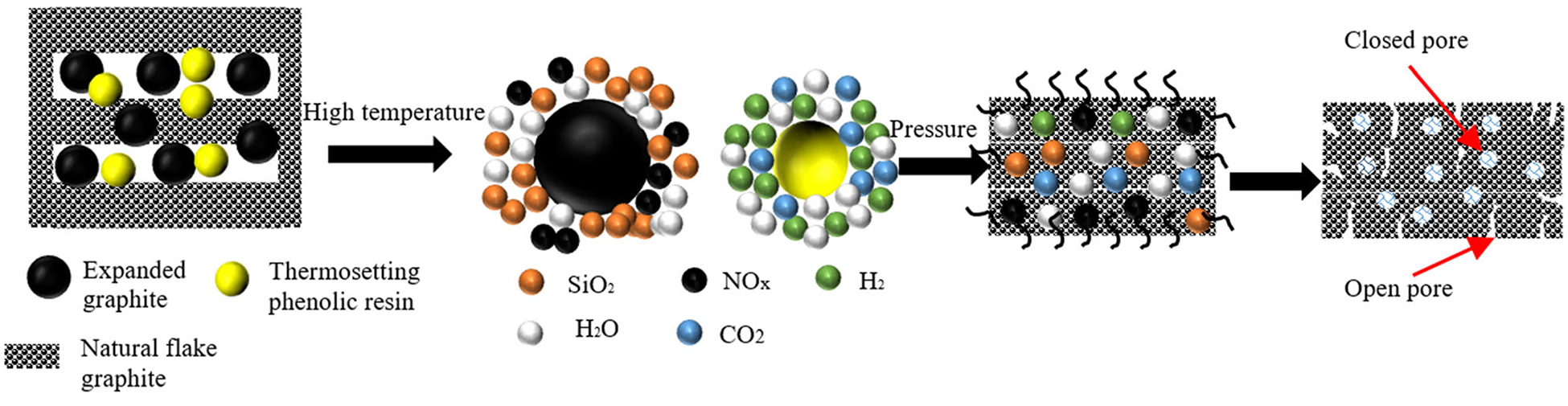
Figure 4b shows the variation in the compressive strength and thermal conductivity of the carbon-graphite insulation material at different forming densities. Both the compressive strength and thermal conductivity of the material grew with the increase in the forming density. Specifically, as the density increased from 1.0 to 1.4 g-cm-3, the compressive strength and thermal conductivity increased from 11.687 MPa and 0.867 W·m-1 K-1 to 19.962 MPa and 2.142 W·m-1 K-1, respectively, corresponding to an increase of 70.81% and 1.47, respectively. This phenomenon occurred because, as the forming density of the preform increases, the graphite flake layer undergoes plastic deformation and orientation, leading to a stronger bond between graphite flakes, and the closed porosity increases [12]. At the same time, the vertical transmission of heat flow between carbon-graphite insulation materials changes from heat radiation to heat radiation and heat conduction, resulting in the increase of compressive strength and thermal conductivity of preforms [13].
Effect of thermosetting phenolic resin addition on the properties
of carbon-graphite materials
Figure 6 shows the effect of the addition of thermosetting phenolic resin on the microscopic morphology of the carbon-graphite insulation material. In general, in the forming process of the micro-hot press additive manufacturing procedure, under the combined effect of the temperature field, shear force of the powder laying roller, and electromagnetic force, the natural scaled graphite powder is deflected and aligned along the direction perpendicular to the pressure, and the thermosetting phenolic resin is “distributed” as the binder. When the added content is low, the resin is mostly in the form of “lonely spots.” At this time, there are a large number of pores inside the specimen, and the compressive strength and thermal conductivity are low, as shown in Figure 6a and 6b. When the added content is high, the molten thermosetting phenolic resin flows between the graphite flakes, filling the pores. Thus, the number of pores in the specimen gradually reduces, the microstructure becomes denser, and the graphite flakes are more flatly oriented (Figure 6c, 6d, and 6e). Consequently, the compressive strength, and thermal conductivity of the specimen increase with the addition of phenolic resin.
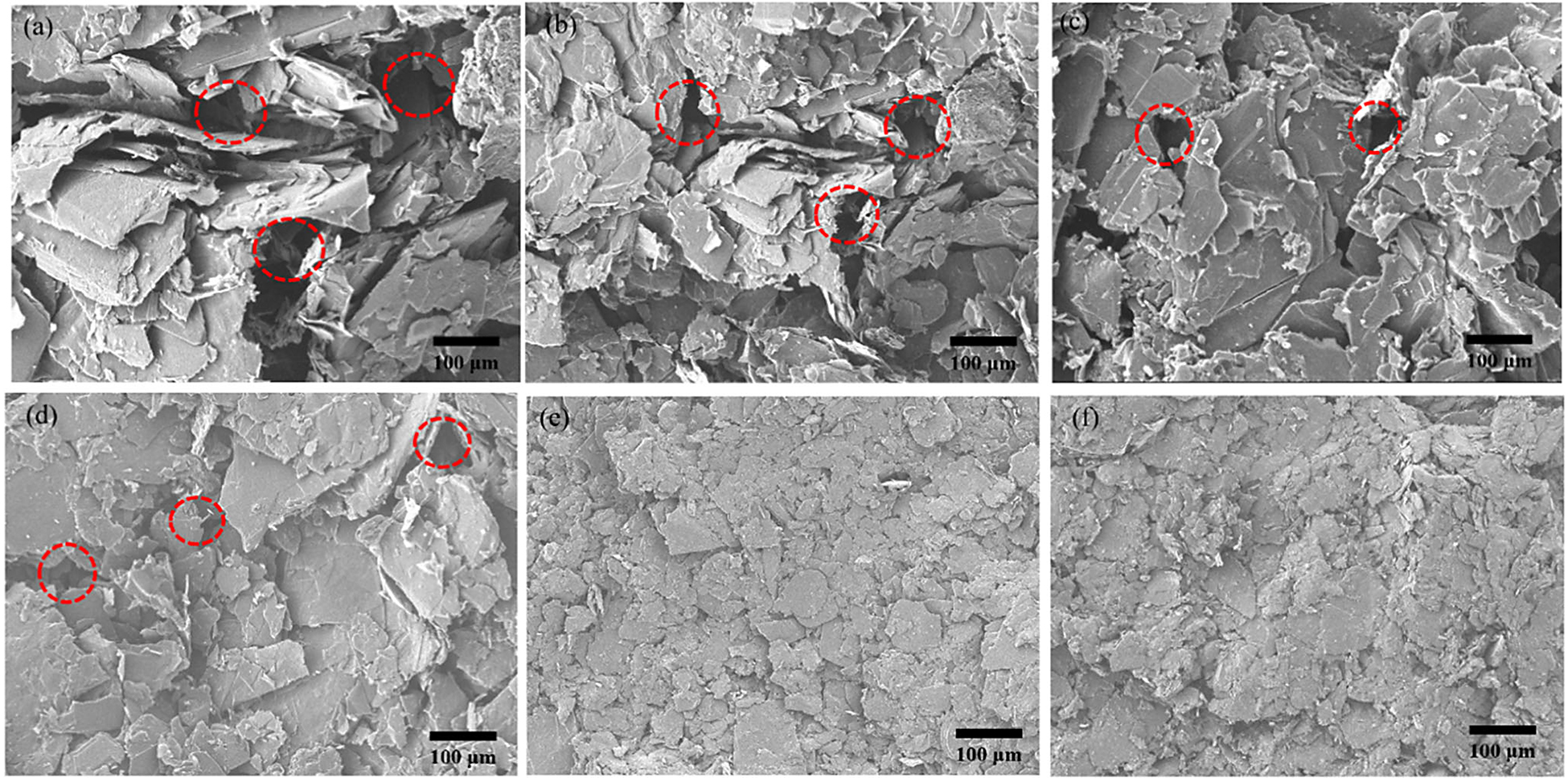
Figure 7a shows the effect of the addition of different amounts of thermosetting phenolic resin powder on the porosity, open porosity, and closed porosity of the specimens. As the amount of added thermosetting phenolic resin powder increased from 10 to 35%, the porosity of the specimens decreased from 53.167 to 43.354%, and open porosity decreased from 46.376 to 25.143%, indicating that the closed porosity gradually increased. When the added content of phenolic resin powder was 35%, the closed porosity was the highest (19.421%), with a proportion of44.80%. This phenomenon occurs because as the amount of thermosetting phenolic resin added increases, a larger amount of thermosetting phenolic resin fills the gaps between the graphite sheets under the action of the micro-hot pressing forming temperature and pressure. During charring, a larger amount of gas escapes, forming more holes; however, the larger amount of resin char remaining (phenolic resin residual carbon rate is as high as 70–80%) fills the spaces between the graphite sheets, reducing the number of holes, and resin carbon shrinks by 2% volume at high temperatures. Moreover, the addition of more thermosetting phenolic resin makes it more difficult for gases to escape, leading to the formation of more closed pores inside the specimen. The combined result of these factors leads to a decrease in the total and open porosities of the carbon-graphite insulation [14].
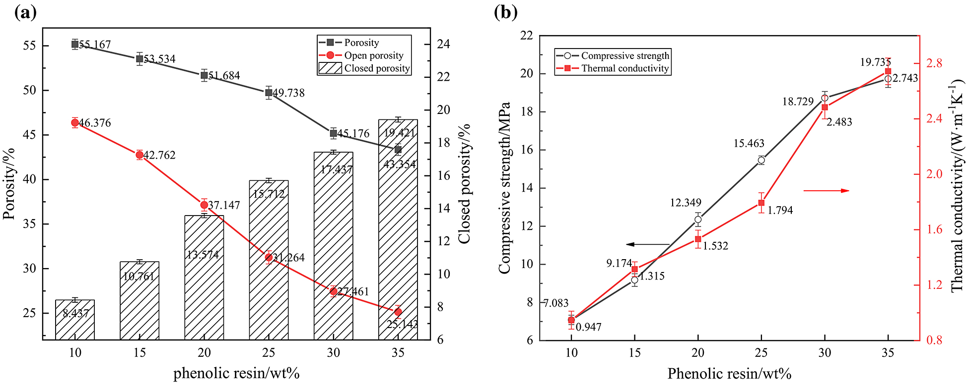
Figure 7b shows the effects of addition of different amounts of thermosetting phenolic resin powder on the compressive strength and thermal conductivity of the charred specimens. The compressive strength and thermal conductivity increased with the addition of thermosetting phenolic resin powder. Specifically, when the amount of added thermosetting phenolic resin powder increased from 10 to 35wt%, the compressive strength increased from 7.083 MPa to 19.735 MPa and thermal conductivity increased from 0.974 W·m-1 K-1 to 2.743 W·m-1 K-1, corresponding to an increase of 178.62% and 189.65%, respectively.
In summary, although the increase in the forming density or amount of added thermosetting phenolic resin increases both the compressive strength and thermal conductivity, increasing the forming density has a more notable effect on the thermal conductivity of the carbon-graphite material and increasing the amount of the added thermosetting phenolic resin has a more notable effect on the compressive strength. Notably, in both cases, the closed porosity ratio of the carbon-graphite insulation material increases, owing to which the compressive strength and thermal conductivity simultaneously increase. In general, it is difficult to simultaneously achieve low thermal conductivity and high compressive strength.
Influence of expandable graphite cladding condition
on the performance of carbon-graphite insulation
The internal microscopic morphology of the carbon-graphite insulation material showed the uncoated preform was loose and porous, and most of the holes were irregularly shaped open pores (Figure 8a). After the primary coating of expandable graphite, the number of internal pores of the preform significantly reduced, and open and closed pores existed simultaneously. Moreover, the internal “gullies” of the preform reduced, and the morphology became smoother and flatter (Figure 8b). When expandable graphite was clad two times, the number of holes inside the preform was significantly reduced, the number of pores decreased, and the surface became smoother and flatter. In general, the particle size of expandable graphite considerably influences the degree of expansion and distribution range of pores, and the expandable graphite without cladding and crushing treatment exhibits a large particle size, high degree of expansion, and small expansion range at a high temperature (800°C). Thrust causes the graphite carbon layer to expand outward, resulting in a larger number of non-closable holes in the precast body [15]. In contrast, the expandable graphite subjected to cladding and crushing has a smaller particle size and wider distribution, and the impact force of the expansion process is dispersed. As the phenolic resin adheres to the material surface, its adhesion to the graphite sheet increases; it becomes difficult to expel the gas during the expansion process, and more closed gas holes are produced. Yang et al. used Madagascar purified graphite as the raw material to prepare high-rate expandable graphite and conducted expansion experiments on expandable graphite with different grain sizes to measure the volume after expansion at 850°C. The results showed that, for the same mass of graphite, a larger graphite sheet corresponded to a larger expansion volume of the expandable graphite, and the expansion volume of +0.300 mm grain size expandable graphite was four times larger than that of the expandable graphite with a grain size of minus-0.150 mm, with a value of up to 480 m L·g-1 [16]. Zhang et al. demonstrated that expanded graphite consists of a number of “microcells” connected to form a macroscopic graphite worm, with irregular elliptical pores in the microcells. The microcellular structure has many tiny pores at the microscopic level, forming a unique and rich pore structure of expanded graphite [17]. This aspect is in accordance with the microstructure shown in Figure 8.
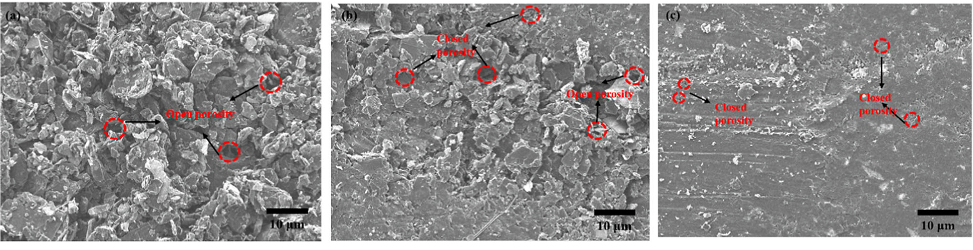
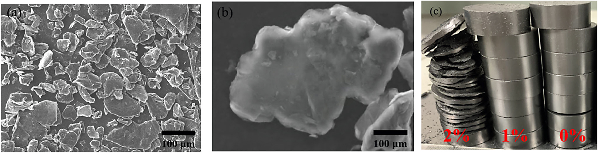
Figure 9a shows the effect of the number of expandable graphite cladding treatments on the porosity, open porosity, and closed porosity of the carbon-graphite insulation. The porosity and closed porosity increased with the number of wraps, whereas the open porosity tended to decrease. The preform porosity, open porosity, and closed porosity were 56.754%, 28.741%, and 27.762%, respectively, when cladding was performed twice. The proportion of the closed porosity was 48.92%, slightly lower than that of the open porosity. After coating treatment, the surface of expandable graphite shows a spheroidizing trend (see Figure 7), which made it easier for the pores between the graphite flakes to be filled. Moreover, because the surface was covered with phenolic resin, the connection state between the expandable graphite and surrounding graphite flakes was modified, which enhanced the bonding ability and created more favorable conditions for the high-temperature expansion to produce closed pores. In addition, the volume shrinkage of the phenolic resin residue at high temperatures (approximately 2%) facilitated the formation of closed pores. The compressive strength of the carbon graphite insulation increased with the number of wraps, whereas the thermal conductivity gradually decreased, with values of 16.432 MPa and 0.743 W·m-1 K-1, respectively, after two wraps (Figure 9b). It is worth pointing out that the amount of expandable graphite added is not the better. It was found that, when expandable graphite was added at more than 2%, the carbon-graphite insulation cracked after charring, as shown in Figure 10.
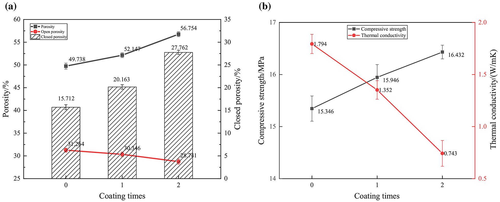
After two cladding treatments of the expandable graphite, the proportion of closed porosity of the carbon-graphite insulation considerably increased. The compressive strength slightly increased, and the thermal conductivity significantly reduced, thereby achieving the synergy of the technical objectives of a low thermal conductivity and high compressive strength.
Thermal and mechanical modeling of carbon-graphite insulation
Various models have been developed to predict the effective thermal conductivity of porous materials, with representative models being the Maxwell-Eucken and EMT equations. The Maxwell–Eucken model [18] assumes the dispersed phase involves spherical particles irregularly dispersed in a continuous phase without contact with one another, and the equations can be expressed as Equations 1 and 2. The EMT equation [19] assumes that, in a composite system, either the components or the filler are surrounded by a homogeneous effective medium. The thermal conductivity of the effective medium is the thermal conductivity of the composite system, and the equation can be expressed as Equation 3.
Maxwell–Eucken 1:


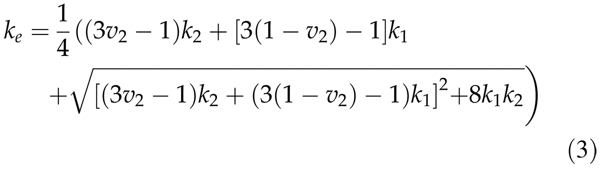
where ke is the effective thermal conductivity of the porous insulation, k1 is the graphite phase thermal conductivity(5.6 W·m-1 K-1), k2 is the air thermal conductivity (0.026 W·m-1 K-1), υ1 is the graphite phase volume fraction, and υ2 is the volume fraction of air.
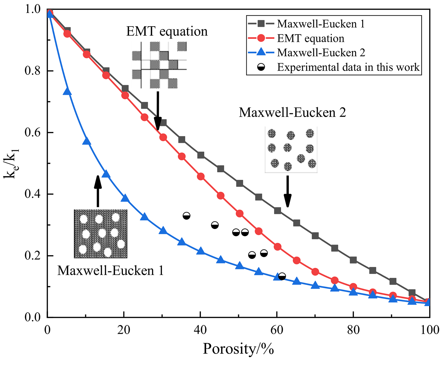
The porous carbon-graphite insulation is considered a two-phase system consisting of a carbon-graphite skeleton and air. Figure 11 shows a comparison of the three thermal conductivity models, and the experimental data were obtained in this study. The experimental data lie in between those of the EMT equation and Maxwell-Eucken 2, and the relative thermal conductivity is lower than the value predicted using the EMT equation. This phenomenon occurs because the effective thermal conductivity depends on the porosity and microstructure of the two phases. In the carbon-graphite insulation, the dense graphite/phenolic resin skeleton is the continuous phase, and air is the dispersed phase. The phenolic resin has a lower thermal conductivity than natural scale graphite and produces a large number of pores during pyrolysis, which reduces the average free travel of phonons during heat transfer. Moreover, the expandable graphite produces a large number of small closed pores, which reduces the point contact within the carbon-graphite insulation and solid phase heat transfer within it.
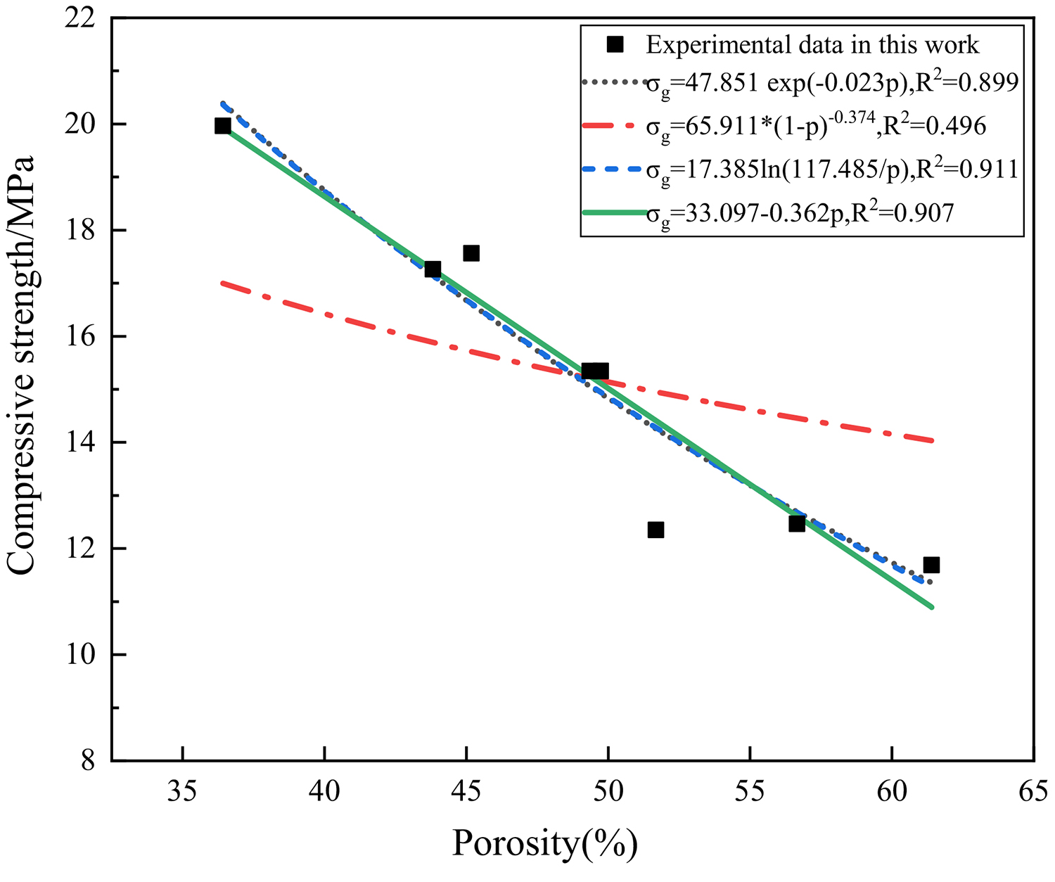
To clarify the relationship between the compressive strength and porosity, the experimental data were validated using the power function and logarithmic, exponential, and linear models proposed by Balshin, Schiller, Ryshkewitch, and Hasselman [20]. The models are defined in the following equations, and the fitting results of these models to the experimental data are shown in Figure 12.
Ryshkewitch equation:
![]() Balshin’s power function model:
Balshin’s power function model:
![]() Schiller’s logarithmic function model:
Schiller’s logarithmic function model:
 Hasselman’s linear relationship between the strength and porosity of refractory materials:
![]() where σg is the compressive strength of the carbon-graphite insulation (MPa), σ0 is its theoretical strength in the non-porous state, p is the porosity, and n is an empirical constant.
where σg is the compressive strength of the carbon-graphite insulation (MPa), σ0 is its theoretical strength in the non-porous state, p is the porosity, and n is an empirical constant.
Figure 12 shows that the correlation coefficients of the experimental data with three empirical models are high (0.899, 0.911, and 0.907), although the fitting with the power function model proposed by Balshin (R2 = 0.496) is low. This finding shows the experimental data obtained in this study fit well with all equations except for the power function model. Notably, the porosity and compressive strength are negatively correlated, and the compressive strength progressively decreases with increasing porosity. The data presented in the previous section are consistent with this trend. When the expandable graphite is not pre-treated with cladding, the closed porosity generated within the carbon-graphite material by the cladding treatment is considerably greater (approximately 10%) than that produced when the carbon-graphite material is not clad, accompanied by a small increase in the compressive strength (approximately 7.08%). Future work must be aimed at modeling the effect of closed pores on the mechanical properties of porous insulation materials.
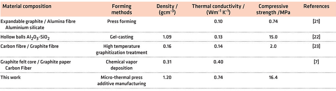
A comparison of the low thermal conductivity and high-strength carbon-graphite insulation prepared in this study and other lightweight insulation materials is shown in Table 4. The carbon-graphite insulation material exhibits a higher compressive strength than other lightweight insulation materials, although its thermal conductivity is slightly higher. Future work can be aimed at reducing the forming density of graphite parts, increasing the porosity of graphite parts, and further reducing the thermal conductivity of the carbon-graphite insulation while maintaining its compressive strength.
Conclusion
Carbon-graphite thermal insulation materials with synergistic functional objectives such as a low weight, thermal insulation, high compressive strength, and high-temperature resistance were prepared by micro-thermal pressing additive manufacturing technology. The creation of closed pores in the carbon-graphite insulation material can modify the compressive strength and thermal conductivity of the material, specifically, a reduction in the thermal conductivity and enhancement in the mechanical properties. With the increase in the forming density and addition of thermosetting phenolic resin, the porosity and open porosity of the carbon-graphite insulation materials decreased, whereas the proportion of the closed porosity, compressive strength, and thermal conductivity increased. Increasing the forming density of the carbon-graphite insulation had a more notable effect on the thermal conductivity, whereas increasing the amount of added thermosetting phenolic resin had a more significant effect on the compressive strength.
The creation of closed pores inside the carbon-graphite insulation material can adjust its compressive strength and thermal conductivity in both directions, reducing its thermal conductivity and improving its mechanical properties. By fitting the experimental data, the thermal conductivity model and mechanical model suitable for carbon-graphite thermal insulation materials were obtained.
Acknowledgements
This study was supported by the National Natural Science Foundation of China (51575313) and the State Key Laboratory of Material Forming and Mould Technology, Huazhong University of Science and Technology Open Project Research Fund (P2020-003).
Declarations
Conflict of interest: The authors declared that there is no conflict of interest.
Additional information
Handling editor: Jaime Grunlan.
Publisher’s Note
Springer Nature remains neutral with regard to jurisdictional claims in published maps and institutional affiliations.
References
- Pulci G, Tirillò J, Marra F, Fossati F, Bartuli C, Valente T (2010) Carbon–phenolic ablative materials for re-entry space vehicles: manufacturing and properties. Compos Part A-Appl S 41:1483–1490
- Yang YZ, Yang JL, Fang DN (2008) Research progress on thermal protection materials and structures of hypersonic vehicles. Appl Math Mech 29:51–60
- Li TQ, Xu ZH, Hu ZJ, Yang XG (2019) Application of a high thermal conductivity C/C composite in a heat-redistribution thermal protection system. Carbon 48:924–925
- Guo (2019) Preparation of new low density C/C thermal insulation material. PhD Dissertation ,Central South University
- Lin Y, Liu B, Fei CW (2021) Study on impact resistance of C/SiC ceramic matrix composites for thermal protection of the aerospace vehicle. Math Probl Eng. https://doi.org/10.1155/2021/6255014
- Yang XG, Sun YT, Shi DQ, Liu JL (2011) Experimental investigation on mechanical properties of a fiber-reinforced silica aerogel composite. Mat Sci Eng A-Struct 528:4830–4836
- Wang Y, Chen ZF, Yu SJ, Saeed MU, Luo RY (2016) Preparation and characterization of new-type high-temperature vacuum insulation composites with graphite felt core material. Mater Design 99:369–377
- Wu XW, Luo RY (2011) Mechanical properties investigation of carbon/carbon composites fabricated by a fast densification process. Mater Design 32:2361–2364
- Han MK, Yin XW, Chen LF, Rena S, Li ZK (2016) Effect of core-shell microspheres as pore-forming agent on the properties of porous alumina ceramics. Mater Design 113:384–390
- Chen S, CaiWH WuJM, Ma YX, Li CH, Shi YS, Yan CZ, Wang YJ et al (2020) Porous mullite ceramics with a fully closed-cell structure fabricated by direct coagulation casting using fly ash hollow spheres/kaolin suspension. Ceram Int 46:17508–17513
- Wu HH, Chen K, Li YF, Ren CQ, Sun Y, Huang CH (2020) Fabrication of natural flake graphite/ceramic composite parts with low thermal conductivity and high strength by selective laser sintering. Appl Sci-Basel. https://doi.org/10.3390/app10041314
- Guo XB (2018) Preparation and properties of mesophase pitch based carbon / Carbon Composites .PhD Dissertation, Aerospace Power Technology Research Institute
- Li SS (2011) Preparation and oxidation resistance of carbon graphite materials. PhD Dissertation, Hunan University
- Zhong J, Guo HM, Xie Z, Zhao SM (2018) Firing mechanism of oxide-carbon refractories with phenolic resin binder. Ceram Int 44:5594–5600
- Qi MM (2017) Study on microstructure regulation and properties of carbon composites.PhD Dissertation, TianJin University
- Yang L, Zhang LY, Qiu YS, Wang J (2019) Preparation and study of expansible graphite from madagascar. Bull Chinese Ceramic Soc 38:3320–3325
- Zhang HG( 2007) Study on sulfur free and ash free expandable graphite.Master Dissertation, QingDao University
- Gong LL, Wang YH, Cheng XD, Zhang RF, Zhang HP (2013) Thermal conductivity of highly porous mullite materials. Int J Heat Mass Tran 67:253–259
- Hashin Z, Shtrikman S (1962) A variational approach to the theory of the effective magnetic permeability of multiphase materials. J Appl Phys 33:3125–3131
- Odler I (1991) Strength of cement (final report). Mater Struct 24:143–157
- Fang K (2016) Study on preparation and performance of an alumina-fiber-based expandable insulation material. Master Dissertation, China Building Materials Research Institute
- Huang CS (2011) Preparation and property study of porous lightweight mullite ceramics. TianJin University, Master Dissertatio
- Friedrich W, Qian CS, Wang YH (1983) High temperature insulation material made of carbon fiber and graphite fiber. Carbon Tech 03:11–13
©The Author(s) 2022. This is an open access article (https://link.springer.com/article/10.1007/s10853-021-06862-6) distributed under the terms and conditions of the Creative Commons Attribution (CC BY) license (https://creativecommons.org/licenses/by/4.0/).
The article has been edited to conform to the style of Thermal Processing magazine.


 general practice for CQI-9 and AMS2750E")


