


Induction hardening is a unique method used to harden steels. The process uses a power supply, RF generator, induction coil, and quenching mechanism (spray or immersion) to yield a high surface hardness and advantageous residual surface stresses. The process can be highly automated and results in high production rates with uniform results. Heating is very fast, with selective heating of the desired part. An induction hardening line can be integrated readily into cellular manufacturing.
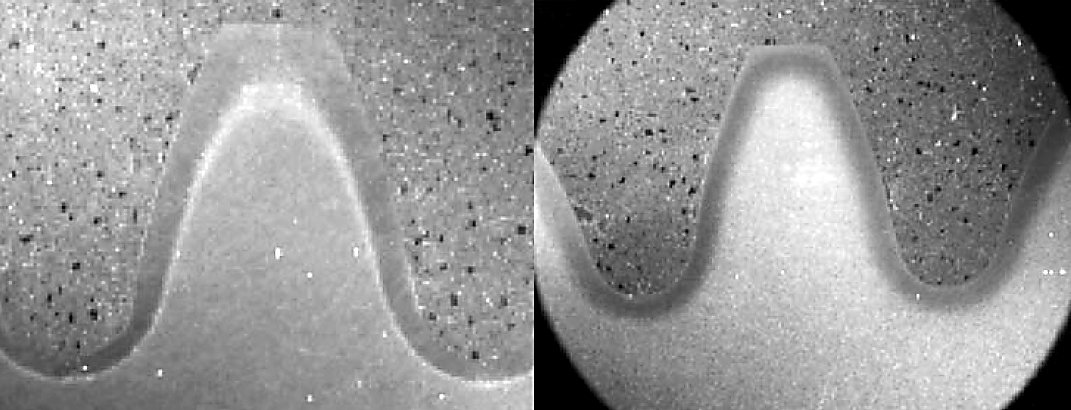
It is commonly used to heat treat gear teeth, shafting, and other parts that require a high surface hardness for wear or strength. The native hardenability of the steel is used to obtain the surface hardness. For this reason, medium- to high-carbon steels are used. Typically, carbon contents between 0.4 to 0.6 percent carbon are used in induction hardening. Alloy content can vary, depending on the desired depth of hardening and the required core hardness. The resulting hardened part offers excellent control of distortion compared with conventional carburizing, with practically identical mechanical properties [1]. A comparison of an induction-hardened gear tooth and a carburized gear tooth is shown in Figure 1.
Problems During Induction Hardening
There are many problems that can occur in induction hardening that can have nothing to do with the power supply, RF generator, or coil. These are process-related issues that can be traced back to improper or inadequate process control. These problems can manifest themselves as improper part hardness or cracking; improper pattern; quenching issues such as foaming or excessive drag-out; corrosion issues; or biological issues such as bacteria and fungus, or odors. In this article and next month’s, we will discuss several of these issues and ways to troubleshoot corrective actions. This month, I will cover hardness or cracking, excessive polymer consumption or drag-out, and foaming.
Low Hardness and Mechanical Properties or Distortion and Cracking
Low hardness and mechanical properties are usually associated with poor quenching. Occasionally, it is found that the part has not been properly heated to the austenitizing temperature, or that inadequate dwell time has been used. However, this is not common. Poor properties can often be traced to either improper quenchant concentration, excessive quenchant temperature, or poor or non-uniform agitation. Contamination of the quenchant can also cause problems with achieving proper quenching [2].
The quenchant used (predominantly polymer quenchants) need to be controlled to achieve a stable concentration. This is usually accomplished using a simple optical or digital refractometer. The refractometer should be properly calibrated according to the manufacturing recommendations. Concentration is usually determined by taking a reading in °Brix on the optical or digital refractometer. This reading is then multiplied by the factor supplied by the manufacturer to determine the concentration of the polymer. This concentration should also be verified by the manufacturer at routine intervals, or in-house using kinematic viscosity. The multiplying factor can change due to differences in water — reverse osmosis vs. hardwater — or due to contamination. Contamination and harder water tend to make the factor drift downward due to the increased solids present.
Concentration should be determined at least once per shift. The actual number depends on the parts processed per hour, and the amount of drag-out experienced. Even if the drag-out is low, the concentration can creep upwards due to the evaporation of water. In most cases, water is added more often to quench tanks than is polymer due to evaporation. For most applications, the concentration should be controlled within ± 2 percent (or 1°Brix depending on the quenchant multiplying factor). Tighter control is better, but measuring the difference becomes problematic, depending on the refractometer chosen.
The optical refractometer should have a narrow range. This increases the reliability and reproducibility of the measurement. For most optical refractometers, it is difficult to measure tighter than 0.5 – 1.0° Brix. For digital refractometers, it is much easier to achieve repeatable measurements within ± 0.25° Brix.
Polymer quenchants are very sensitive to the bulk temperature. Polymer quenchants tend to slow down the heat extraction rate as the bulk temperature is increased. Only 10°C can have a marked change in the cooling rate. To achieve a consistent process control, the temperature of the quench bath should be controlled within ± 3°C.
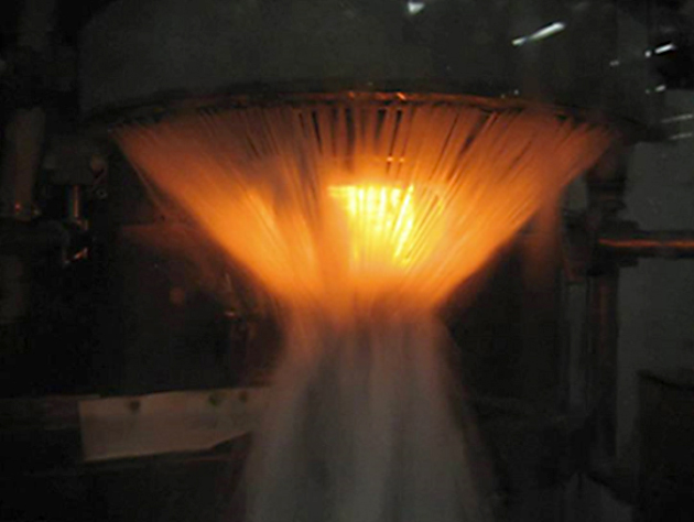
Agitation is very important. The quench ring or spray head should supply a uniform flow of quenchant to the part. Blocked holes or improper pressures can result in soft spots or even cracking (Figure 2). Filtration should be used prior to the quench ring to prevent clogging of the ports on the spray ring.
In summary, low hardness and soft spots can usually be overcome by decreasing concentration; increasing agitation and the uniformity of agitation; and decreasing the bulk quenchant temperature. Preventing contamination is also important.
Distortion and cracking of an induction-hardened part is usually related to non-uniform quenching. It can also be from a low concentration of quenchant. Overheating a part is unfortunately common from misaligned coils. Proper centering of the part within the coil is important for uniform depth of hardening and preventing cracking.
The fixes for excessive distortion or cracking are generally the opposite for low hardness. Increasing concentration or changing to a slower polymer can slow down the quench, reducing the chance for distortion. Increasing the bulk temperature of the quenchant will also slow down the quenchant. Increasing the dwell time (or distance) between the time the heat is turned “off” and the time the quench is turned “on” will reduce the thermal gradients in the part, reducing the chances of distortion or part cracking. Reducing the flow or pressure of the quenchant will also slow down the quench.
Excessive Polymer Consumption or Drag-Out
Excessive polymer drag-out or consumption can be related either to the quenchant used or the geometry of the part. Polymers work by creating a polymer film on the part instead of a stable vapor phase. During the vapor phase, heat transfer is slow, and usually by radiation. Non-uniform rupture of the vapor phase can result in distortion. A polymer creates a film of polymer around the part, and heat transfer is by conduction. Heat transfer is more uniform and rapid. At a certain point, depending on surface temperature and other factors, the film will rupture uniformly. This creates uniform heat transfer, with resulting uniform residual stresses. Distortion is reduced.
If the part exit temperature from the quenchant is too high, or inadequate time is allowed for the polymer to dissolve back into solution, then excessive drag-out can result. Usually a cure for this is longer dwell times in the quenchant, allowing the part to cool below the cloud point of the quenchant, or allowing the polymer to dissolve back into the water.
Alternatively, different types of polymers can be used to reduce drag-out. Use of lower solids quenchants can reduce residual films on parts and reduce polymer consumption. Excessive polymer drag-out can also be reduced or recovered by recycling or reclaiming polymer from exiting parts. However, care must be taken to prevent removing additives that may prevent other problems like rusting and biological growth.
Foaming
Foaming is usually a mechanical issue. Leaky seals on pumps, or excessive pressures can contribute to foaming. Excessing spray pressures can also create excessive foaming. Inadequate fluid levels resulting in a vortex on the suction side can entrain air, which comes out of solution at the pressure drop at the spray, creating foam. Defoamers can be added, but usually it is better to increase fluid levels or repair pump seals so that the problem is fixed, instead of just maintained.
In Part 2 next month, I will discuss biological and odor problems, and corrosion issues.
Should you have any questions regarding this article, or have suggestions for new articles, please contact the editor or the author.
References
- K. T. Jones, M. R. Newsome and M. D. Carter, “Gas Carburizing vs. Contour Induction Hardening in Bevel Gears,” Gear Solutions, pp. 38-44, 51-54, January 2010.
- D. S. MacKenzie, L. Gunsalus and I. Lazerev, “Effect of Contamination on the Cooling Rate of Quench Oils,” in IFHTSE Conference September 11-14, 2001, Dubrovnik, Croatia, 2001.


 general practice for CQI-9 and AMS2750E")


