Gears play an essential role in the performance of many products that we rely on in our everyday lives. When we think about gears, we generally separate them into two categories: motion-carrying and power transmission. Motion-carrying gears are generally nonferrous or plastics, while load-bearing power transmission gears are usually manufactured from ferrous alloys. The focus here is on heat treating gears intended for heavy duty service.
To understand why heat treating is important, consider the model of material science (Figure 1), represented as a series of interlocking rings underscoring the interdependence of each element in the model. We see that the end use of performance capability of the product is defined by its mechanical, physical, and metallurgical properties, which are determined by the part microstructure, produced by a specific heat treatment process.
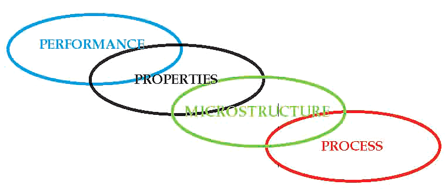
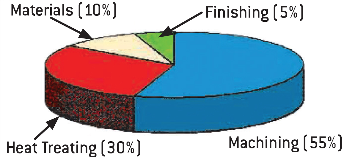
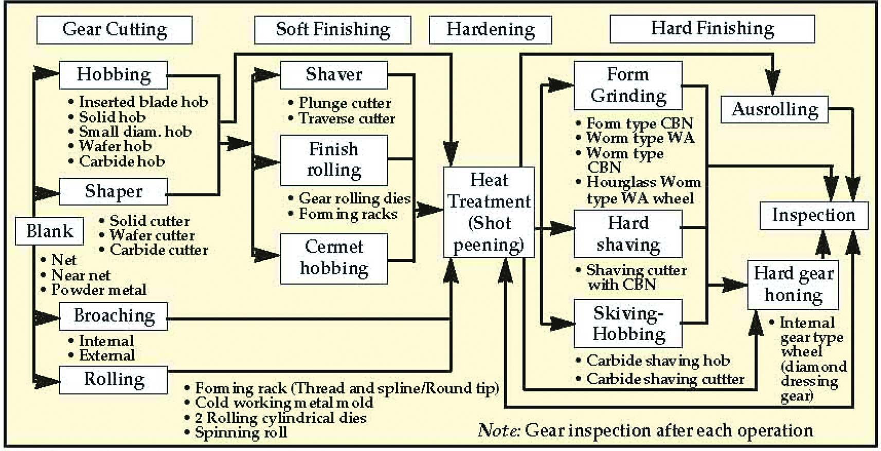
It is clear from this model that the manufacture of precision gearing depends, to a great extent, on heat treating as a core competency. Its contribution is vitally important for cost control, durability, and reliability. Heat treating represents a significant portion — about 30% — of a typical gear manufacturing cost (Figure 2). If not properly understood and controlled, it can have a significant impact on all aspects of the gear manufacturing process (Figure 3).
Process Selection
Pre-hardening Processes
Several heat treatments are normally performed during the gear manufacturing process to prepare the part for the intended manufacturing steps. These are essential to the manufacture of a quality gear.
Annealing
Annealing consists of heating to and holding at a suitable temperature, followed by cooling at an appropriate rate, primarily intended to soften the part and improve its machinability. Supercritical or full annealing involves heating a part above the upper critical temperature (AC3) — that is the temperature at which austenite begins to transform to ferrite during cooling, and then slowly cooling in the furnace to around 600ºF. Intercritical annealing involves heating the part to a temperature above the final transformation temperature (AC1), the temperature at which austenite begins to form during heating. Subcritical annealing heats the part to just below the AC1 point, followed by a slow cool in the furnace. The rate of softening increases rapidly as the annealing temperature approaches the AC1 part.
Normalizing
Normalizing involves heating the part above the upper critical temperature and then air cooling outside the furnace to relieve residual stresses in a gear blank, and for dimensional stability. Normalizing is often considered from both a thermal and microstructural standpoint. In the thermal sense, normalizing is austenitizing followed by cooling in still- or slightly-agitated air or nitrogen. In a microstructural sense, normalizing produces a more homogenous structure. A normalized part is very machinable but harder than an annealed part. Normalizing also plays a significant role in the control of dimensional variation during carburizing.
Stress Relieving
Stress Relieving involves heating to a temperature below the lower transformation temperature, as in tempering, holding long enough to reduce residual stress and cooling slowly enough, usually in air, to minimize the development of new residual stresses. Stress relief heat treating is used to relieve internal stresses locked in the gear as a consequence of a manufacturing step.
Hardening Processes
Various heat treatment processes are designed to increase gear hardness. These usually involve heating and cooling and are typically classified as through hardening, case hardening (carburizing, carbonitriding, nitriding, nitrocarburizing) and hardening by applied energy (flame, laser, induction).
Through or Direct Hardening
Through or direct hardening refers to heat treatment methods, which do not produce a case. Examples of commonly through hardened gear steels are AISI 1045, 4130, 4140, 4145, 4340, and 8640. It is important to note that hardness uniformity should not be assumed throughout the gear tooth. Since the outside of a gear is cooled faster than the inside, there will be a hardness gradient developed. The final hardness is dependent on the amount of carbon in the steel; the depth of hardness depends on the hardenability of the steel as well as the quench severity.
Through hardening can be performed either before or after the gear teeth are cut. When gear teeth are cut after the part has been hardened, surface hardness and machinability become important factors, especially in light of the fact that machining will remove some or most of the higher hardness material into the austenitic range, typically 815 to 875°C (1500 to 1600°F), followed by quenching and tempering.
Case Hardening
Case hardening produces a hard, wear resistant case or surface layer on top of a ductile, shock resistant interior, or core. The idea behind case hardening is to keep the core of the gear tooth at a level around 30 to 40 HRC to avoid tooth breakage while hardening the outer surface to increase pitting resistance. The higher the surface hardness value, the greater the pitting resistance. Bending strength increases for surface hardness up to about 50 HRC, after which the increase in bending strength is offset by an increase in notch sensitivity.
Carburizing
Carburizing is the most common of the case hardening methods. A properly carburized gear will be able to handle between 30-50% more load than a through hardened gear. Carburizing steels are typically alloy steels with approximately 0.10% to 0.20% carbon. Examples of commonly carburized steels include AISI 10148, 4320, 5120, 8620, and 9310 as well as international grades such as 20MnCr5, 16MnCr5, ZF-7B, 20MoCr4, and V2525.
Carburizing can be performed in the temperature range of 1475-2000°F (800-1090°C). Common industry practice today finds the majority of carburizing operations taking place at 1600-1850°F (870 to 1010°C). Carburizing case depths can vary over a broad range, 0.005 to 0.25 in. (0.13 to 8.25 mm). However, it is common to use the carbonitriding process for case depths below 0.015 in. (0.4 mm).
Carbonitriding
Carbonitriding is a modification of the carburizing process, not a form of nitriding. This modification consists of introducing ammonia into the carburizing atmosphere to add nitrogen to the carburized case as it is being produced. Examples of gears steels that are commonly carbonitrided include AISI 1018, 1117, and 12L14.
Typically, carbonitriding is done at a lower temperature than carburizing, or between 1330-1650°F (700-900°C), and for a shorter time. Because nitrogen inhibits the diffusion of carbon, what generally results is a shallower case than is typical for carburized parts. A carbonitrided case is usually between 0.003-0.030 in. (0.075-0.75 mm) deep.
Nitriding
Nitriding is another surface treatment process that increases surface hardness. Since rapid quenching is not required, dimensional changes are kept to a minimum, which is a major advantage. It is not suitable for all gear materials. One of its limitations is the extremely high surface hardness or “white layer” produced, which has a more brittle nature than the surface produced by carburizing. Despite this, nitriding has proved to be a viable alternative for numerous applications. Commonly nitride gear steels include AISI 4140, 4150, 4340, 7140, 8640, and AMS 6475 (Nitralloy N).
Nitriding is typically done in the 925-1050°F (495-565°C) range. Three factors that are extremely critical in producing superior and consistent nitride cases and predictable dimensional change are steel composition, prior structure, and core hardness. Case depth and case hardness properties vary not only with the duration and type of nitriding being performed but are also influenced by these factors. Typically, case depths are between 0.008-0.025 in. (0.20-0.65 mm) and take from 10 to 80 hours to produce.
Nitrocarburizing
Nitrocarburizing is a modification of nitriding, not a form of carburizing. Here, nitrogen and carbon are simultaneously introduced into the steel while it is in a ferritic condition, that is, at a temperature below that at which austenite begins to form during heating. A very thin “white” or compound layer is formed during the process, along with an underlying diffusion zone. Like nitriding, rapid quenching is not required. Examples of gear steels commonly nitrocarburized include AISI 1018, 1141, 12L14, 4140, 4150, 5160, 8620, and certain tool steels.
Nitrocarburizing is normally performed at 1025-1110°F (550-600°C) and can be used to produce an equivalent 58 HRC minimum hardness, with this value increasing dependent on the base material. White layer depths range from 0.00005-0.0022 in. (0.0013 to 0.056 mm) with diffusion zones from 0.0013-0.032 in. (0.03-0.80 mm) being typical.
Applied Energy Hardening
Various methods of hardening by use of applied energy are used in the manufacture of gears, including flame hardening, laser surface hardening, and induction.
Flame Hardening
Flame hardening can be used for both small and large gears either by spinning or by a progressive heating technique. In the progressive heating method, the flames gradually heat the gear in front of the flame head. Sometimes this effect must be compensated for by gradually increasing the speed of travel or by precooling. A wide range of gear materials can be hardened by this technique, including plain carbon steels, carburizing grades, cast irons, and certain stainless grades.
The principle operating variables are rate of travel of the flame head or fork; flame velocity and oxygen-fuel ratios; distance from the inner flame cone or gas burner to the work surface; and the type, volume, and angle of quench. The success of many flame hardening operations for small production runs is dependent on the skill of the operator.
Laser Surface Hardening
Laser surface hardening is used to enhance the mechanical properties and surface hardness of highly stressed machine parts like gears. The use of lasers for surface treatments is relatively limited due to the high cost of large industrial lasers and the .16–.20 in. band of material that can be hardened without multiple overlapping passes. Lasers are not very efficient from an energy standpoint, adding to the expense. Gear materials such as AISI 1045, 4340, and cast irons (gray, malleable, and ductile) are good candidates for this technology.
Induction Hardening
Induction hardening is commonly used in the heat treatment of gears. This process uses alternating current to heat the surface of a gear tooth. The area is then quenched resulting in an increase in hardness in the heated area. It is typically accomplished in a relatively short period of time. The type of steel, its prior microstructure, and the desired gear performance characteristics determine the required hardness profile and resulting gear strength and residual stress distribution. External spur and helical gears, bevel and worm gears, racks, and sprockets are commonly induction hardened. Typical gear steels include AISI 1050, 1060, 4140, 4150, 4350, and 5150, stress relieving or tempering as soon as possible after induction hardening reduces the risk of cracking.
The hardness pattern produced by induction heating is a function of the type and shape of the inductor used as well as the heat mode. One technique for induction hardening of gears is the use of a coil encircling the part. In practice, this circumferential inductor hardens the teeth from the tips downward. While this pattern is acceptable for splines and some gearing, heavier loaded gears where pitting, spalling, tooth fatigue, and endurance are an issue need a hardness pattern more like that found in a carburized case. This type of induction hardening is called contour hardening and is produced via tooth-by-tooth or gap-by-gap techniques by applying either a single-shot or scanning mode. Pattern uniformity is very sensitive to coil positioning.
An alternative that has the same effect as contour hardening utilizes dual frequency. A preheat using 3 or 10 kHz brings the core temperature up to just below austenitizing temperature. Then the unit changes to medium or high frequency depending on the requirement of the gear. The advantage of this method is shorter cycle times. In a very large gear, contour heating will be more cost-effective since coils become very expensive as they increase in size.
Post-Hardening Processes
After hardening, gears typically undergo several thermal and mechanical processing steps.
Tempering
Any temperature under the lower critical temperature (AC1) can be used for tempering, but it is the balance of hardness, strength, and toughness required in service that determines the final tempering temperature. Tempering in the range of 300–400°F (150-200°C) is common for gearing, producing a slight increase in toughness that is adequate for most applications requiring high strength and fatigue resistance where loading is primarily compressive. Double tempering is sometimes performed on gears to ensure completion of the tempering reaction and to promote stability of the resulting microstructure.
Subzero Treatment
Two types of cryogenic treatments are used today: “shallow” cooling at -120°F (-85°C) and “deep” cooling at -300°F (-185°C). In some instances, this treatment is combined with subsequent temper operations.
The purpose of cryogenic treatment is to transform retained austenite and raise the hardness of the as-quenched structure. In addition, better dimensional stability is often achieved. Sub-zero treatments have as their ultimate goal an increase in wear resistance, improved bending fatigue life, and minimal residual stress. The use of cryogenic treatments is common today for high performance gearing.
Shot Peening
Shot peening is a cold working process in which the surface of the gear is bombarded with small spherical media called shot. Shot peening is a controlled process in which the size, shape, and velocity of the media are carefully monitored and controlled. A common requirement for shot peening of gears is to peen the tooth roots with overspray allowed on the flanks. Shot peening should not be confused with shot blasting, a cleaning process.
Shot peening induces a residual compressive stress on the gear surface, thereby enhancing tooth bending fatigue properties. The residual compressive stress offsets the applied tensile stress that may cause bending material failure.
Material Selection
Power transmission gears use a wide variety of steels and cast irons. In all gears the choice of material must be made only after careful consideration of the performance demanded by the end-use application and total manufactured cost, taking into consideration such issues as machining economics. Key design considerations require an analysis of the type of applied load, whether gradual or instantaneous, and the desired mechanical properties, such as bending fatigue strength or wear resistance, all of which define core strength and heat treating requirements.
Different areas in the gear tooth profile see different service demands. Consideration must be given to the forces that will act on the gear teeth, with tooth bending and contact stress, resistance to scoring and wear, and fatigue issues being paramount. For example, in the root area, good surface hardness and high residual compressive stress are desired to improve endurance, or bending fatigue life. At the pitch diameter, a combination of high hardness and adequate subsurface strength are necessary to handle contact stress and wear and to prevent spalling.
Numerous factor influence fatigue strength, including:
- Hardness distribution, as a function of case hardening, case depth, core hardness
- Microstructure, as a function of retained austenite percentage, grain size, carbides (size, type, distribution), nonmartensitic phases.
- Defect control, as a function of residual compressive stress, surface finish, geometry, intergranular toughness
In the total manufacturing scheme, a synergistic relationship must exist between the material selection process, engineering design, and manufacturing as illustrated in the model of gear engineering (Figure 4). A balance of the priorities in each discipline must be reached to optimize the ultimate performance of a gear design. This is often not an easy task.

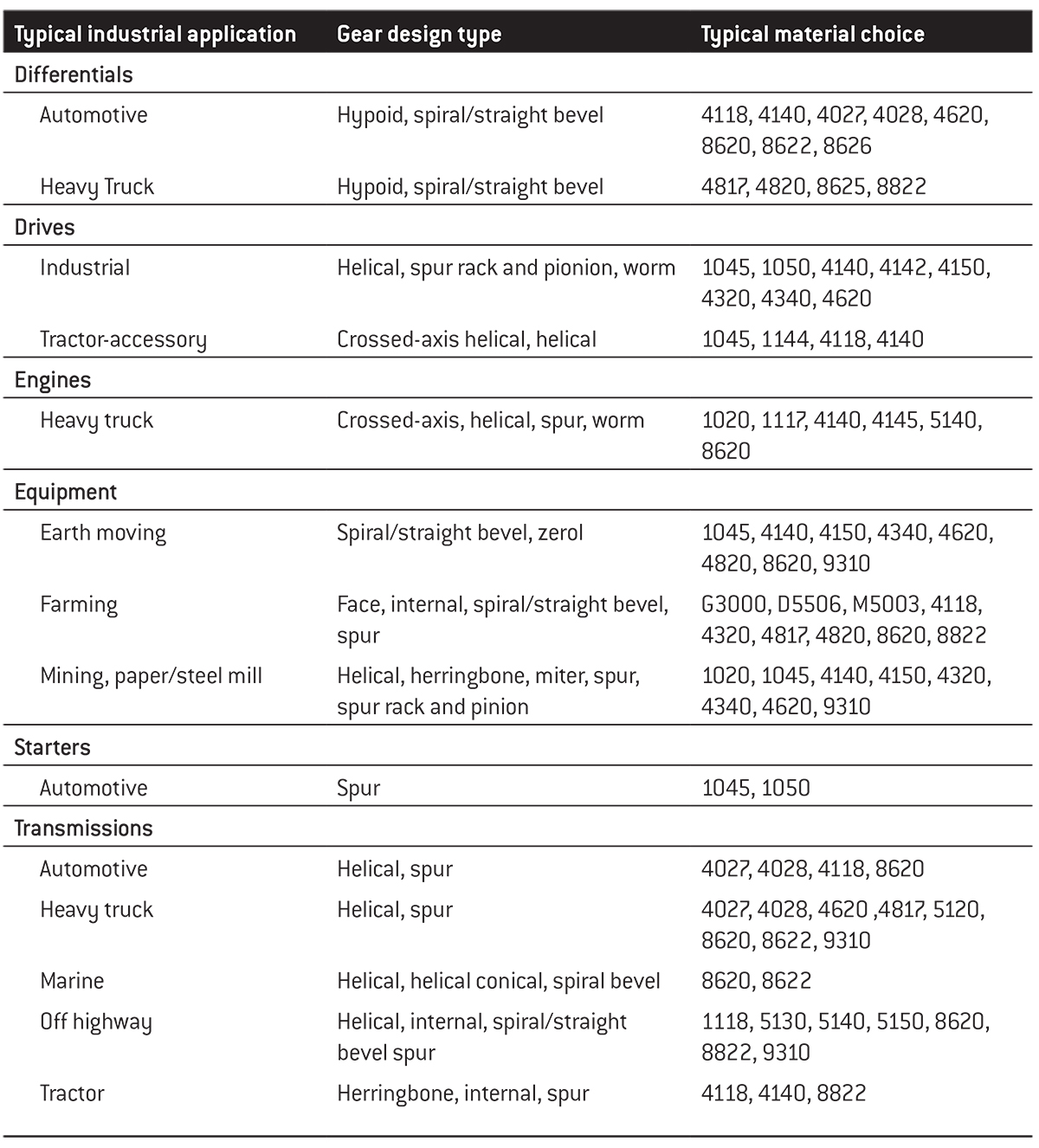
Although material represents only a small percentage (about 10%) of the cost to manufacture a typical gear, material selection must be a perfect combination of raw material cost and performance capability. Insights into the selection process can be found in Table 1 for common steels. Knowledge of the function of each of the alloying elements present in the material and their effect on the physical properties of the alloy is critical in material selection. Properties to be balanced by material selection include tensile, yield, and impact strengths, as well as elongation.
For many gear applications, core hardness, that is the cross-sectional center of the gear tooth, in the 30 to 40 HRC range is desired. To achieve this hardness, the part section size and gear pitch size need to be considered when making the selection of a material. If the core hardness is too low, it will not support the case under high load; if too high, “chipping” of the gear teeth at the case/core interface can occur.
Material selection design aids (Figure 5 and Figure 6) assist in determining the influence of part section size and gear pitch. They enable using the material’s Jominy hardenability data, which is based on the water quenching test, to yield reliable core hardness values when the material is oil or high pressure gas quenched. However, verification by testing actual samples should be done when first using these charts to confirm that the core hardness is correct.
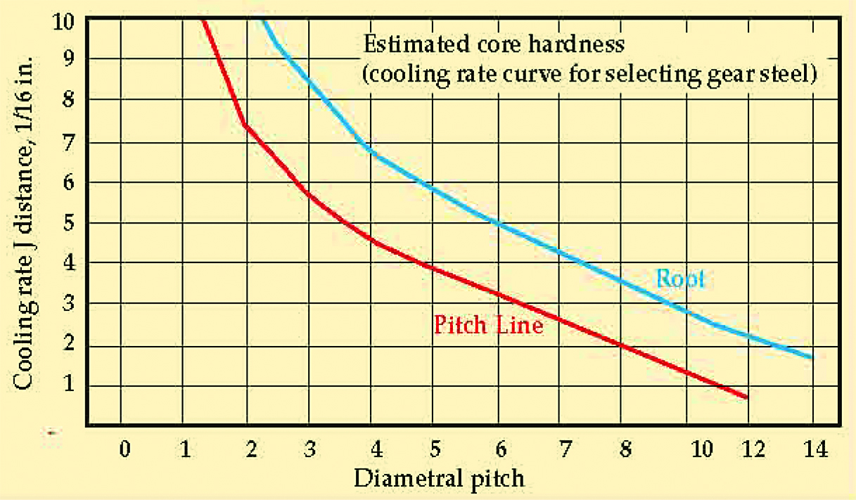
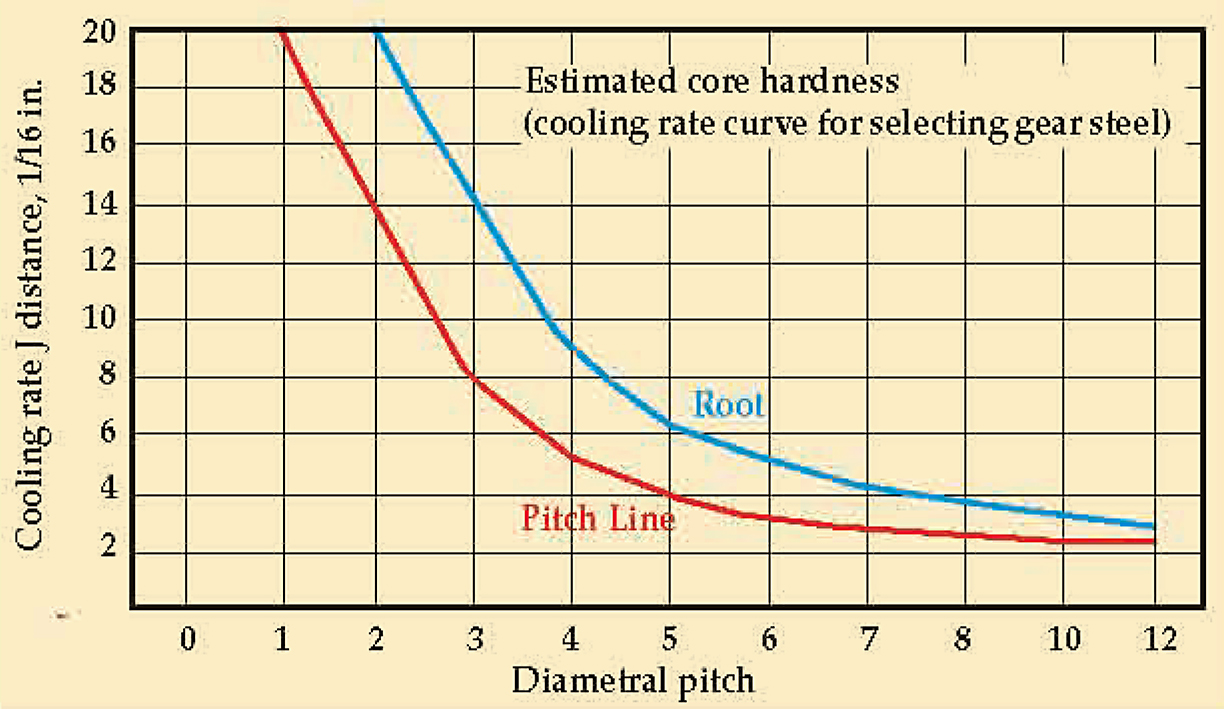
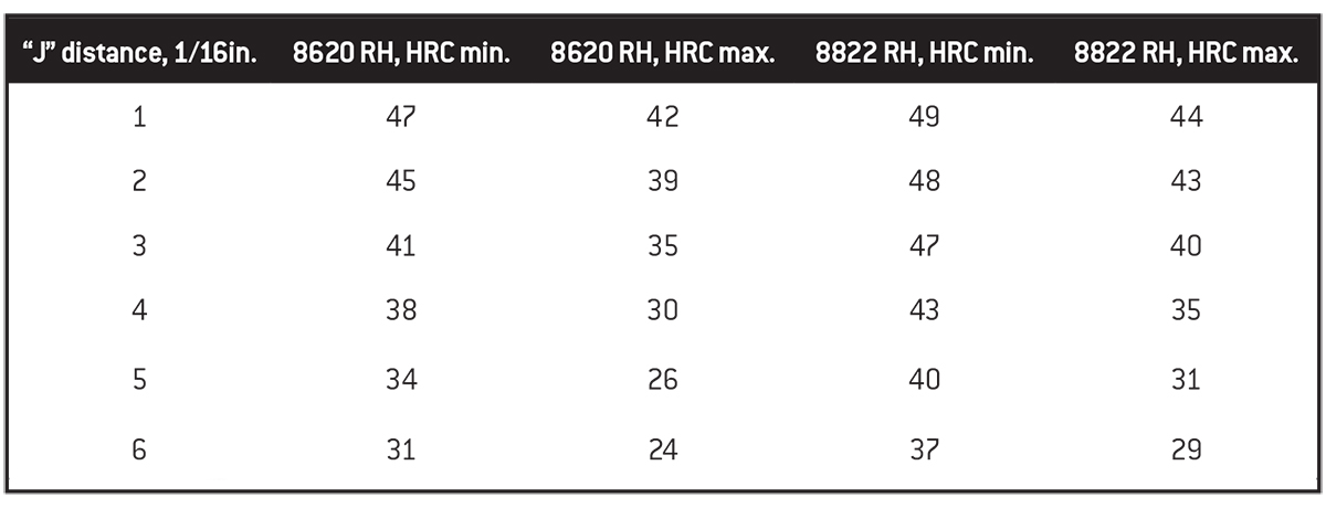
A ring or pinion gear, a typical “T” shape of four pitch size, can be used to illustrate this selection procedure. Any materials can be considered, but here two restricted hardenability materials, 8620RH and 8822RH are compared. Table 2 provides Jominy data on these steels. From Figure 5 the horizontal axis value for a diametral pitch of 4 is selected and a line is extended up to intersect the curve for the pitch line. The Jominy distance of the vertical axis is found at approximately J4.5. From Table 2, the material which best fits the desired 30–40 HRC core hardness range is selected. In this case, 8822RH is the best choice. For a 6-pitch gear, however, 8620RH material is an acceptable choice. If this gear were “solid,” the selection process would change and an alternative material could be considered.


