In this column, I will be talking about decarburization of steel and how to calculate its depth.
Introduction
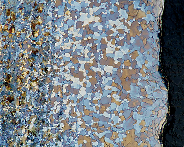
Decarburization of steel is the depletion of carbon from the surface of steel. Carbon at the surface of the steel reacts with the oxygen in the furnace atmosphere and creates CO/CO2. In an oxygen-rich atmosphere, CO2 would be formed. The oxygen also reacts with the iron in the steel to form an oxide scale. At typical heat-treating temperatures, the predominant oxide present would be FeO. An example of decarburization is shown in Figure 1.

Calculation of Decarburization
As decarburization proceeds, more and more carbon diffuses to the surface, down the concentration gradient. Since this is a diffusion problem, and exactly the opposite of carburization, the same principles apply. In this case, the case depth would be the depth of decarburization, and the surface carbon potential would be 0 %C.
The case depth is a function of time, temperature, and chemistry; of the process; and the available carbon (carbon potential) at the surface of the steel. This follows Fick’s Second Law of Diffusion for the concentration of a diffusing species as a function of time, t, and position C(x,t):
 The solution to this differential equation is:
 where C(x,t) is the concentration of carbon (in the case of carburizing) at position x at time t (s). C0 is the initial carbon content in the steel, Cs is the carbon potential of the atmosphere at the surface of the part, and D is the diffusion coefficient of carbon in austenite. The function erf(z) is called the error function and is often encountered in diffusion and heat-transfer calculations. The diffusion of carbon in austenite is [1]:
 where D is in cm2/s, R = 8.31 J/mol-°K. Using this method, the depth of decarburization can be calculated.
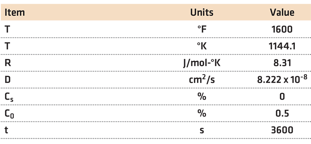
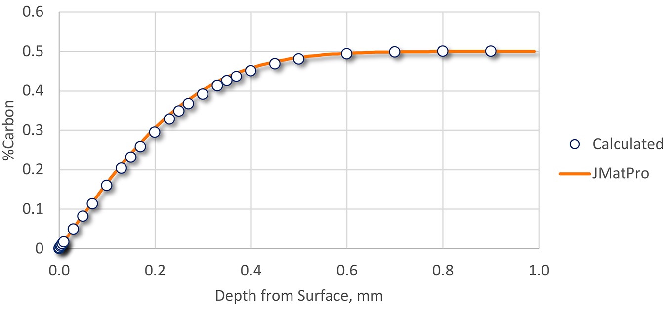
Using the data in Table 1, decarburization was calculated, then compared to data generated by JMatPro [2]. The resulting comparison is shown in Figure 2.


While the effects of alloying elements can affect the predicted diffusion coefficient, the hand-calculated and predicted profiles match very well. At least within the constraints of this calculation, the amount of decarburization can be calculated from application of Fick’s Second Law of Diffusion.
Example
Recently, a customer complained of slow hardness in their as-quenched parts. Using a medium carbon steel (SAE 5140), the parts are forged, allowed to air cool, then reheated to 850°C, held at temperature for 150 minutes, then quenched in a polymer quenchant. The parts are heat treated in air with no protective atmosphere during forging or heat treatment. After quenching, the surface is ground (with coolant), and 200 μm of the surface is removed. The hardness is then measured using a 3,000 kg Brinell hardness tester. A minimum as-quenched hardness of 470 BHN is expected. A hardness of 350 BHN has been observed.
The quenching operation is specifically designed for this operation and has adequate agitation. All pumps and agitators are working properly. The quenchant is a PVP-type quenchant, and examination of the concentration, physical properties, and the cooling curve match very well with a new quenchant. There was no apparent contamination apparent visually, or by FTIR. The quenchant condition looked to be in good condition.
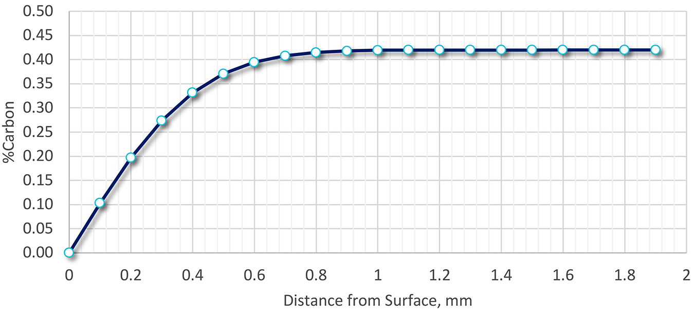
Because the steel wasn’t processed using a protective atmosphere during heat treatment or forging, decarburization could explain the low as-quenched hardness. A calculation was performed using the methodology above, and the extent of decarburization determined as a function of surface depth. The results are shown in Figure 3.

The depth of decarburization was determined to be nearly 0.8 mm deep (800 μm), or four times the amount of material removed. The carbon level at 200 μm would be approximately 0.2 percent. Assuming that the transformation to 95 percent martensite occurred, the resulting Brinell hardness would be approximately 370 BHN. This hardness is much lower than the desired as-quenched hardness but is close to the measured as-quenched hardness.
As a result of this analysis, recommendations to the customer included improving surface preparation by grinding 0.8 mm from the surface prior to taking the Brinell hardness.
Conclusions
In this column, I have shown the methodology to calculate the amount of decarburization present after heat treatment. I have also shown an example of how these calculations can be used to sort out practical heat-treating problems on the shop floor.
Should you have any questions regarding this column, or have any suggestions for future articles, please contact the editor or writer.
References
- M. F. Yan, Z. R. Liu and T. Bell, “Effect of Rare Earths on Diffusion Coefficient and Transfer Coefficient of Carbon During Carburizing,” J. Rare Earths, vol. 19, no. 2, pp. 122-124, 2001.
- Sente Software, “JMatPro,” 11 November 2018. [Online]. Available: https://www.sentesoftware.co.uk/.


