


I was once taught that heat treat is an art as much as it is a science in achieving the results required for the application of the parts. At first this was not clear, despite my academic education in material science engineering. Sure, I learned in class that nothing is perfect in accordance to textbook theory. And that not many practical situations involve sophisticated laboratory equipment and setup of highly controlled variables, but I was not fully aware why it is viewed as an art as much as it is a science until some experiences that helped shape my understanding.
This is not to say that practical situations are wildly out of control. There are still variables to be controlled in the practice such as temperature, time, atmosphere, and so on in heat treating. These variables affect the product most and customers already call them out in their requirements. However, there are other variables which also make an impact that sometimes get overlooked and need to be coordinated into the picture.
An example is how parts are racked to minimize distortion or furnace design considerations. Or the integration of the employees with the equipment. It is also beyond just the “artist’s” tools of equilibrium phase diagrams and “TTT” (time, temperature, transformation) curves that constitute the heat-treat cycle; The control thermocouple depth, power going into each zone of the furnace, and PID settings on the temperature controller are amongst additional variables.
There is a balance of theoretical and practical considerations to paint a successful heat-treatment process.
Painting 1
Theory: Why Heat Treat
As-cast properties of parts are not desirable for end use applications. Often, the microstructure needs rearrangement to produce desirable properties of the parts in service. Whether it be hardness-related or toughness of the material, common heat-treat tools to achieve these properties are the use of equilibrium phase diagrams and the TTT curves. The equilibrium phase diagram indicates which temperature ranges are most appropriate for hardening or solution temperatures and what phases are present at a given composition and temperature. The TTT curves provide insight as to quench speed requirements and cross-section ability to achieve specific microstructures to yield desired properties.
The cycles are often black and white and hardly ever change based on customer specifications proven long before I was born (I’m a millennial …). Thus, the role of the engineer today is about ensuring these requirements are met in a process that is repeatable and consistent.
Application: Workplace Culture
However, when trying to color in between the black lines, there is a balance of what is stated in the requirements compared to how it gets performed. Equipment and parts do not move without the effort of calculated and voluntary human interaction. From how the operator sets up loads to maintenance personnel working on the furnace, there are many things to consider outside of the temperature, time, and atmosphere requirements for a successful heat-treat cycle.
I realized the most important variable to realize during the workday and orchestrate into the heat-treat picture was probably that of human relations. Someone once told me that 10 percent of one’s job was comprised of technical knowledge while the remaining 90 percent was that of knowledge in interpersonal interactions.
Now, not to argue whether it’s 90.5 percent or even 9 percent, the lesson I learned was that there is an art to working with others. Often this is quickly realized in disagreements about what to do next in a problem-solving situation. If a part is distorted from, say, vacuum heat-treat, you can consider the approach of changing how it is racked, adjust the pressure quench or even the blower speed, all while making sure there is no loss in material properties. What to change first seems arbitrary sometimes and becomes more a question of what the rest of the team would want to consider first. Reducing the argon pressure or even slowing the blower down could be appealing to the operation manager wanting to reduce the cost to run after being yelled at by the owner the previous day about utility costs being high last month. Depending on who is involved on the team, and even the mood they are in for a given day, personalities can influence the decision to be made for the process.
Painting 2
Theory: Tuning the furnace temperature tolerance/The Tools
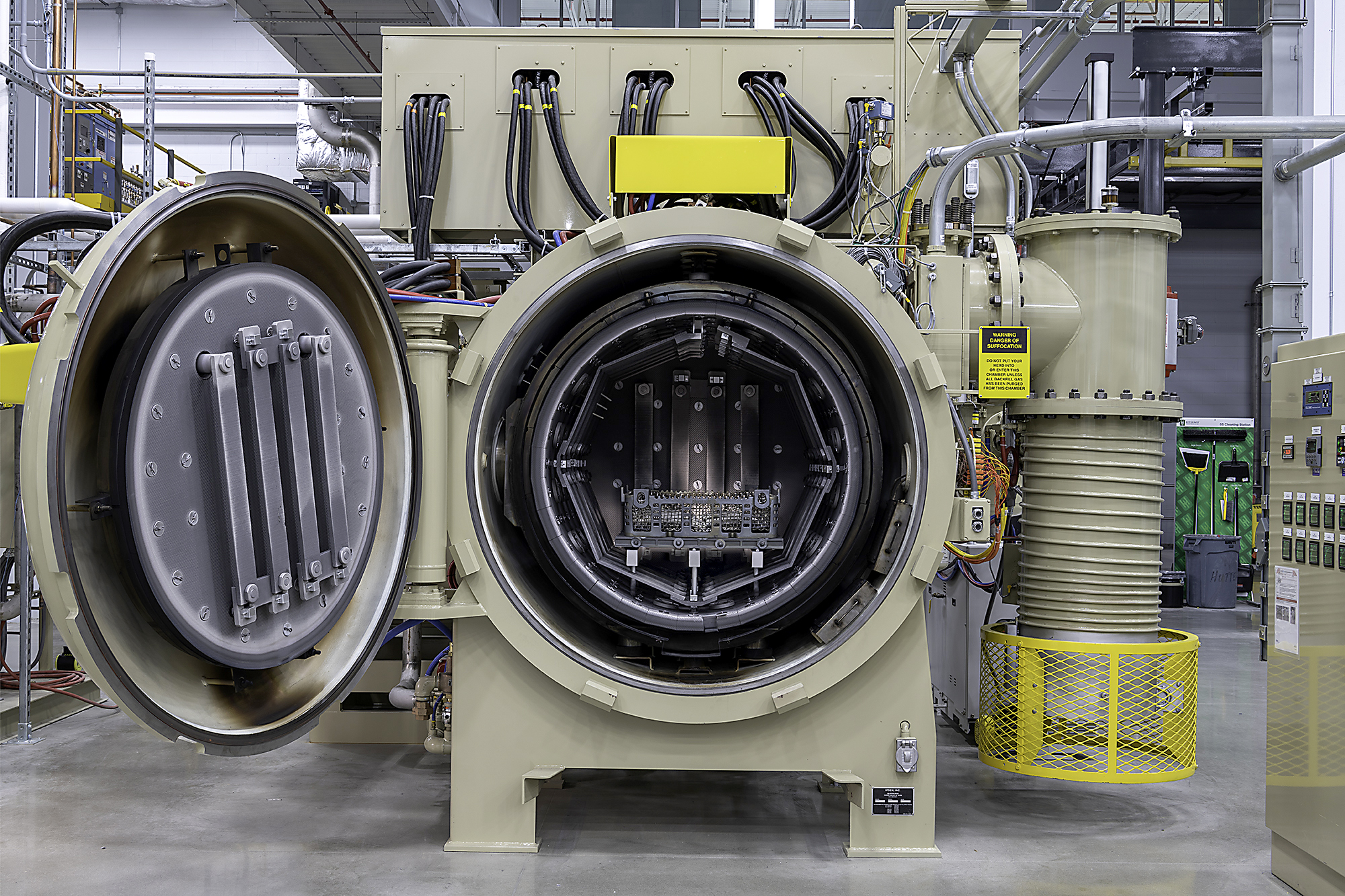
Even though today’s furnaces are built with great skill and precision to maintain temperature tolerances and control, there are still adjustments that need to be performed when a brand-new furnace has been installed. There are tools such as the ability to adjust the percentage of power into the zones of the vacuum furnace, PID settings in the controller, and the depth of the control thermocouple. These are factors to consider when performing the “TUS” (temperature uniformity survey) for the most stringent requirements of AMS2750 preventing overshoot of any thermocouple above the uniformity tolerance.
Application: Tuning the furnace temperature tolerance / The Practice
The theory says to use the tools, but the engineer must realize when best to bring each tool out. As in any experiment, it is good to control each variable one at a time to realize the effects of each. The power percentage tool could be used to tighten the temperature tolerance in each zone in a multipoint TUS. The adjustment of the load control thermocouple could move the tolerance band up or down to get it within the min and max tolerance. The PID settings could help in adjustment of the thermocouples reaching setpoint and not overshooting.
Our method of controlled changes on the new Ipsen vacuum heat-treat furnaces began with the starting point of the control thermocouple being fixed, using the same PID settings from the factory testing, and simply adjusting the percentage of power going to each zone to achieve the uniformity. One variable that was also carefully considered was the mass around the thermocouple. Since the parts were relatively thin, the use of heat sinks was not practical. In order to make the tolerance requirement, the setup was carefully reviewed to ensure a “similar mass” was around the thermocouple.
Painting the Overall Picture
Every day brings a new set of challenges, but the goal is always the same black and white requirements provided by the customer. As an artist has a vision in their mind for what they want to paint, the heat-treat engineer has the vision for how the process is to play out. The canvas is that of the workplace and the tools are beyond just the primary colors of controlling temperature, time, and atmosphere. A manipulation of other variables such as human interactions and knowledge of when to use specific tools is also required. Both theoretical and practical expectations span the palette of colors to spread with a brush across the heat-treat cycle.
Thus, you have the art of heat treat.


 general practice for CQI-9 and AMS2750E")


