


Induction hardening has become an increasingly popular heat-treatment method for steel due to its extremely fast processing speeds. Compared to other case hardening methods, the processing times are on the scale of seconds or minutes compared to hours in a carburization furnace. Typically a per-piece method, the processing speeds rival that of batch processing and, when done right, there is often no worry about scaling or decarburization due to the rapid heating and cooling. The process provides a hard, compressive surface suitable for high-wear and fatigue applications and the process can be done selectively, focusing on regions of interest instead of having to process the entire part.
Disadvantages include a higher potential for cracking and localized distortion from the high rates of heating and cooling, the initial investment cost and maintenance required for the copper coils, and reduced diffusion and carbide dissolution from the severely reduced processing times. Another disadvantage is the relatively high-tension stress state just under the hardened case, often transitioning from compression to tension abruptly in the case-core region. This abrupt change in stress can lead to internal cracking or failure in high-cycle fatigue applications such as drive shafts or powertrain components if the heat treatment is not properly designed.
Modeling the induction process becomes increasingly important as the complexity of the part and mechanical requirements increase. Induction processes are multi-physical in nature, involving electromagnetics, heat transfer, solid mechanics, and metallurgical phenomena, which lends itself well to numerical simulation through Finite Element Analysis (FEA). Simulating the electromagnetic response involves modeling the interaction between the part and the coil to obtain the magnetic field (eddy currents) that generates the joule heating within the part. This is a popular method used in coil design and initial process development but is also computationally intensive, especially when considering the thermal, mechanical, and metallurgical response of the part being modeled as well. Another useful method for modeling the induction process is to focus on the part itself and on the heat generated from the magnetic field, which is described as an internal heat generation, or flux, in the elements that define the case. This method is less intensive computationally as the coil itself is not modeled and is most useful when the profile that the coil produces is well-known and small changes in part geometry or heating recipes are to be explored. In general, power regulates the amount of heat that is provided to the part and is highly dependent on the surface area being treated. The frequency of the inductor controls the depth of the case, with lower frequencies increasing depth and higher frequencies providing a shallower case. For the flux method, the profile generated by the frequency can be described by a flux profile based on the depth from the surface, typically starting high at the surface and dropping sharply with increased depth. Once developed and validated, the FEA models can be used to modify and optimize the residual stress profile of a part through process modifications, such as applying a preheat step prior to hardening.
Case study
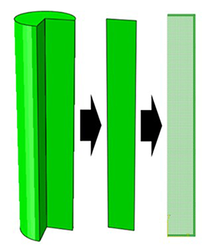
Finite element models were developed for two example single-shot induction hardening processes. The geometry consists of a three-inch diameter shaft, made from normalized AISI 4140 steel, which is modeled with axis-symmetry along the longitudinal and radial axis and meshed with 3358 elements and 3528 nodes (Figure 1).
The case depth is between 1.5-2mm, and the as-quenched hardness is required to be above 55 HRC. The example heat-treatment schedules for the induction processes include:
- Single-shot recipe
- Induction heating at full power for 6.5 seconds.
- Spray quenching for 60 seconds.
- Air cool to room temperature.
- Preheat recipe
- Induction preheating at 1/10th power for 60 seconds
- Induction heating at full power for 3 seconds
- Spray quenching for 60 seconds
- Air cool to room temperature
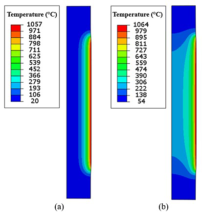
The modeling assumptions include a constant frequency, or flux profile, for both processes while only the power is adjusted. Heat transfer boundary conditions include convection coefficients for hot air during induction, water spray during quenching, and still air for the final air cool. Radiation was not modeled to simplify the analysis. Figure 2 shows the simulated temperature profile in the shaft for both the processing conditions after induction heating, just before spray quenching. The single-shot model shows a room temperature core while the preheat model shows the core to be about 250°C, while the surface temperatures for both the models are about 1,060°C.
The sequential thermal and stress models were executed using Abaqus standard and DANTE material models on a standard laptop, using four cores of an Intel i7 processor. Each analysis was complete in under one minute. For post-processing, path plots were taken from the mid-height of the axis, from the surface to the core, to avoid any end effects from heating or cooling.
Results
The results of the executed models show a surface hardness of about 56 HRC and matching case depths and hardness profiles (Figure 3). The case depth, as measured at 50 HRC, is shown to be about 1.8mm from the surface. At roughly 2.5-3mm from the surface, the hardness drops to the annealed core values, just below 30 HRC.
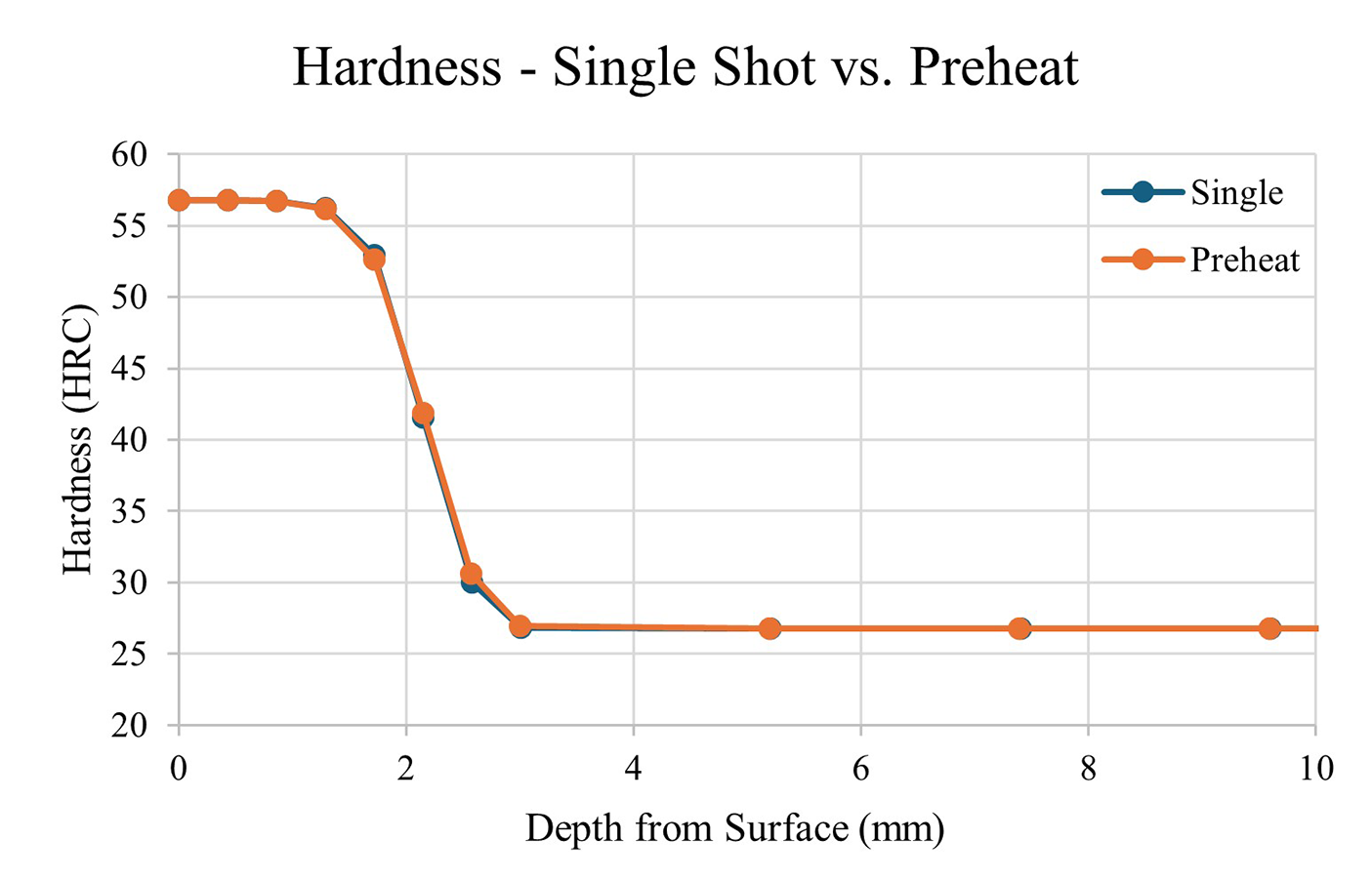
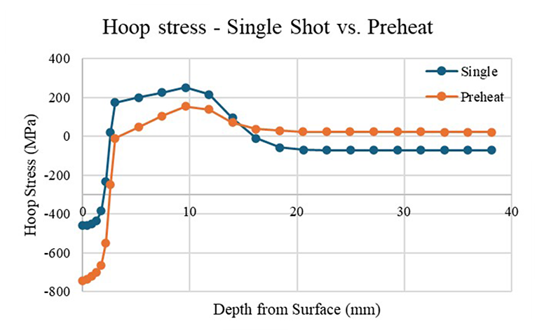
The sharp drop in hardness at the case-core interface is caused by the austenite to martensite transformation in the case. The volume expansion caused by this transformation is often the cause for concern with respect to residual stress. The larger martensite phase leads to compression in the case, but also pulls on the material just below the case, causing residual tension. Figure 4 shows the residual stress profile in the hoop direction, circumferential, after the spray quench and air cool steps. The single-shot process produces a surface compression of about 450 MPa, while the preheated model shows higher surface compression with a magnitude of about 740 MPa. The preheated model also shows a decrease in residual tension just under the case compared to the single shot model. At three millimeters, the preheated model is relatively neutral while the single shot model shows about 170 MPa of tension. The preheated model continues to show a reduced magnitude of compression until about 14mm from the surface, where the model shows slight tension to the core and the single-shot model shows slight compression to the core.
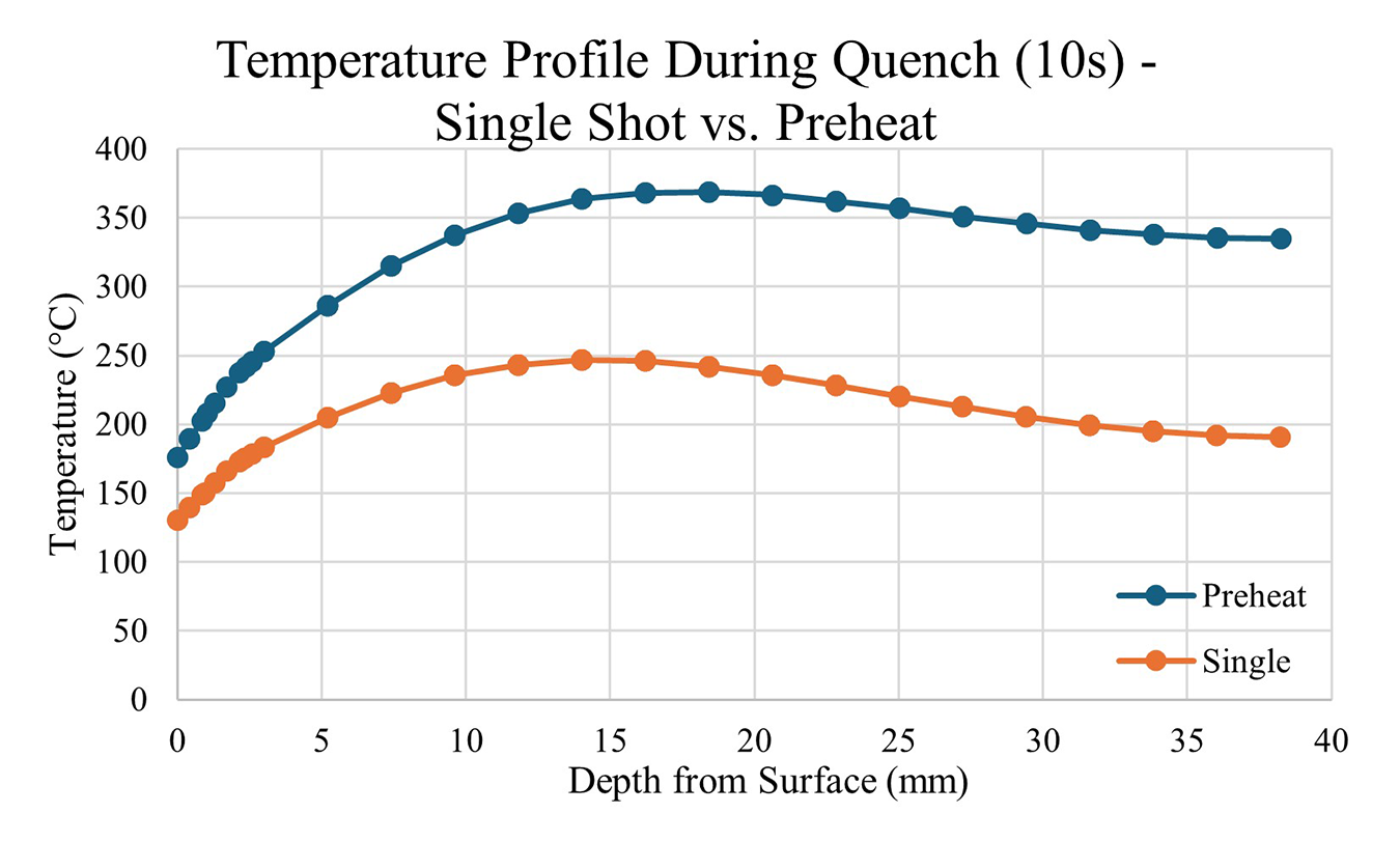
The mechanism that causes the higher magnitude of compression in the case, and reduced case-core tension, with the preheated model can be understood through thermal expansion. Both models form the same amount of martensite in the case; however, the core of the preheated model is warmer, and therefore larger, than the cool core of the single shot model. The preheated shaft shrinks after the case is formed, inducing compression throughout the part as the core is finally cooled to room temperature. Figure 5 shows this temperature difference after 10 seconds of quenching time, where the martensite transformation is complete for both models.
Conclusions
The induction-hardening process is a contactless and effective process for case hardening steel. The short process times and advancements in automation improving consistency allow for quick and reliable results. Residual stress is a concern due to the sharp transition from compression to tension at the case-core interface. The FEA models have been used to tailor the stress profile as required by preheating to increase surface compression and reduce the magnitude of tension at the case-core interface. Simulation is effective in testing new processes and viewing the part response to new methods before running physical trials.


 general practice for CQI-9 and AMS2750E")


