


In flight, aerospace components are in a state of constant cyclic stress. The term “flying fatigue machines” is commonly used by those in the industry for a good reason. The dynamic forces planes and helicopters experience during service, while hopefully well below the yield strength of the material, require attention to potential fatigue-related issues during the design stage. The tiniest crack can be propagated by fatigue into a major failure.
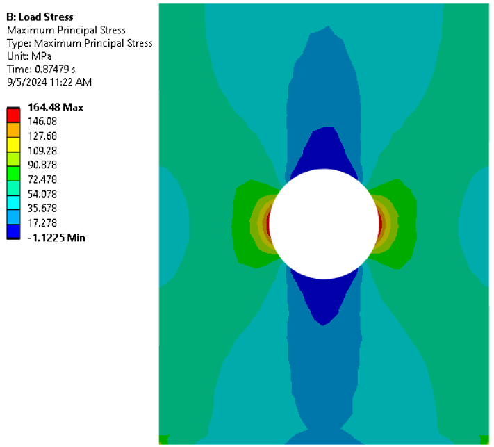
There are several ways to reduce the risk of fatigue failure, including modifying component geometry to reduce stress concentrations or by surface treatment. In modifying part geometry, it is important to keep in mind that these components are required to be as lightweight as possible. Strengthening the material is another valid option to combat fatigue without increasing part weight. Structural components in planes are often held together with rivets or bolts, requiring holes to be drilled or punched before the fasteners can be applied. These holes act as concentrators to any stresses that are developed in service. Figure 1 shows a classic example of stress concentrations around a hole in a plate which is loaded axially. Notice the tension at the 3 o’clock and 9 o’clock positions, and the compression in the 12 o’clock and 6 o’clock positions from the vertical load. In service, these stresses will cycle the edges of any hole through tension and compression, and any micro-cracks or defects around the edges of the holes will eventually lead to crack propagation and failure.
The most common and effective way to reduce the effect of fatigue on the fastener holes is to cold work the material, inducing compression along the inner edge of the hole, in a process called cold expansion. In cold expansion, the hole is produced undersized and widened to the required dimensions, inducing a layer of compression around the hole from the subsequent elastic response of the surrounding material as it attempts to return to the undeformed state.
There are several common methods for widening the holes. One method uses a lubricated mandrel that is pulled through the hole, and another uses a ball that is pushed through the hole. Both methods provide a directional burnishing effect from the frictional forces on the inner surface, potentially producing undesired tension on the leading edge of the hole. A better approach uses a mandrel and a split-sleeve as a buffer between the mandrel and hole, and the split sleeve is simply discarded after the process. This method allows the force of the mandrel to be directed radially, thus having a more uniform radial deformation while removing the axial frictional forces from a mandrel-only process. The split in the sleeve does leave behind a small pip which must be removed after the process.
The level of compression achieved by the cold expansion process depends on the amount of expansion and the yield strength of the material. For example, a quarter-inch diameter hole widened 3 percent would produce a hole 0.2575 inches in diameter. The elastic-plastic response of a workpiece undergoing a cold expansion process, along with the contact behavior between the mandrel and split sleeve, can be simulated using nonlinear finite-element analysis. Using simulation, engineers can ensure the required magnitude and depth of compression is achieved.
Case study
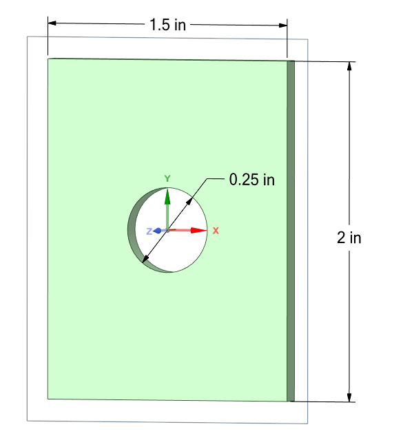
A case study has been developed to explore the cold expansion process and to quantify the magnitude and depth of compression achieved. The geometry for the FEA model includes an eighth-inch plate with dimensions shown in Figure 2. The quarter-inch hole in the center of the plate will be expanded by 3 percent and 6 percent, over two seconds, to explore differences in magnitude and depth of compression achieved by each process. The plate is made from aluminum alloy 6061 in the T6 temper condition. DANTE’s material and elastic-plastic model, based on the Bammann-Chiesa-Johnson (BCJ) model, will be used to solve the material response as the BCJ model is well-suited for high strain-rate applications. To save computational costs, the mandrel will not be modeled. Instead, the inner surface of the hole will be expanded uniformly in the radial direction to model the deformation using a cylindrical coordinate system centered on the hole. The resultant hoop stress will be reported along the midplane of the plate.
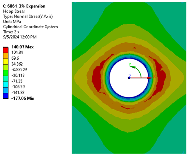
The hoop stress contour and coordinate system for the 3 percent expansion model are shown in Figure 3. The contour shows the achieved compression in the range of 22 ksi (~170 MPa) which falls off with depth from the inner surface of the expanded hole. Surrounding the compression, a layer of tension exists to satisfy the stress equilibrium within the plate. This tension is lower in magnitude but covers more area within the part than the compressive case. The stress away from the hole is not circumferentially uniform because the plate is rectangular in this model.
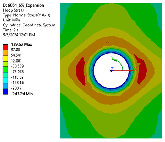
The hoop stress contour for the 6 percent cold expansion model is shown in Figure 4. The achieved magnitude of compression for this model is higher than the 3 percent model, about 34 ksi (240MPa), which is closer to the reported yield strength of 6061-T6 aluminum. The magnitude and area of tension surrounding the compressive case is comparable to the 3 percent expansion model.
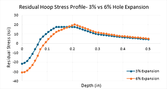
A path plot was developed to compare the residual hoop stress for each of the two processes. The path is taken from the midplane, along the X-axis, from the inner surface of the hole to the right edge of the plate, as shown in the previous contours. Figure 5 shows the collected stress values converted to ksi units. The plot shows good compression in the inner surface of both models, with the 6 percent model showing a higher magnitude. The depth of compression is also greater in the 6 percent cold expansion model. The 3 percent expansion model transitions to tension at about 0.075 inches, while the 6 percent expansion model transitions to tension at about 0.1 inches. The predicted level of tension surrounding the case is comparable for both models with a slightly higher peak magnitude that is deeper for the 6 percent model.
Conclusions
Cold expansion is a quick and efficient method for strengthening the material around fastener holes for aerospace applications without adding weight. There are several different methods for cold hole expansion, but they all aim to provide compressive residual stress through plastic deformation and elastic recovery. The imparted compressive stress from the process increases fatigue life by offsetting tensile loads that form at the stress concentrations near the holes. The residual compression reduces the early onset of fatigue crack initiation near the surface. The process was successfully modeled with two levels of deformation, 3 percent and 6 percent expansion, to compare the resulting hoop stress. The hoop stress contours show the 6 percent expansion model results in a higher magnitude of compression and deeper case than the 3 percent model. The results of these models can be further used in loading models to ensure the depth and magnitude of compression is sufficient for the application, or to predict the stress balance from final machining. In the ever-expanding world of aerospace applications, engineers using simulation can fill in the holes from production and ensure you are not left out in the cold.


 general practice for CQI-9 and AMS2750E")


