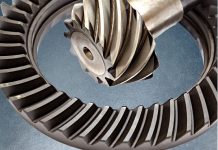
Heat treatment is a critical and complex element in the manufacturing of gears that greatly impacts how each will perform in transmitting power or carrying motion to other components in an assembly. Heat treatments optimize the performance and extend the life of gears in service by altering their chemical, metallurgical, and physical properties. These properties are determined by considering the gear’s geometry, power transmission requirements, stresses at different points within a gear under load, load cycling rates, material type, mating part designs, and other operating conditions. Heat treatments improve physical properties such as surface hardness, which imparts wear resistance to prevent tooth and bearing surfaces from simply wearing out. Heat treatments also improve a gear’s fatigue life by generating subsurface compressive stresses to prevent pitting and deformation from high contact stresses on gear teeth. These same compressive stresses prevent fatigue failures in gear roots from cyclic tooth bending. Physical properties such as surface hardness, core hardness, case depth, ductility, strength, wear resistance and compressive stress profiles can vary greatly depending on the type of heat treatment applied. For any given type of heat treatment the results can be tailored by modifying process parameters such as heating source, temperatures, cycle times, atmospheres, quench media, and tempering cycles to meet specific application requirements.
Besides selecting heat treatments that will produce a set of desired physical properties, manufacturing engineers want to minimize distortion of dimensions from treatment such that final proper fit into a gearbox can be achieved. Many gears are machined into an oversized condition prior to heat treatment so that a planned amount of grind stock may be removed after the process in order to meet dimensional requirements. By selecting heat treatment processes where distortion is reduced, the amount of grind stock needed may be reduced to minimize machining on hardened surfaces after heat treatment and thereby reduce the overall costs of manufacturing. Removing too much of the outermost portion of a case hardened gear that distorted excessively will also negatively impact the fatigue properties and wear life performance. Some heat treatment processes are designed to treat the entire surface of a gear, while others are selective in nature. Induction hardening or selective heating may be employed to harden just the gear teeth only, which can be an effective method of reducing the distortion in a gear. Masking of journals and keyways may be employed in case hardening processes to keep them soft and allow for easier grind stock removal after heat treatment. Reduction of distortion by intelligent heat treatment process design allows manufacturing engineers to improve the performance and/or reduce the overall costs of manufacturing a gear.
In all cases, gear design engineers understand that heat treatments play a complex and vital role in both the ease of manufacturing and the performance of the gears they make. Today, many options exist for the heat treatment of gears. Proper selection and design of the heat treatment process can greatly affect performance, ease of manufacture, and economics of a component. This paper will focus on a variety of different processes and highlight some benefits and disadvantages of each.
Heat Treating Basics
To understand heat treating, a basic knowledge of metallurgy is needed. Iron, when combined with small percentages of carbon, forms steel. Plain carbon steels typically contain 1 percent or less carbon in combination with iron. The maximum hardness that any plain carbon steel can achieve during heat treatment is primarily a function of its carbon content. Higher carbon content steels are capable of being hardened to higher hardness values than lower carbon content steels. To make alloy steels, small percentages of other elements such as Cr, Ni, Mo, Si, B, V, Ti, Al, N, Nb, W, and Cu (to name the most common) are added to steel. These alloying elements are added in order to increase hardenability or enhance specific properties such as toughness or resistance to softening from heat build-up. For heat treaters the higher hardenability allows for slower quenching, which means distortion can be kept to lower levels in more highly alloyed steels. Steels can be annealed by thermally processing at a high temperature and slow cooling to soften it. In this soft and malleable state it can be machined, formed, hobbed, and ground easily into a desired shape. What makes steel industrially important is that it can be hardened after the material has been formed or shaped in the soft state to a desired geometry. By use of a thermal processing cycle where steel is heated to austenitizing temperatures and rapidly quenched, the near-finished components can be hardened to improve wear resistance, strength, and hardness. After quenching to the maximum hardness achievable, which is determined by the steel’s carbon content, the steel may then be tempered down to a lower hardness to improve ductility and toughness at the expense of slightly reducing the strength, hardness, and wear characteristics of the material.
What actually occurs in steel during heat treating are phase transformations as atoms rearrange themselves into different crystal structures. The starting point of most heat treated parts is an annealed material. In fact, when purchasing steel it is generally in the annealed condition. An annealed structure is a combination of primarily ferrite (Fe, pure iron) and iron carbide (Fe3C, cementite). These will be in the form of alternating layers of ferrite and Fe3C (pearlitic structure), or ferrite with dispersed Fe3C spheres or spheroids (spherodized structure). When steel is heated above its austenitizing temperature, it transforms into the austenite structure. An approximate austenitizing temperature for most plain carbon steels is around 1330ºF and varies by exact grade of steel. Once full transformation of the steel to an austenite structure has occurred the austenite may be quenched (cooled rapidly), and that austentite structure will transform to a martensite structure. This transformation of austenite to martensite is the hardening process. The martensite structure yields the highest hardness and tensile strength properties of any structure for that steel. Producing a martensitic structure from austenite is the goal in hardening heat treatment of steels. One critical aspect of this hardening process is the cooling rate employed during quenching. Each grade of steel requires that a certain minimum cooling rate be achieved during quenching or the transformation from austenite to martensite will not occur. Austenitized steels held at high temperature and quenched too slowly down to ambient temperature will not transform from austenite to a martensitic structure. They will instead revert back a softer mix of ferrite and cementite again.
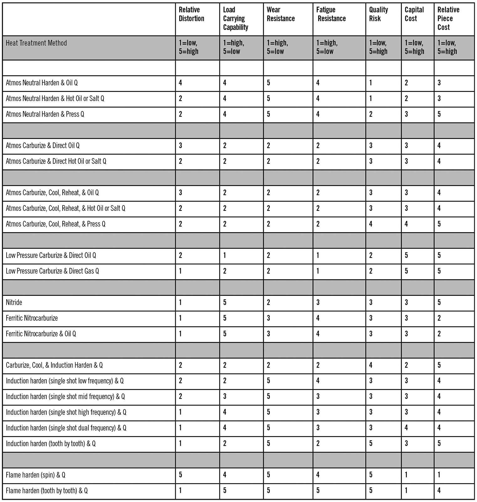
Table 1 summarizes the methods in common use today for heat treatment of gears. Each method has its place; some are perfect for high volumes, while others are practical only on a piece-by-piece basis. Some improve all metallurgical properties, while others improve only one or two.
Neutral Hardening
There are two general classifications of heat treatments used for hardening steels: neutral hardening, and case hardening. Neutral hardening refers to maintaining the carbon potential of the atmosphere at the same percentage as the carbon in the steel during the hardening cycle. This means that carbon is entering and leaving the surface of the steel at the same rate, and no net gain or net loss of carbon atoms inside the surface of the steel occurs. Many gears are neutral hardened, but for the most demanding applications case hardening processes, such as carburizing and nitriding, are the preferred methods due to their improved wear characteristics and mechanical properties.
Atmosphere Carburizing
Carburizing, the most widely used form of surface hardening, is the process of diffusing carbon into the surface of low carbon steel at elevated temperatures. This results in a high carbon case forming just inside the surface of a low carbon component. During quenching from austenitizing temperatures the austenite will transform to martensite, and the higher carbon case will have a high hardness while the lower carbon core material will have a lower hardness. The goal of this process is to produce a hard, strong, wear resistant outer surface while retaining a softer, ductile tough core.
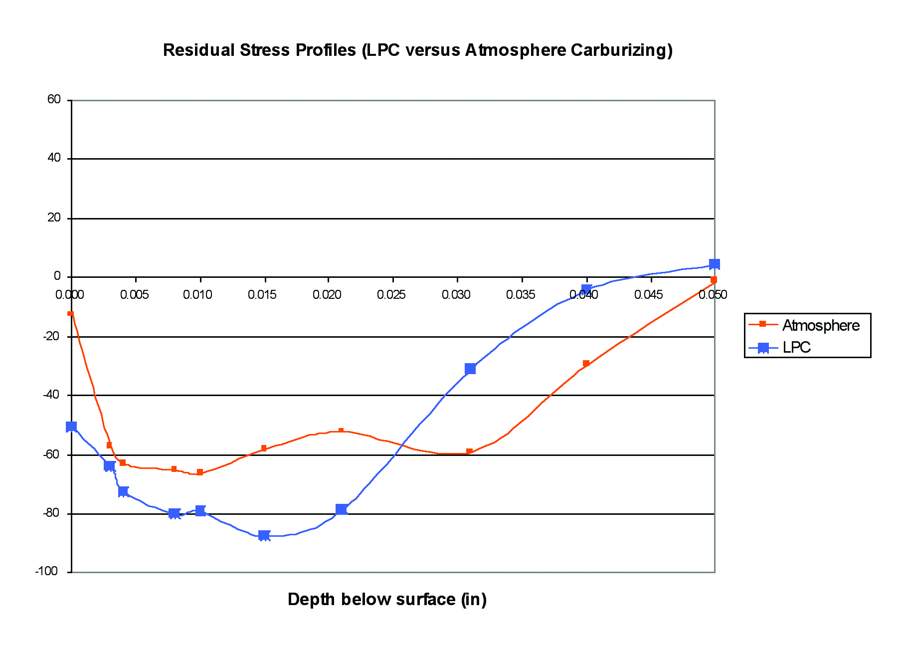
When austenite transforms to martensite during quenching, a volume expansion occurs in the material and it grows. The volumetric expansion in the case is greater than the volume expansion in the lower carbon, lower hardness core structure. This difference in size changes puts the carburized surface of the part into a state of compression, which makes it stronger. For example, when a force is applied to a gear tooth, it first has to overcome these compressive forces before beginning to put the surface of the tooth in tension. In order to deform this material, it requires a force that exceeds the combination of overcoming the compressive stresses present in addition to the normal yield strength of the material. These compressive stresses caused by differences in volume expansion rates between the case and core improves the overall tensile and yield strength of the carburized case inside a gear tooth. It is these compressive stresses that resist deformation from high contact stresses present as gear teeth press and roll against each other. These compressive stresses also increase fatigue life by helping to prevent cracking in tooth roots as the teeth are cyclically loaded and unloaded with bending stresses. The high carbon, high hardness surface of the carburized case also resists wear and scoring caused by friction as gear teeth rub and wear against each other.
One can’t discuss heat treating gears without discussing distortion, which occurs for a variety of reasons. One source is pre-existing residual stresses present in the material caused by prior operations such as steelmaking, rolling, forming, forging, casting, machining, and grinding. As the material begins to heat up during carburizing, these residual stresses present in the material relieve and cause the gears to distort if these stresses were large or non-uniform.
A second source of distortion is high temperature creep during processing. Gravity is the enemy of many gear designs during thermal processing, especially in carburising, where high temperatures and long processing times are the norm. At high temperatures, steel has little strength and can sag and bend under gravity’s force if sections of a part are not properly supported or components not stood up or hung perfectly straight. Spending the extra time to fixture parts correctly and designing customized fixtures to properly support a gear during exposure to high temperatures can save many hours of straightening and machining afterwards. Some part shapes such as long shafts are best racked in vertical orientations to maintain straightness while other shapes such as rings are better if laid flat horizontally to maintain roundness. Selection and experience in designing heat treatment fixtures can dramatically affect the results.
A third source of distortion is quenching, which is typically the main offender in distorting parts during heat treatment. The ideal quench is the slowest quench that will uniformly pull heat out of the part, while still fully transforming the surface to martensite and achieving the desired case and core properties. This sounds easy enough, but in practice it can be quite difficult given the design and complex shape of many gears. Due to variations in customers’ part geometries, limitations in fixture designs, non-uniform quench tank agitation, and part-to-part or part-to-fixture interactions, it is the most difficult distortion mechanism to resolve and predict. Even within a single part it’s possible to have some thinner sections of a component cool faster than thicker sections causing one area to transform earlier than another and warp dimensions as the transformations with their associated volume expansions occur at different times during a quench.
When distortion occurs to an unacceptable degree, solutions need to be found. After exhausting all the variations of processing parameters, fixturing methods, quench modifications, and ensuring parts are free from stress prior to heat treatment, other options need to be considered. This can be as simple as a straightening step, or as difficult as re-engineering the part. Some other methods of heat treating may provide more effective solutions to reducing distortion as well. Processes such as press quenching, tooth to tooth induction hardening, vacuum carburizing with gas quenching, and nitriding are employed when excessive distortion results during conventional carburizing of specific gear geometries.
Press Quenching of Gears
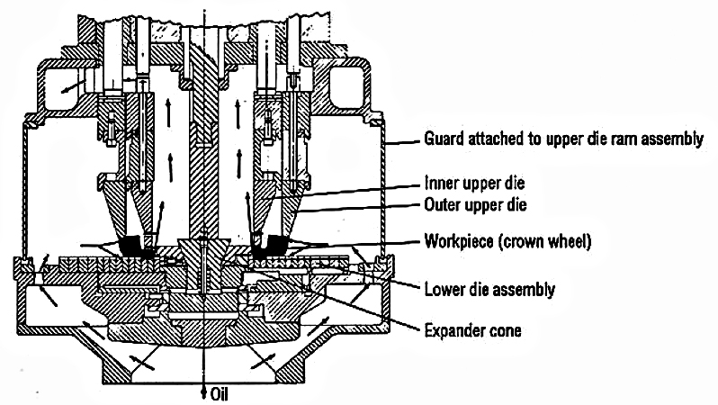
The art of press quenching while being around for decades remains somewhat of a mystery to the engineering world, and even our own heat treating industry. In basic form, gears are carburized in large batches, slow cooled, reheated individually, and then quenched rapidly under some form of restraint to minimize distortion. The main dimensions that are restrained during press quenching are the flatness of the gear and the roundness of the bore in relation to the hub.
The quenching equipment utilized is referred to as a press. They are either pneumatic or hydraulic in design, depending on the individual piece of equipment. The press has a lower die assembly that floats in nature and becomes stationary during the quench process. The upper die uses a primary and secondary upper pressure system that has two levels of controls through an outer and inner cylinder assembly. Depending on the press being used the maximum die pressure is different.
When the gear is transferred to the press and placed on the die for quenching, it is restrained through the use of tooling designed specially for the gear being quenched. Oil flow becomes critical to the success of the pressing operation to minimize any distortion. The oil flow comes up from the oil reservoir through the chambers or holes within the lower die assembly, then circulating up and around the table to the oil flow rings based on the lower die table. The oil flow can be controlled through the manipulation of oil flow rings, which are located underneath the support rings. The oil flow can be restricted or wide open depending on the gear being quenched. This flow is regulated through timer controlled valves. The inner cylinder force is exerted against the rim of the gear to address flatness while the outer cylinder can be used to apply pressure to the face of the hub or to apply pressure to expand out an expander mandrel in the attempt to control the spline or bore sizing.
Whether a plug or an expander is used in a bore depends upon what is trying to be accomplished. An expander is employed when the heat treater is trying to expand the tooling out to meet an intended bore diameter prior to the actually quenching the part. The intent is to minimize any “out of round” conditions that may occur. Larger bore diameter gears with thin wall thicknesses are prime candidates for the use of an expander to prevent any out of round conditions. A plug is used for holding a bore dimension. The plug is ground to a size close to the intended bore diameter. The heat treater is trying to have the bore cool or shrink uniformly to a certain dimension. A finish grinding operation of the bore is usually performed after plug quenching.
The focus on gear press quenching should not be on the use of tooling. It has been taught that the best gear starts with the gear blank. Addressing the forging operation for the gear blank is important. In the forging operation, the direction of the grain pattern is critical such that the part will not have non-uniform residual stresses present. It is important that the blank also be normalized or annealed at temperatures that exceed the planned carburizing temperature by 50ºF. It is also important to ensure that the cycle time at temperature is held for a proper length of time. Insufficient time or temperature during normalizing or annealing will result in greater distortion being present during subsequent heat treatment steps. It is often recommended to perform a subcritical stress relieving operation after the rough machining of the gear blank to help minimize distortion in the final heat treating operation. While not considered absolutely necessary, it does help reduce distortion and improve the final quality of the part.
Another concern that comes up in gear hardening is the tapering of the bore diameter through the length of the bore. This arises due the sectional changes present in some gears along their axis. The use of an expander and using various pressures on the inner cylinder will result in minimizing tapering. Tapering cannot be eliminated in some gear designs, but it can be minimized.
When designing gears where press quenching is planned, it is recommended to have the heat treater involved from the design stage to understand how it will affect the final product. Press quenching is not the lowest-cost hardening process available, but it is a competitive process among today’s gear hardening processes. In many cases press quenching is the only option, as distortion from conventional carburizing and quenching processes can be too excessive on some sensitive gear geometries.
LCP/High Pressure Gas Quench
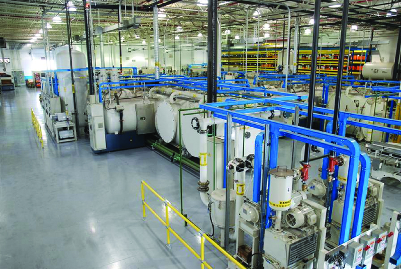
Low Pressure Carburizing (LPC) with high pressure gas quench is a relatively new carburizing technology that has become more widely used during the last decade. It has become the popular choice of carburizing treatment for automotive transmission gears over the last 10 years with General Motors, Ford, Chrysler, and many foreign automakers now adopting this process. Many fuel injectors are currently carburized using this technology. Some aerospace components are also being low pressure carburized, with rotorcraft transmission gearing being another early adopter of LPC. Figure 7

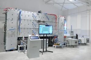
LPC equipment comes in a variety of forms from different furnace manufacturers that all have different concepts and designs. In general, the equipment consists of vacuum chambers capable of heating parts to carburizing temperatures and capable of injecting small amounts of hydrocarbon gases at low pressure that act as a carbon source. In addition to the carburizing cells there are quenching cells where carburized hot loads may be cooled using high pressures of inert gases to rapidly cool the parts allowing hardening to occur by transforming austenite to martensite in the case and core structure. The gas quench cells are equipped with powerful fans and are capable of injecting gases typically up to 20 bar positive pressure in conjunction with heat-exchangers using chilled water to quickly remove heat from the quenching gases. The most common quenching media is high pressure nitrogen gas, and the more common carburizing gases are propane and acetylene. Many furnace manufacturers are using different gases, however, and blends of gases as carbon sources and quench gases.
High hardenability alloys are required for LPC and high pressure gas quench. Typical grades of materials used are 8620, 5120, 4118, 17CrNiMo6, 9310, 3310, 8822H, 4822, and 8630. Lower hardenability plain carbon steels that can be carburized and oil quenched simply cannot be hardened using a gas quench because they will not properly transform as cooling rates are too slow. Even with high hardenability grades some consideration must be given to core hardness, as the gas quench will produce lower core hardness compared to oil quenched parts.
A major advantage of LPC is that these same slow cooling rates during gas quenching translate into low distortion from quenching. Many parts that cannot be successfully oil quenched and maintain required dimensional tolerances are able to be LPC processed with a gas quench and yield acceptable dimensions. By eliminating the non-uniform cooling of parts associated with liquid quenches that have vapor, boiling, and convective cooling all taking place simultaneously and replacing it with gas quenches that have slower cooling rates and are more uniform and purely convective, distortion can be greatly reduced as gear surfaces are more uniformly cooled at slower rates. LPC with gas quenching can sometimes eliminate post-heat treatment straightening or clamp tempering operations, reduce grind stock allowances and hard machining, or replace more costly processes such as press quenching of individual gears.
A second advantage of LPC is cleanliness of the parts after processing. The finished parts emerge from the furnace very clean. At times it is almost difficult to identify the heat-treated and non heat-treated parts. For this reason the heat-treated parts are slightly discolored, using the discoloration process to identify the heat-treated parts. In comparison, conventional carburizing uses oil quenching where the oil will burn onto the surfaces and finished parts are often dark, sooty, and have oil residue left on the surfaces.
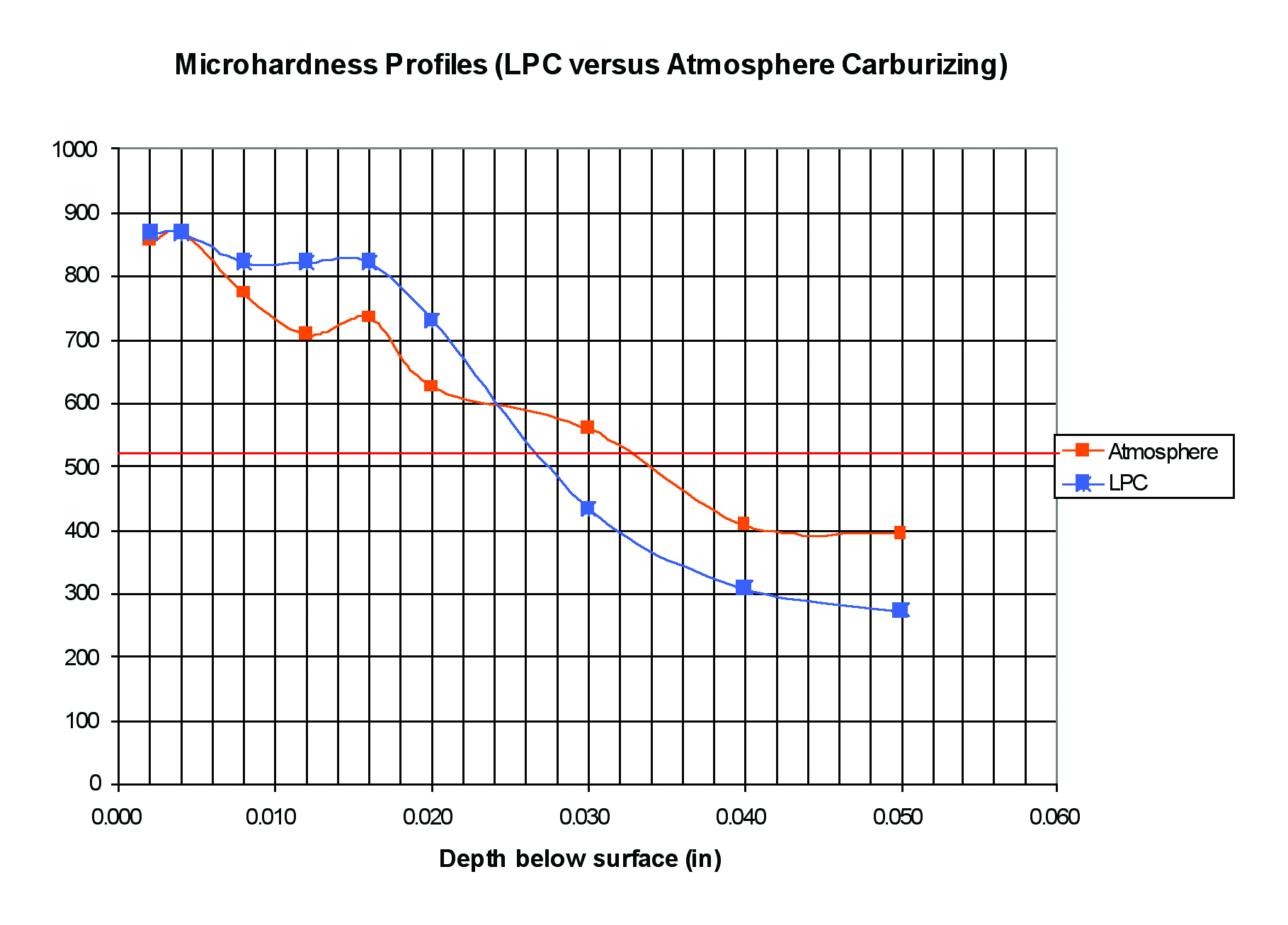
Another advantage of the LPC process is that it has the capability to utilize a higher carbon potential atmosphere during the boost thus obtaining higher hardness values deeper into the case in comparison to the conventional carburizing. This higher hardness deeper into the surface before transitioning to the core imparts greater compressive stresses to the surface case material and improves the fatigue properties and resistance to deformation by high single point rolling contact stresses on gear teeth.
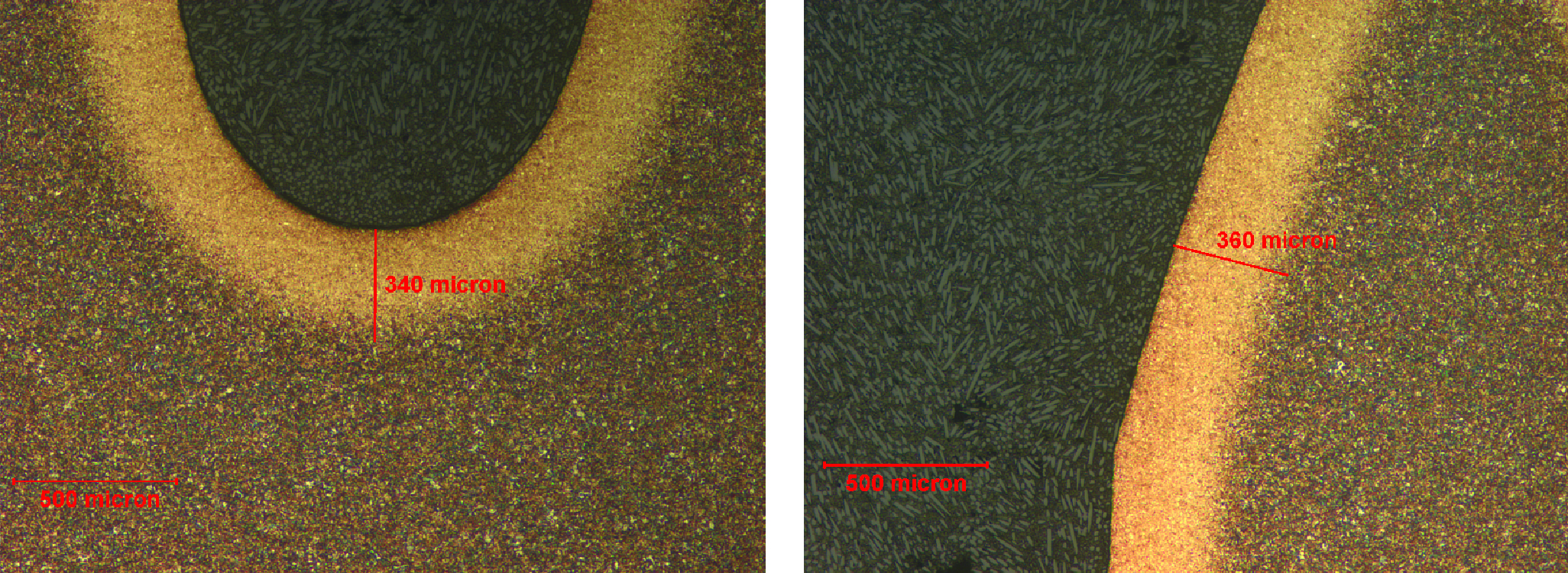
Another advantage of LPC processing over conventional carburizing is the depth of case attainable in gear tooth roots. The pitch to root ratio of the effective case depth after LPC is remarkably uniform. Oftentimes in conventional carburizing of gears, the case depth in the roots of teeth may only amount to half the case depth present at the mid-pitch tooth location. With LPC processing, the effective case depth present in the gear roots is nearly equivalent to the case depth present at the gear tooth midpitch location. This deeper case depth present in the gear tooth roots enhances fatigue life under tooth bending conditions and will outperform conventional carburized parts in this aspect.
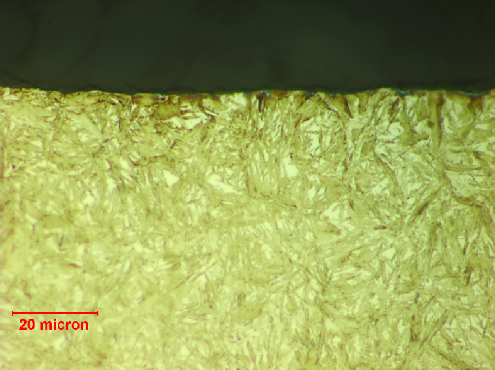
Another advantage of LPC is the absence of any inter-granular oxidation (IGO) on the surface of the part. This saves the gear manufacturer from grinding off the case to remove the IGO and saves valuable time and manufacturing costs. Typically .0003” to .0007” deep IGO will be present on any gears carburized in conventional endothermic atmosphere furnaces.
The LPC process produces excellent metallurgical and dimensional results which are required for high performance transmission gears. There are many types of gears and products well-suited for the LPC process and the advantages of this process have been outlined above. The main disadvantages of this process are that LPC equipment is capital intensive and the consumables are expensive. Process engineering, operation, and maintenance require higher skill levels than traditional carburizing. There is also a limitation of load sizes that can be processed as the gas quenching requires that lighter loads be processed in order to cool them rapidly enough.
Gas Nitriding
The gas nitriding process for case hardening of alloy steels allows complex configurations to be treated with minimal distortion. This process is performed at low subcritical temperatures and completely avoids the problems of structural transformations associated with high temperature austenitizing and quenching of steel during carburizing. Earlier in this article we detailed the three causes for distortion in carburizing which included stress relieving of pre-existing residual stresses, high temperature creep distortion, and phase transformations upon quenching. Since there are no phase transformations at low nitriding temperatures, there is no distortion from phase changes. There is little concern for distortion due to high temperature creep at the low subcritical nitriding temperatures. That leaves only stress relief of residual stresses as a possible cause of distortion during nitriding. In order to eliminate this source of distortion a typical manufacturing sequence for nitrided gears would be to rough machine, stress relieve at 50 ºF above the nitriding temperature, final machine putting as little stress into the parts as possible, and then nitride. Nitriding is often performed on finish-machined components with little distortion and usually requires no post-heat treatment machining to clean up the tolerances. The nitriding process basically consists of placing steel surfaces at nitriding temperatures in contact with ammonia gas (NH3). The ammonia dissociates at the steel surface providing atomic nitrogen which can then diffuse into the gear, react with specific alloying elements in the steel, and form alloy nitrides which creates a hardened wear resistant case below the gear’s surface.
There are many benefits of the gas nitriding process. Its purpose is to produce a very hard, wear resistant, load bearing case in relatively inexpensive alloy steels. The low treatment temperatures keep distortion and growth to a minimum and it is typically performed on finish-machined parts. This process is very simple to run and has fewer variables to control than the other case hardening processes discussed earlier. The lack of quenching which is a major source of variation in carburizing results is not present in nitriding and allows for better control and greater repeatability. The nitrided case also is not softened or tempered like carburized gears, which start to lose hardness at temperatures as low as 300ºF. Nitrided cases will not soften until exposed to temperatures above 1000ºF and can withstand high service temperatures. Isolated surfaces can be masked from nitriding and left soft for ease of machining, welding, or other purposes. The corrosion resistance of some low alloy steels is also slightly improved by nitriding.
Some limitations of gas nitriding include only being able to achieve shallow case depths (0.030” max for some materials) due to the low diffusion temperatures. The nitriding alloy selections are limited to materials that contain Cr, Mo, V, Ti, W, and Al alone or in combination. There are occasional problems with spalling of the case if nitriding networks form, but this can be minimized with proper controls. Nitrided stainless steels lose much of their corrosion resistance by nitriding as chromium becomes bonded to nitrogen, which breaks down the protective chromium oxide layer normally present on stainless surfaces. The gas nitriding process is a readily available heat treatment process that creates an extremely hard, load bearing wear resistant surface with depths ranging from .005” to .025” depth. It can be performed on many commonly available alloy steels with minimal size change and high retention of core mechanical properties.
Induction Hardening Gear Teeth
Induction heat treating is localized heat treatment used to increase the fatigue life, strength, and wear resistance of a component. Induction hardening is accomplished by placing the part inside an alternating magnetic field causing an electrical current to form at the surface. Heat is generated as a result of the I2R losses in the material and allows heat treaters to selectively austenitize only the surface material of a component while leaving the core material untransformed. Not only is the surface only selectively heated, but induction allows only those desired surfaces to be heated while other surfaces may be left cold. In the case of gears it is possible to only austenitize the near surface of a single tooth leaving the balance of the part cold during processing. The heated gear surface is subsequently quenched in either water, oil, or a polymer based quench to transform the austenite into martensite thereby increasing hardness in the required area while leaving the remainder of the component virtually undisturbed.
Gear Hardening:
There are numerous factors that determine the appropriate induction hardening process to choose. Items such as geometry, permeability of the material, and desired mechanical properties will dictate processing variables such as frequency, power density, and heat time.
There are many frequency selections to choose from when hardening gears. The relationship between frequency and current penetration depth are inversely proportional. Such that lower frequencies cause the current to form at deeper depths while higher frequencies generate heat immediately adjacent to the surface. Tooth form is a significant factor when selecting the correct frequency, as high frequencies will heat the tooth tips first and low frequencies will heat the roots first.
Power density and heat time are crucial to achieving the desired mechanical properties with the least amount of dimensional movement and associated risk of cracking. When calculating power densities a target value of 12 KW/in2 should be used to minimize total heat penetration into the component core. Heat time should always be optimized to achieve full transformation to austenite at the desired hardening depth.
Profile Induction Hardening:
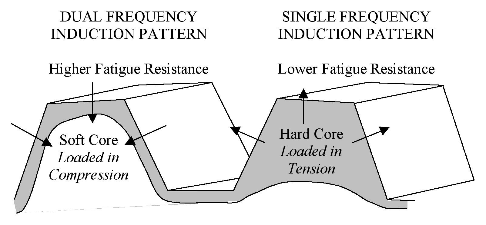
Profile induction hardening produces a tough core with associated tensile stresses and a hardened surface layer that exhibits compressive stress in the tips, flanks, and roots. Extensive product validation testing has determined that this combination of stresses best extend the component’s fatigue life and wear resistance over other types of induction hardening while also producing the least amount of dimensional movement.
The most common method of obtaining a profile hardening pattern is to use a “blend” of frequencies to actually heat the tips, flanks, and roots concurrently. This is accomplished by simultaneously generating high and low frequencies and passing them through the inductor at the same time. This type of power supply is relatively new to the market and is referred to as a “simultaneous dual frequency” generator. Most of these units allow the technician to individually adjust the intensity of the various frequencies seen by the part. This provides them the flexibility to customize or sculpt the shape of the pattern to the specific geometry of the tooth.
Single Tooth Hardening:
Single tooth hardening is primarily used to induction heat treat gear teeth to improve strength and wear characteristics. The process is accomplished by hardening one tooth root at a time. After each root has been hardened the system indexes the part to the next position and the process begins again. This process is time consuming as a 55 tooth gear will take 55 hardening cycles to complete. However, it is primarily used to harden very large, low volume parts that could not be done using conventional equipment due to the massive power requirements associated with heating the entire part at the same time or very large diameter gears that will not fit inside any existing carburizing furnaces.
To harden a tooth root the coil rests in between to adjacent teeth. This configuration hardens the tooth root and the flank of each adjacent tooth as shown in Figure 8. This method of hardening provides strength and wear resistance on the contact areas of the gear while minimizing dimensional movement by leaving the tooth tips unhardened.
Conclusion
A variety of heat treatment techniques exist for case hardening gears. Heat treatment processes can be tailored to maximize the life and optimize the performance of a gear in its service application by tailoring the heat treatment to produce specific desired properties. Distortion is always a factor in heat treatment processes, but it can be controlled and minimized by selecting specific processing parameters, being knowledgeable about fixturing, using different types of case hardening processes, and taking extra steps to ensure the gears have minimal stresses present in them prior to heat treatment that could be relieved. No one heat treat process is superior to the other, but ultimately they all compliment each other. Having an understanding of the processes available will help you choose which process is appropriate for your gear.


