


Induction hardening lends itself very well to heat treating steel shafts that will be loaded in torsion and/or bending. In both cases, it puts the strength at the surface where it is needed the most. It is a relatively quick and efficient process that allows the use of plain carbon steel and water quenching. Cracking after hardening is something that can occur depending on the part geometry and the grade of steel. Typically, it will occur at the surface at a stress concentration such as radius or groove. It may occur immediately after quenching or a short time later. Sorting can readily be done by magnetic particle inspection (MPI) commonly known as Magnafluxing.
Induction hardened shafts can provide excellent torsional strength depending on the case depth, surface hardness, and core hardness [1]. Torsional fatigue life is also very high due to the residual compressive stress created by hardening the outer area at and below the surface known as the case. When the case is transformed to hard martensite, it expands relative to the core, creating compressive residual stress, which can run deep into the shaft. This is what provides the excellent fatigue life. For the compressive residual stress to develop at the surface, the core also must be in tension, which can be significant. When the case expands axially, the core will resist but must be capable of expanding as well. Sufficient core ductility or elongation is the key. Without it, the residual tensile stress in the core can lead to internal cracking.
 Internal Cracking
In the 1970s, it was not uncommon to occasionally see internal cracking on heavy duty truck axle shafts after induction hardening. This was at a time when steel quality was not what it is today with the use of ladle metallurgy and vacuum degassing. Longitudinal stringer type micro- and macro-inclusions were much more prevalent, and shafts would sometimes split in half longitudinally for the entire length. On machined surfaces, macro-inclusions would show up during Magnafluxing, making crack detection a little more challenging. Macro-inclusions were almost never seen in random samples cut for micro-inclusion analysis. Even if you knew exactly where they were from MPI, it was difficult to section near them and grind and polish into them. However, Magnafluxing is a good tool to identify and quantify them and is what is used for magnaflux quality steels.
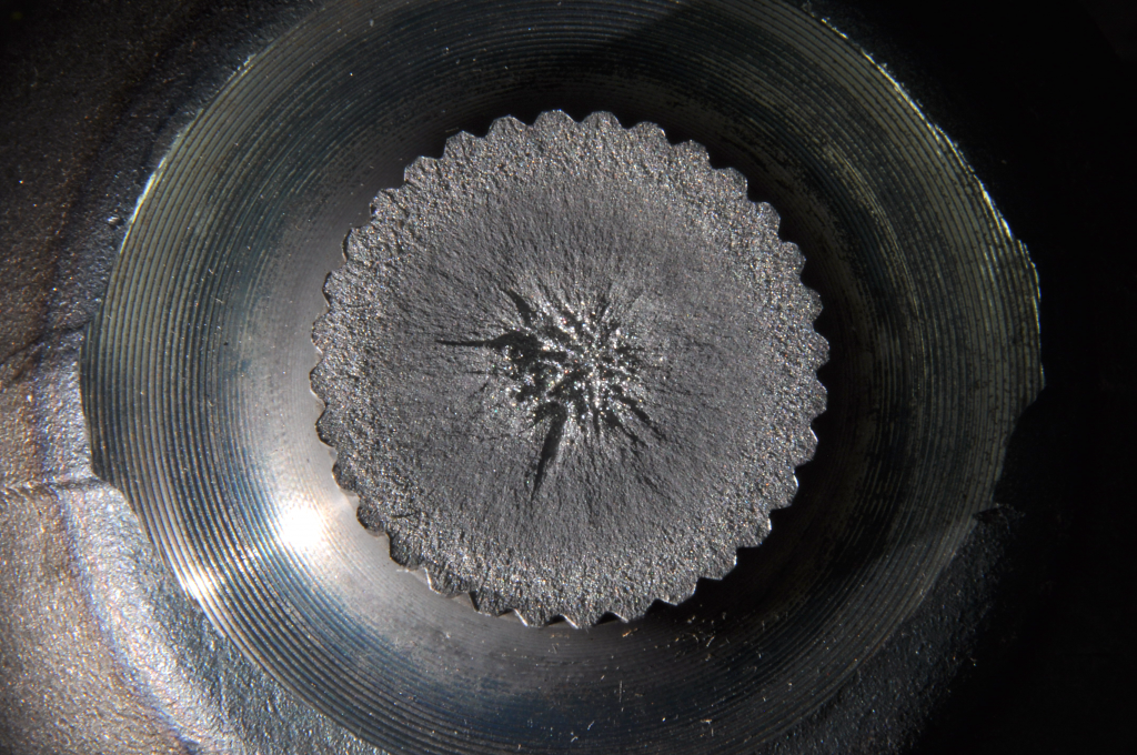
Today, steel quality is much better than it was in the 1970s, and it would be rare to see a longitudinal split on an induction-hardened shaft. However, induction-hardened shafts can and do also crack in the transverse direction. This occurs more often than is known. The maximum axial residual tensile stress occurs near both ends of the induction-hardening pattern near where the case depth begins to reduce [2]. This is where transverse internal cracks will occur as shown in Figure 1.
With the scanning induction-hardening process, the case depth is often deeper at the end where the scanning begins due to the dwell time necessary to begin the heating. It is tempting to believe the internal cracking is the result of the deeper case depth at this location; however, the cracking also occurs at the opposite end of the shaft where the case depth is not deeper [3].
Problems with transverse internal cracks
Transverse internal cracks have been known to occur for many years on induction-hardened shafts with no field concerns and no knowledge of their presence. It is only when something in the material or process changes and the cracks increase in size causing the shafts to fail before or shortly after being put into service that they become evident. This issue is more pronounced with deeper case depths because the residual stress profile is deeper.
The grade of steel also can have a significant effect on this type of cracking. Boron steels are much more prone to transverse internal cracking. This would include steel grades such as 15B41, 50B50, and 10B38. Small cracks that are less than 25 percent of the diameter typically do not cause any problems. Medium-size transverse internal cracks around 50 percent of the diameter may fail in service, and large transverse internal cracks that take up almost the entire diameter will typically fail prior to or during installation in the axle assembly or immediately after being put into service.
Transverse internal cracks were found on heavy truck axle shafts in the late 1970s. Initially they appeared to be intergranular to the naked eye. However, they were trans granular but appeared to be intergranular because the grain size was large and the individual grains were visible. Both ends of the 15B41 full float axle shaft were hot upset forged, and the grain size was larger in these areas, which decreased the ductility. The transverse internal cracks occurred at both ends because of the lower ductility of the steel, and this is where the longitudinal residual tensile stress was at a maximum. Transverse internal cracks were also discovered on 50B50 output shafts that were hot upset forged on one end only. The cracking could be heard on the shop floor as a “ping” or “tink” noise as the shafts cooled after tempering. This sound is an indication transverse internal cracking is occurring.
The transverse internal cracks were easily detectible by using pulse echo ultrasonic testing from the machined spline end. Approximately 20 percent of the shafts were cracking. The size of the cracks could be determined by how much sound got by the defect and was able to reach the end of the shaft. If the height of the defect peak was low and the majority of the sound reached the flange backwall, the defect was considered small. If the defect peak is larger and the backwall reflection is about the same size, the defect was medium. If none of the sound reached the backwall, the defect was large. When designing shafts, it is a good idea to have at least one end machined surface that can accommodate ultrasonic testing if necessary.
Increasing the core ductility
The fix or solution for this problem was to increase the core ductility by normalizing the shaft after forging and reducing the grain size in the hot upset forged ends. As forged, the grain size was up to ASTM 00. It is not the average grain size that is important, but instead the worst-case largest grain. Steel grain size varies widely in any given sample. Only a few very large grains can cause an internal crack problem. Keeping the worst case largest grain to ASTM 2 maximum kept the transverse internal cracks from occurring.
The transverse internal crack problem started due to a change in chemistry at the steel mill. The boron range is 0.0005-0.0030%, and the typical concentration was always about 0.0007-0.0010%. The mill decided to increase the boron concentration to the middle of the range around 0.0011-0.0016%. This is when the transverse internal cracks changed from small to large and the shafts began to fail at or prior to assembly. Normalizing was able to eliminate the transverse internal crack issue.
These axle shafts had been in production for many years prior to this problem occurring. Older shafts were obtained from the field and ultrasonically inspected. Small cracks were found at either or both ends of the shaft. However, no field failures were ever reported.
A few years later, similar 15B41 heavy truck axle shafts from a different manufacturer were ultrasonically inspected, and small transverse internal cracks were also discovered. Again, no field failures occurred. Normalizing was used to eliminate the problem.
A 1050M flanged semi float axle shaft
Another example on transverse internal cracking involved a 1050M flanged semi float axle shaft that had been in production for 20 years. A new design with a thicker flange was put into production, and transverse internal cracks began to appear. However, the rate of incidence was extremely low and only two cracks were found in two years of production. Both involved wheels separating from vehicles shortly after they were put into service. This low incidence rate makes it nearly impossible to run any trial to validate a solution. Again, normalization was employed.
Yet another example involved a 1040 flanged stub shaft with a cold-extruded shaft and a warm-formed flange that had cracks with small grains. The transverse internal crack occurred near the transition, and large grain size was not an issue here. Again, normalization was used to fix this issue as it increased the ductility or elongation.
Transverse internal cracking also occurred on a larger hot forged 1141 stub shaft. Normalization was put into place, but it didn’t fix the problem. Here, the grain flow did not follow the contour of the part. In the shaft portion, the grain flow buckled, leaving many small areas that were transverse to the shaft. This lowered the ductility in this area, causing the cracking. The solution was to modify the forging process and steel bar diameter.
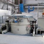
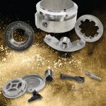
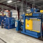
Medium carbon vanadium steel front yoke shafts had been in production for many years with no problems. The manganese content was increased to bring the hardness up from 229-260 BHN to 269-302 BHN. This caused a transverse internal cracking issue after induction hardening shown in Figures 2, 3, and 4 [4].
Hot forging process
In both cases, the grain size was large due to the hot forging process. This is a good example that shows increasing hardness or strength can cause transverse internal cracking rather than eliminate it. Quench and tempering were used to increase the ductility while still maintaining the higher hardness.
1038V hot forged semi float axle shafts experienced transverse internal cracking for many years; 100 percent manual ultrasonic testing was put into place. The rate of incidence was very low, only about 10 defective parts or less were found each year. In this case, the cracking was the result of abnormal grain flow. Eventually, defective parts got through the inspection process and failed in the field. Inspection is not the way to deal with this problem long term. A more permanent solution is needed. However, the low rate of incidence can make it very difficult to validate a solution because testing a few hundred parts may not provide any confidence.
Normalizing typically is and has been used to refine the grain size after hot forging. However, today that may not always work. Steel hot rolling schedules may include lower temperatures to better control grain size and mechanical properties of the hot rolled bar. As a result, normalizing can have the opposite effect and increase grain size due to the strain energy residing in the steel bar. This is similar to the abnormal grain growth that occurs in cold or warm formed forgings that are subsequently carburized. It is critical to make sure that normalization does not cause abnormal grain growth and create an internal cracking problem. A grain size test can be run on the steel bar using the normalization conditions.
Conclusion
To summarize, transverse internal cracking can and does occur on induction hardened shafts due to insufficient ductility or elongation in the core. This is normally the result of a large grain size or abnormal grain flow. The grade of steel also is important, and the rate of incidence can vary widely. Normalization or quench and tempering have been used to eliminate this issue.
References
- G. Fett, “Induction Case Depths for Torsional Applications,” 2009 ASM Heat Treating Conference.
- L. Ferguson, Z Li, V. Nemkov, R. Goldstein, J. Jackowski, G. Fett, “Modeling Stress and Distortion of Full-Float Axle Shaft During Induction Hardening Process,” Presented at 2013 HES Conference, Padua, Italy, May 2013, available at Fluxtrol.com.
- G Fett, “Induction Hardening Hot Forged Boron Steel Parts,” Metal Progress, May 1983, Page 52.
- ASM Metals Handbook, Volume 4C, “Induction Heating and Heat Treatment,” Pages 232-233.


 general practice for CQI-9 and AMS2750E")


