


falkThe aviation industry is changing toward more sustainable production, service, and maintenance of aircraft. Additionally, more and diverse aircraft are being developed, especially considering UAVs and VTOLs. This results in more diverse components. Additive manufacturing (AM) comes in handy to tackle those challenges. Due to the various parameters that influence the component’s properties, the qualification process is very complex.
No specific qualification is available among the existing AM part integrators. This article proposes a data-driven component evaluation process for the certification of aerostructures, considering all available data i.e., design, manufacturing and post-treatment data. Machine learning (ML) algorithms are used to predict the physical properties of components based on the data generated by monitoring their production. Necessary training data comprises non-destructive (NDT) and destructive tests (DT), whereas the quality assurance (QA) in a production environment works just with NDT data. Here a platform is presented that implements the processes necessary to guide a user through the certification process of an AM component made of AlSi10Mg, produced using laser powder bed fusion (LPBF).
1 Introduction and motivation
Additive manufacturing (AM) of metallic components offers great potential for use in aerostructures. The high requirements of the regulatory authorities for the certification of aircraft components and the necessary light-weight construction require a precise understanding of the structural behavior.
The high degree of flexibility of AM due to the moldless manufacturing process allows better light-weight designs. Combined with the demand for small quantities in aviation makes AM suitable for non-critical and low-critical parts. However, various types of defects occur during the AM process of metallic components, which influence the condition of the components and thus their structural properties [1, 2]. Controlling the occurrence of defects or predicting the structural behavior based on defects is complicated and involves a large effort [3,4,5,6].
Nevertheless, several applications of metallic AM components for aircraft already exist. Airbus designed a cabin bracket [7] that is used in the A350. Further examples for brackets are given in references [8, 9] and [10]. Heat exchangers are designed by Boeing [11] as well as by HiETA [12] or UTC’s Pratt & Whitney and Collins Aerospace [13]. Airbus designed a door locking shaft [14, 15] and Boeing, in cooperation with Spirit AeroSystems, a door lash [16]. Further applications are a hydraulic unit designed by Liebherr Aerospace [17], a lattice structured seat mount [18] or a NACA inlet designed by General Atomics [19]. Regarding engine components, Airbus designed a pylon [20], Vectorflow, a probe for measurements of temperature and air speed [21], and MTU Aero Engines, a borescope boss [22]. With special attention regarding laser powder bed fusion (LPBF) combined with AlSi10Mg material, Sogeti designed a cable mount [23] and Cobra Aero, an air-cooled piston engine for UAVs [24]. Those examples illustrate that AM has already found a place in some niche applications for aircraft components.
The certification process for AM components is currently similar to the process for conventionally manufactured components [25, 26]. On the other hand, AM production phases are not compatible with classic aviation certification documents derived from traditional manufacturing [27, 28]. According to Blakey Milner et al., it is necessary either to accommodate those existing certification documents or engage with emerging documents for AM structures [29].
During AM, data is collected using in situ process monitoring (ISPM) and subsequent tests, which can be included in the certification process. Based on this data, the component’s physical properties can be predicted. Holfeld et al. [30] demonstrated the implementation of the prediction through machine learning algorithms (ML). Although the application of ML for quality assurance of manufacturing processes is still a highly researched area, it is providing added value in some fields already [31, 32]. With the growing availability of process data, it will be possible to use ML to improve the quality assurance of AM [33]. These procedures open up new possibilities regarding the certification process for aerostructures [34].
2 Current certification of AM aviation components
2.1 Applicable regulations and standards
Current certification activities in the aviation industry are verified and approved by certification authorities that define the currently applicable certification specifications (CS). The CS contain technical requirements for the aircraft design. For each design aspect, paragraphs within the CS provide detailed information on how airworthiness is to be demonstrated. EASA defines them as acceptable means of compliance (AMC), which are regarded as soft-law [35].
AMCs can also be stated by the application of a referenced standard that is admitted by the certification authority. Standards developing organizations (SDOs), which define publicly available specifications for materials, processes and parts according to ref. [25] are for example:
- SAE-AMS Additive Manufacturing Committee.
- ASTM International Committee F42.
- ISO Technical Committee 261.
This article relates primarily to the application of European aviation law and thus the EASA’s CS are applicable. In general, AM components must meet the same certification specifications as conventionally manufactured components. A distinction is made indirectly by classifying additive manufacturing as a new fabrication method. Each new fabrication method must be qualified through test programs that identify the uncertainties resulting from the fabrication method and determine the critical process variables that must be met during fabrication process [36].
The 2020 publication by the Aerospace Industries Association (AIA), “Recommended Guidance for Certification of AM Components,” dives deeper into the certification process of such new fabrication method as one of the most comprehensive frameworks to date for AM components in aviation applications [37]. This widely referenced document systematically examines every stage of the certification process, from raw feedstock powder over cured bulk material to the finished component. For each step, it outlines how quality assurance standards are established and how they can be maintained in future serial production. With this approach, the document focuses on the compliance finding for the following three paragraphs from the CS-25, the applicable CS for large airplanes:
- § 25.603 Materials.
- § 25.605 Fabrication Methods.
- § 25.613 Material strength properties and Material Design Values.
Starting with the raw feedstock material, it is essential to ensure the material properties relevant to the component’s application are achievable using the chosen powder. Achieving optimal properties in the final material requires close alignment between the raw material and the manufacturing process. This alignment is referred to as process development, where the goal is to determine the ideal process conditions, documented as key process variables (KPVs), and the associated tolerance bands whose compliance ensures a stable process. For several process types, there are different ready-to-use specifications available that assist in identifying these KPVs such as the SAE AMS7003 for the LPBF process [38]. According to Russell et al. [25], the most influential factors on part quality are listed as follows:
- Feedstock attributes (purity, powder particle shape and size distribution, chemistry).
- Processing conditions and controls (laser or electron beam power, hatch width, scan rate).
- Thermal conditions during build (layer thickness, platform pre-heating).
- Build atmosphere and purity (shield gas or high vacuum).
- Post-processing (Hot Isostatic Pressing (HIP), heat treatment, and machining).
- Finished part properties (microstructure, discontinuities, roughness, non-destructive, and destructive test methods).
- Equipment (machine-to-machine variation, calibration, maintenance).
- Personnel (training, certification).
- Facilities (certification).
In addition to the KPVs, the cured material also shows important key characteristics (KCs), such as density and surface roughness, which provide important information about the cured material and process quality. In general, a certification project focuses on finding significant KPVs and KCs while the quality assurance (QA) process involves monitoring the identified KPVs and KCs to enable early intervention if these parameters deviate from defined limit values. [37]
A central element of the certification framework is the establishment of material allowables, which quantify the lower limit of the material properties of the cured bulk material at a stable manufacturing process. The MMPDS handbook delivers analysis techniques to determine material allowables [25, 39]. To address part-specific features, scale factors are introduced, resulting in the so-called design values (See Figure 1)

Material allowables and design values represent statistically verified material properties that are needed to design a component since the actual material properties are manufacturing process-dependent and have a scattering. Especially, when considering the AM process. The final part must be designed based on the material allowables and design values (Figure 2). In the final step, tests at component-level are carried out to validate the final part design.
During the certification process of a component, the boundary conditions for a stable manufacturing process are determined and the requirements for a reliable quality assurance chain for serial production are documented.

2.2 Exemplary QA chain
The QA in AM throughout the process can be structured in three steps [40]:
- Preprocess: Machine acceptance tests, system maintenance, material quality control, process parameter validation.
- In-process: System monitoring and in-situ process monitoring of the process.
- Postprocess: Non-destructive and destructive testing methods.
To guarantee sufficient part quality, manufacturers monitor process data that has the most influence on part quality. The manufacturing process comprises the following steps as used by part integrators like GE Aerospace, MTU Aero Engines and Airbus Helicopters:
- 1 Raw material supply: To ensure appropriate feedstock attributes, suppliers must qualify powder quality i.e., density, size distribution and morphology [41, 42] as required by ref. [15, 25].
- 2 Print: Monitoring of print data, which comprises laser parameters, hatch strategy, recoat parameters and build chamber parameters [25].
- 3 ISPM: Online monitoring approaches allow systematic deviation detection [43]. One of these methods is optical tomography as applied by refs. [41, 44].
- 4 Calibration and maintenance: Part integrators monitor preventive maintenance, pre-build calibration, and factory environment controls [25].
- 5 Clean: Removal of lose powder.
- 6 Post-Treatment: Part integrators monitor the post processing parameters, such as mechanical finishing and thermal exposure [25]. Usually hot isostatic pressing (HIP) is therefore applied [25, 45].
- 7 Inspection: According to Russell et al., the qualification of the final component may comprise non-destructive (NDT) and destructive testing (DT) of witness specimens [25]. NDT is conducted comprising the following methods:
CT is applied to detect inner defects such as porosity and lack of fusion [15, 43]. Dye penetrant, such as fluorescent penetrant inspection (FPI) is used to exclude surface defects [15, 43]. 3D scanning is applied to validate the part’s geometrical compliance [15]. DT methods inspect parts with cutups and specimens for the assessment of grain size, porosity, and surface finish as well as on-going material testing [25]. These tests represent a cross-check of all other validation methods performed and ensure the overall mechanical performance of the AM application i.e., the component.
8 Part release: After determination of the quality, the part is released.
In the current certification, approaches for component monitored parameters and settings are compared against tolerance bands determined in preliminary tests for a stable manufacturing process. This is used as the basis for showing compliance with the requirements for the manufactured components [37, 46].

3 Concept for a new data-based QA of aircraft AM components
The aim of the data-based QA process is to draw an appropriate conclusion about a component’s quality (Figure 3). To do so, data available during the entire manufacturing process must be analyzed as all data are considered to potentially influence the quality. Data will be generated and collected during the preparation of the print (e.g., powder analysis), the manufacturing process itself (e.g., ISPM), the post-treatment (e.g., surface finish), and the inspection (e.g., roughness measurement) of the component.
In the data-based approach, material allowables and design values are still used as in the conventional approach, but the approach picks up at the point where the quality of the component is assessed.

Figure 4 illustrates the comparison of both procedures to evaluate the component’s properties as it is done in the conventional case and proposed in the data-based approach. The currently known relevant KPVs for the present manufacturing process are taken from SAE’s AMS7003A [46].
For the conventional case, every single monitored KPV and KC needs to be checked for compliance to assure the component properties meet at least the requirements. For the data-based case, there will be a process data module driven by ML that accepts all preparation, monitoring and non-destructive inspection data as input and generates specific, reliably predicted resulting material properties for each individual component. This holistic evaluation of all data for a component has an enormous advantage that a component is only considered scrap if all KPVs and KCs combined show the resulting material properties do not meet the requirements. This is possible because the process data module can recognize interdependencies between different parameters.
Figure 4 clearly shows the decision whether the component meets the requirements is less complex for the deciding person and more precise in the data-based case since there are less parameters to be checked for compliance and the output is a specific value instead of a range.
To develop the data-based approach, the data from KPVs, KCs and destructive tests is used to train the ML models behind the process data module. Evaluations of ISPM data, which is not considered in the conventional case but provides valuable information about the component quality after evaluation, are also included here [47, 48].
By incorporating all available data of the entire process, the process data module can recognize and react to altered conditions in the manufacturing process, provided these conditions do not exceed the boundaries of the ML’s training data. There is no need to qualify a completely new process due to changing circumstances, as it is currently defined in process specifications [37, 46].

4 Implementation of the data-based QA approach
The goal of the process data module is to evaluate the influences of all provided data and learn their impact on the physically measurable properties, so a statement about the structural properties of a component can be made without having to destroy the component.
It takes the following five steps to implement the data-based approach:
4.1 Data preparation
All relevant process parameters, measurable influences such as ISPM data (e.g., build chamber temperature, oxygen content), destructive, and non-destructive component information are harmonized and provided as input to the ML algorithms. The results of the destructive tests are the target values to be predicted based on the remaining information.
Through a prior evaluation of in situ online tomography data, defects in the component can be identified already during the manufacturing process. This can partly replace time-consuming CT scans. If anomalies that cannot be detected by online tomography need to be considered, CT scans of critical component areas can be performed.

4.2 ML model selection
The process data module consists of trained convolutional neural networks (CNNs) that take multidimensional input data and predict the corresponding material properties. CNNs have been shown to have a high potential to find component defining properties within production data [49].
It should be noted the process data module consists of separately trained ML models for each respective parameter to be predicted.
4.3 Training of the ML models
A training data set consists of all available data from a destructive test (e.g., a static tensile test, see right side of Figure 5) as well as all available inspection and monitoring data (see left side of Figure 5). For each individual specimen, the required input data and the result of the destructive test must be provided. From all available training data sets, about 85 percent are used for the training of the model [50].
For a reliable prediction of structural properties based on this data, the training data must contain anomalies that can be detected through ISPM and influence the properties determined by structural tests. Additionally, sensitivity analyses are carried out during the training of the models. This identifies inspections and monitoring procedures (left side of Figure 5) that do not provide any information about the quality of the component in the holistic view and can therefore be omitted. After the training, every trained model can predict a characteristic value from the right-hand side using only the data shown on the left-hand side of Figure 5.

4.4 Verification of the ML models
A verification of the module is necessary to prove that it works as expected. Complete data sets including destructive tests are required for verification, too. It is important that these data sets differ from those used for training to verify that from unknown input data can be predicted correctly. Therefore, roughly 15 percent of the available training data sets are used to verify the training of the model [50].
By considering the distribution of the results from the destructive tests, the predictions of the trained model can be put into context. Statistical metrics, such as standard deviation and confidence intervals, allow for an assessment of accuracy, which in conjunction with the actual results enables the evaluation of each component. The verification must ensure the results of the process data module are comprehensible and reproducible [34].
As a result of the verification of the models, the accuracy of the prediction of the characteristic value can be measured by the deviation of the predicted value from the destructively measured value.
4.5 Application of the ML models
To use the trained and verified ML models representing the process data module, only the process monitoring and non-destructive testing data specified on the left-hand side of Fig. 6 is required. As a result, every model provides separate characteristic values for each individual component. The resulting material properties are obtained after applying the deviation for the respective model to the predicted values. These properties are representative of the quality of the specific manufactured component (Figure 6)
Since trained and verified models are used, the prediction duration of the component’s properties relies solely on the provisioning time of the input data.
5 Implementation of a data-based certification platform
5.1 Platform development
An essential part of certification projects and quality assurance processes is the documentation in accordance with regulatory authorities (e.g., EASA and FAA) requirements for obtaining part design and manufacturing approval. As the tasks in such projects are carried out by different parties, collection, management and evaluation of all associated data at different locations represent a major challenge. To solve this challenge, a central certification platform is introduced that can be considered a project management tool for certification projects and for setting up quality assurance processes for AM components in the aviation industry. On this platform, all relevant certification steps are implemented, and project documentation is supported by input forms to automatically create certification-relevant and approvable documents. The platform guides through six main steps:
- 1 Project Initiation: Definition of general project data, such as the project goal, part description, milestone plan, and certification team. In this section, responsibilities can be distributed and signing authorizations delegated between different project stakeholders.
- 2 Conceptual Design: The demonstration of primary component specifications via part sketches, definition of manufacturing process and material as well as choosing the valid certification specification and declaration of the part criticality acc. to CM-S-008 Issue 4 [51] is carried out.
- 3 Part Design Development and Compliance Planning: The creation of the compliance checklist matrix describing the verification procedure via means of compliance from the certification specification takes place. Also, the test program is defined, which is required for additive manufacturing and described in Section 3. For both the conventional and the data-based approach, this extensive test program is documented in a detailed certification plan.
- 4 Compliance: Compliance is shown via executing the certification plan and meeting the requirements for all means of compliance. It’s shown stepwise by first determining material allowables, afterward the design values and then showing compliance for the final part. For the conventional quality assurance process, this section is also used to determine the tolerance bands for all predefined KPVs and KCs.
For the data-driven approach, this section is used to train different ML modules and analyze the initial process parameters as sensitivity studies might be carried out with the trained model to check the relevance of the initially defined KPVs and KCs.
- 5 First Article Inspection (FAI): The part design is released, and the final manufacturing process is captured in the process control documents. At FAI, the part quality is observed via non-destructive tests. With higher part criticality, destructive tests at witness specimens are required.
- 6 Quality Assurance: With the approval of the first article and the associated manufacturing process, the certification project is finished, and the part is ready to be manufactured at the production organization approval (POA) holder. During serial production, the quality assurance process needs to be applied according to the process control documents. For both the conventional and the data-based approach, the platform acts as a process monitoring control center. In situ KPVs and ex situ KCs can automatically be transferred to the platform via interfaces. In the data-based scenario, the trained and verified process data module is used to evaluate the quality of the manufactured components.

5.2 Conceptual validation
For a conceptual validation of the platform, a demonstrator (Figure 7) was used to prove all steps. The weight-optimized demonstrator is intended to replace a conventionally manufactured bracket of a ventilation duct in large airplanes.
First, the applicable paragraphs of the certification specification CS-25 are compiled and the associated AMCs are defined.
The verification of the associated AMCs is done by analyzing the raw feedstock powder (§25.603), establishing a stable manufacturing process (§25.605) and manufacturing of standard and part-related test specimens to determine material allowables via tensile test specimens and fatigue specimens over multiple print jobs (§25.613).
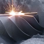
A typical print job is shown in Figure 8. The specimens are produced from AlSi10Mg using the parameters given in Table 1.

The tensile test specimens are designed according to DIN EN ISO 6892–1 and have a diameter of 5 mm and cylindrical form. The fatigue test specimens are designed according to DIN EN 6072 corresponding to type B with a reference cross section of 12.5 mm2. At the time of writing, 309 tensile test specimens and 515 fatigue test specimens were examined. They have been manufactured with batch size of 103 specimens. Surface treatment was conducted using barrel finishing. HIP was not applied to the specimens.
In addition to the AM process data, two monitoring systems were used: optical tomography [44] and powder bed monitoring.
Regarding non-destructive inspections, tactical roughness measurements according to DIN EN ISO 4287 were conducted. Density was measured using Archimedes’ method according to DIN EN ISO 3369. Moreover, all specimens were 3D scanned using an Atos Triple Scan 16 M. Selected specimens were CT-scanned as well. Regarding destructive testing, tensile tests according to DIN EN ISO 6892-1 were performed. Moreover, fatigue tests with an amplitude of 1200 N and a stress ratio R = –1 were conducted. Finally, hardness tests according to DIN EN 6072 were conducted as well. For further information about the data retrieval, see [2].
In sum, 108 different properties were considered during compliance data generation. As shown in the following Table 2, the properties can be categorized in different types.

Each property type brings different requirements for data acquisition and transmission to the platform. The logistical effort e.g., for density measurement is as follows:
After manufacturing specimens and parts, a test order for the density measurement is sent to a test laboratory via the certification platform. The laboratory executes the density measurement based on a specific measurement protocol, which is defined in the associated qualification test plan, to ensure comparability between different specimens. The test laboratory can upload the test protocol with the included density results to the platform. A certification engineer can then import the protocol into the analysis tool of the platform.
In terms of the conventional certification process, tolerance bands can be automatically extracted from the density data with lower and upper limits that need to be observed in serial production (Figure 9). In the case of the data-based quality assurance process, the density data needs to be imported into the process data module described in Section 4.
Certification engineers are assisted by statistical evaluation tools in finding correlations, trends and deviations during the manufacturing process. The assistive use of ML for data analysis can lead to a better understanding of interdependencies of different properties, reveal unnecessary KPVs/ KCs and thus reduce monitoring expenditure.
As the database of the process data module grows during serial production, destructive tests on witness specimens might become obsolete at a certain point even though the ML models need to be retrained when additional information becomes available. One of the biggest benefits in comparison to the conventional quality assurance process is the holistic consideration of all process data.

6 Conclusion and outlook
The platform guides users through the complex field of certifying AM components. It assists in generating the right documents as well as approving and depositing these in a central ecosystem. One major challenge is that QA in AM is associated with increased process monitoring and testing, which generates large amounts of data. To collect, bundle and understand this data, a centralized and digitalized management system is required. The certification platform addresses this challenge. The present transformation from the conventional isolated single parameter-based to a holistic data-based certification and QA process results in a deeper understanding of process specific interdependencies. Monitoring, inspections, or post-treatments not expected to have a relevant influence on the resulting material properties can be identified by means of sensitivity analysis. Additionally, the users can benefit from the substitution of time and cost-intensive ex situ measurement procedures (optical tomography replaces CT scans) and a reduction of wrongly declared scrap.
In future, further improvements in QA can be achieved by data-based validation. Based on trained process data modules, it is theoretically possible to optimize the adjustable variables of the AM process and post-treatment processes by interpreting the models backwards.
Provided the ML models can work with input data with variable dimensions and make statements about the component quality even before the end of the QA chain, further use cases are conceivable. For example, the known correlations of all variables in the process could be used to generate suggestions for application-oriented post-treatment of individual components. It is also possible to deliberately skip individual process steps during post-treatment if the component quality is already sufficient for the planned use case.
The high effort required to generate data purely through physical tests and inspections limits the amount of data that can be generated. In future, methods could be used to synthetically enlarge the database, e.g., through validated structural simulation tools [30].
As the size of the database increases over time, it may also be possible in the future to create compliance statements based on similarity for an entire component by demonstrating similarity with already certified components, processes, and materials. This could either lead to a significant reduction in the testing program or even to a test-free certification.
References
- Zhang B, Li Y, Bai Q (2017) Defect formation mechanisms in selective laser melting: a review. Chin J Mech Eng 30:515–527.
- Rümmler C, Neumann GRH, Groh W, Hähnel F, Grumbt G, Tropschuh R, Schiemann T, Markmiller JFC (2024) Study of the influence of additive manufacturing applicable surface treatment methods on mechanical part properties for use in aerospace applications. CEAS Aeronaut J 1:481–495.
- Marola S, Bosia S, Veltro A, Fiore G, Manfredi D, Lombardi M, Amato G, Baricco M, Battezzati L (2021) Residual stresses in additively manufactured AlSi10Mg: Raman spectroscopy and X-ray diffraction analysis. Mater Des 202:109550.
- Limbasiya N, Jain A, Soni H, Wankhede V, Krolczyk G, Sahlot P (2022) A comprehensive review on the effect of process parameters and post-process treatments on microstructure and mechanical properties of selective laser melting of AlSi10Mg. J Market Res 21:1141–1176.
- Finfrock CB, Exil A, Carroll JD, Deibler L (2018) Effect of hot isostatic pressing and powder feedstock on porosity, microstructure, and mechanical properties of selective laser melted AlSi10Mg. Metallogr Microstr Anal 7:443–456.
- Bernevig-Sava MA, Stamate C, Lohan N-M, Baciu AM, Postolache I, Baciu C, Baciu E-R (2019) Considerations on the surface roughness of SLM processed metal parts and the effects of subsequent sandblasting. IOP Conf Series Mater Sci Eng 572:012071.
- Langnau L (2015) Additive manufacturing enables “bionic” aircraft designs, https://www.engineering.com/additive-manufacturing-enables-bionic-aircraft-designs/. Accessed 4 December 2024.
- GKN Aerospace: Additive Manufacturing at a Tier 1 aerospace supplier, 2016. https://www.metal-am.com/articles/gkn-aerospace-3d-printing-at-a-tier-1-aerospace-supplier/. Accessed 4 Dec 2024.
- Topology optimization and DMP combine to meet GE Aircraft engine bracket challenge, 2017. https://www.3dsystems.com/learning-center/case-studies/topology-optimization-and-dmp-combine-meet-ge-aircraft-engine-bracket. Accessed 4 Dec 2024.
- Liebherr-Aerospace Starts Serial Production of 3D Printed Components – Liebherr, 2019. https://www.liebherr.com/en-de/n/liebherr-aerospace-starts-serial-production-of-3d-printed-components-24984-3704916. Accessed 4 Dec 2024.
- Boeing (2022) IQ Innovation quaterly 2022 Q3 Volume 6, https://www.boeing.com/content/dam/boeing/boeingdotcom/features/innovation-quarterly/2022/Innovation_Quarterly_2022_Q3_080222a.pdf.
- “Exchanging metal 3D printing solutions with HiETA,” 2017. [Online]. Available: http://www.renishaw.com/sv/exchanging-metal-3d-printing-solutions-with-hieta-42436. Accessed 4 Dec 2024.
- Pioneering new possibilities for Additive Manufacturing in aerospace, 2019. https://www.metal-am.com/articles/pioneering-new-possibilities-for-3d-printing-in-aerospace/. Accessed 4 Dec 2024.
- 3D Printing in Aerospace | EOS, https://www.eos.info/industries/aviation. Accessed 4 Dec 2024.
- Wolf C, Neumann A, Reinspach S (2023) Development, industrialization and qualification of a lever-shaft-integration for a long range aircraft. In: Rieser J, Endress F, Horoschenkoff A, Höfer P, Dickhut T, Zimmermann M (eds) Proceedings of the Munich Symposium on Lightweight Design 2021. Springer Berlin Heidelberg, Berlin, Heidelberg, pp 154–159.
- What Is the Role for Additive Manufacturing in Aircraft Structural Components? 2024, https://www.additivemanufacturing.media/articles/what-is-the-role-for-additive-manufacturing-in-aircraft-structural-components. Accessed 4 Dec 2024.
- Liebherr (2018) First metal 3D-printed primary flight control hydraulic component, https://www.eos.info/industries/customer-success-stories/liebherr-3d-printed-primary-flight-control-hydraulic-component. Accessed 4 Dec 2024.
- Danon B (2017) How this light-weight airplane seat can save airlines $200,000,000 (and dramatically reduce carbon emissions), https://adsknews.autodesk.com/sv/stories/how-this-light-weight-airplane-seat-can-save-airlines-200000000-and-dramatically-reduce-carbon-emissions/. Accessed 4 Dec 2024.
- “At general atomics, do unmanned aerial systems reveal the future of aircraft manufacturing?” November 2024. https://www.additivemanufacturing.media/articles/at-general-atomics-do-unmanned-aerial-systems-reveal-the-future-of-aircraft-manufacturing. Accessed 4 Dec 2024.
- Jackson B (2017) Airbus installs first 3D printed titanium bracket on a production A350 aircraft, https://3dprintingindustry.com/news/airbus-installs-first-3d-printed-titanium-bracket-production-a350-aircraft-121212/. Accessed 4 Dec 2024.
- Durable up to the Sound Barrier and Beyond, 2018. https://www.eos.info/industries/customer-success-stories/vectoflow-flow-measurement-probe-aerospace. Accessed 4 Dec 2024.
- MTU (2018) An Intelligent Strategy for Achieving Excellence: MTU Relies on Additive Manufacturing for its Series Component Production. https://3d.eos.info/hubfs/Customer%20Success%20Stories/Metal/CS_M_Aerospace_MTUAeroEngines_en.pdf.
- Additive Manufacturing for the new A350 XWB, 2018. https://www.eos.info/industries/customer-success-stories/airbus-a350-xwb-3d-printed-cable-mount. Accessed 4 Dec 2024.
- Case study: Cobra Aero reduced air-cooled cylinder weight by 50% with nTop, 2023. https://www.ntop.com/resources/case-studies/cobra-aero-multiphysics-simulation-drone-engine/. Accessed 4 Dec 2024.
- Russell R, Wells D, Waller J, Poorganji B, Ott E, Nakagawa T, Sandoval H, Shamsaei N, Seifi M (2019) Qualification and certification of metal additive manufactured hardware for aerospace applications. Additive manufacturing for the aerospace industry. Elsevier, pp 33–66.
- EASA (2021) Final Certification Memorandum ref. CM-S-008 Issue 3 on Additive Manufacturing.
- Uriondo A, Esperon-Miguez M, Perinpanayagam S (2015) The present and future of additive manufacturing in the aerospace sector: a review of important aspects. Proc Inst Mech Eng, Part G J Aerosp Eng 229:2132–2147.
- S. Singamneni, Y. Lv, A. Hewitt, R. Chalk, W. Thomas und D. Jordison, “Additive Manufacturing for the Aircraft Industry: A Review,” Journal of Aeronautics & Aerospace Engineering, Bd. 08, 2019..
- Blakey-Milner B, Gradl P, Snedden G, Brooks M, Pitot J, Lopez E, Leary M, Berto F, Du Plessis A (2021) Metal additive manufacturing in aerospace: a review. Mater Des 209:110008.
- Holfeld D, Theurich F, Rauschert A, Neumann G, Hähnel F, Markmiller J (2024) An application of ai for online estimation of the impact of imperfections in additive manufactured components. In: First working conference on artificial intelligence development for a resilient and sustainable tomorrow, Springer Fachmedien Wiesbaden, p 153–163.
- Elongovan M (2015) Machine learning approach to the prediction of surface roughness using statistical features of vibration signal acquired in turning. Procedia Comput Sci, pp 282–288.
- Hariharan V, Sivaraman K (2024) Machine learning techniques for quality control in textile fabric manufacturing. In: International conference on sustainable computing and smart systems (ICSCSS), pp 902–907.
- Mondal S, Goswami S (2024) Machine learning techniques for quality, Int J AI Mater Des, pp 21–40.
- EASA (2024) EASA Concept Paper: guidance for Level 1 & 2 machine learning applications.
- Hinsch M (2019) Industrial aviation management: a primer in European design, production and maintenance organizations, Springer Berlin Heidelberg.
- EASA (2020) Certification specifications and acceptable means of compliance for large airplanes (CS-25).
- AIA Additive Manufacturing Working Group (2020) Recommended guidance for certification of AM component.
- SAE International (2018) AMS7003: Laser powder bed fusion process.
- BM Institute (2024) MMPDS-2024: Metallic materials properties development and standardization, Battelle Memorial Institute.
- Minet K, Saharan A, Loesser A, Raitanen N (2019) Superalloys, powders, process monitoring in additive manufacturing. Additive Manufacturing for the Aerospace Industry. Elsevier, pp 163–185.
- Carl V (2015) Monitoring system for the quality assessment in additive manufacturing, Boise.
- Saracyakupoglu T (2022) Certification steps for the additively manufactured aviation-grade parts. Eur J Res Dev 2:33–42.
- Rott S, von Lautz J (2023) A proposal for cost effective quality assurance. In: Joint EASA-FAA Additive Manufacturing Workshop 2023, Köln.
- EOS (2019) Optical tomography enables considerable savings in quality assurance, https://uk.eos.info/04_consulting_service_software/software/pdf_software/cs_m_aerospace_mtu_en_web.pdf. Accessed 3 December 2024.
- Uhlmann E, Kersting R, Klein TB, Cruz MF, Borille AV (2015) Additive manufacturing of titanium alloy for aircraft components. Procedia CIRP 35:55–60.
- SAE International (2022) AMS7003A: laser powder bed fusion process.
- Rott S (2022) Homogenisierung lokaler Prozesscharakteristika für das Laserstrahlschmelzen, 1, Auflage. Apprimus Verlag, Aachen.
- Ero O, Taherkhani K, Toyserkani E (2023) Optical tomography and machine learning for in-situ defects detection in laser powder bed fusion: a self-organizing map and U-Net based approach. Addit Manuf 78:103894.
- Ani OI (2024) Advanced manufacturing with machine learning: enhancing predictive maintenance, quality control, and process optimization, Al-Rafidain J Eng Sci.
- Kohavi R (1995) A study of cross-validation and bootstrap. In: International joint conferences on artificial intelligence.
- EASA (2024) Proposed update to issue 4 of Certification Memorandum ref. CM-S-008 on additive manufacturing.


 general practice for CQI-9 and AMS2750E")


