Today, powertrain development is driven in the direction of weight reduction by replacing heavier components with low-cost or higher strength alloys for industries such as automotive, aerospace, and process engineering. Accurate prediction and optimization of the heat treatment process of metal parts is important to achieve optimum material properties or to increase the magnitude of surface compressive residual stress from local thermal gradients and solid phase transformation timing during hardening processes, thereby extending component life during operation. Among all other heat treatment techniques, the immersion quenching process has long been identified as one of the most important methods to fulfill the aforementioned requirements. In order to achieve the desirable microstructure and mechanical properties of the metal piece, steel components are heated to an austenitization temperature, followed by immediate submerging into quenching media [1]. The common austenitization and soaking temperature of steel gears is approximately above 900°C. The temperature varies based on the steel grade. During quenching hardening of steel components, the latent heat released during solid phase transformations affects the cooling significantly, which needs to be considered in heat treatment process modeling.
The paper features the results of the Eulerian multi-fluid model implemented within the commercial CFD code AVL Fire coupled with DANTE®, using the Abaqus/Standard finite element solver. The coupled modeling is capable of considering the solid phase transformation kinetics, which affects the microstructure, thermal, and mechanical properties. Phase transformation during quench hardening also involves releasing latent heat, which is considered in this study.
In this paper, a test gear component made of Pyrowear® 53 is simulated, and the modeling results include the entire history of the part response during hardening including heating, carburization, and quenching. The temperature gradients predicted by the presented model reproduce the latent heat release during the phase transformation. It is clear that neglecting the additional heat source would result in very different thermal gradients and consequently very different thermal stresses and surface properties of the treated component.
Theoretical Background and Simulation Setup
The Eulerian multi-fluid model considers each phase as interpenetrating continua coexisting in the flow domain, with interfacial transfer terms accounting for phase interactions where conservation laws apply [2]. The averaged continuity, momentum, energy, and boiling models equations are well-described in works of Srinivasan et al. [3] and Greif et al. [4]. The methodology is applied in an industrial environment as described by Jan et al. [5] and Mulayim Kaynar et al. [6].
The gear geometry is shown in Figure 1. The bore diameter of the gear is 48.35 mm, the tip diameter is 106.25 mm, and the total number of teeth is 41.
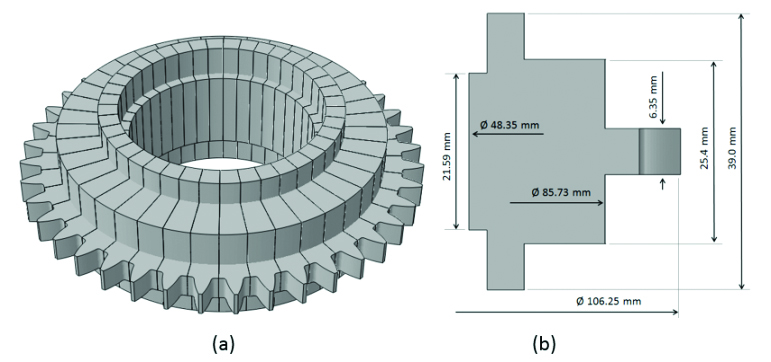
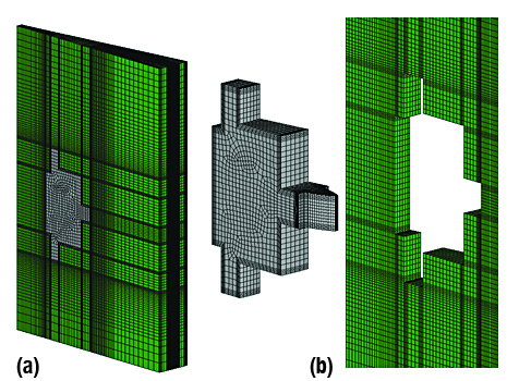
Figure 2 shows finite element meshing of the computational model. In this coupled model, the fluid and the solid structure are modeled by different computational codes, and their geometries are shown in Figure 2. It is assumed that all the gear teeth behave the same during quenching, so the gear is modeled using a single tooth with cyclic symmetry boundary conditions.
CFD Simulation Results and Discussion
The modeling results shown in Figure 3 are the volumetric fraction of oil to illustrate the boiling process and the temperature distribution of the solid gear at four different time snapshots during quenching. The results are shown on the planar cut through the fluid domain (top row) and on the surface of the structure. The gear temperature prior to quenching is 915°C.
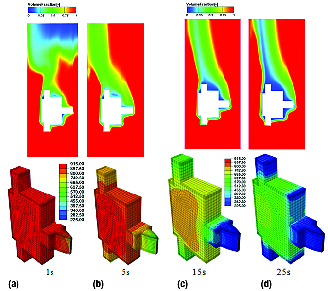
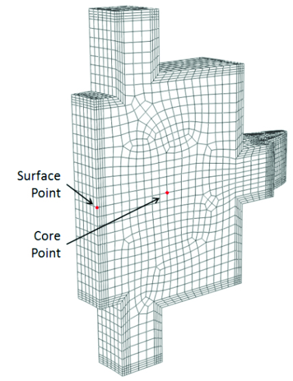
Figure 4 shows two points selected to study the cooling history of the gear during quenching. The surface point is located at the bore surface, and the core point is located at approximately the center of the cross-section.
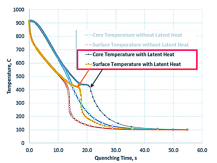
The thermal properties during quenching are affected by the temperature, as well as the phase transformations because different phases have different thermal properties. The overall thermal properties are calculated from the volume fractions of individual phases and their properties. The cooling history of the part is also significantly affected by the latent heat released due to phase transformation. By turning off the latent heat in the quenching model but still including the phase transformations, the effect of latent heat is shown in Figure 5. The bump in the time-temperature profile after 15-20 seconds represents the latent heat release. Slower cooling is clearly visible (yellow and gray profile), thus affecting the local cooling and overall temperature gradients. Orange and blue curves show the case without latent heat consideration.
Thermal and Stress Modeling Using DANTE
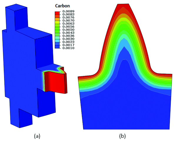
Prior to quench hardening, the gear tooth is gas carburized with all other surfaces being copper plated. After carburization, the gear is reheated for hardening. It is important to include the carbon distribution profile in the quench hardening model because the carbon content has a significant effect on the phase transformation kinetics. The carbon distribution profile after carburization is shown in Figure 6.
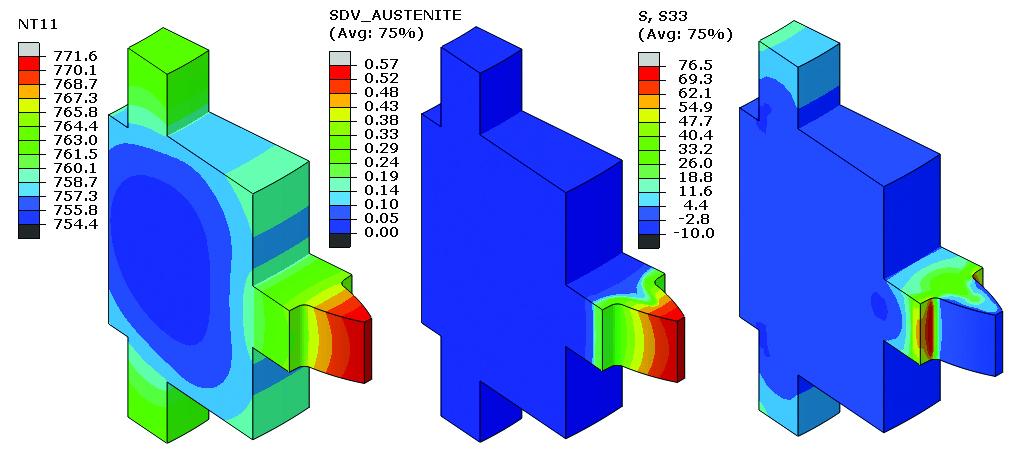
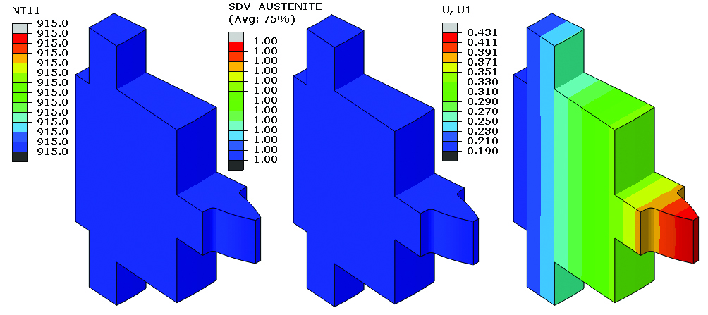
The heating process is modeled by applying a uniform heat transfer coefficient on the gear surface with the furnace temperature at 915°C. Figure 7 shows temperature, austenite, and circumferential stress distributions at 673 seconds during heating. The tooth tip has a higher heating rate, and the austenite transformation occurs earlier at the tip.
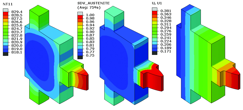
Figure 8 is a snapshot of the gear at 820 seconds during heating. The austenite distribution clearly shows the effect of carbon on the austenite formation. The growth of the gear due to heating is also shown.
At the end of heating, the gear temperature is 915°C, and it is fully austenitic. The radial growth is 0.431 mm.
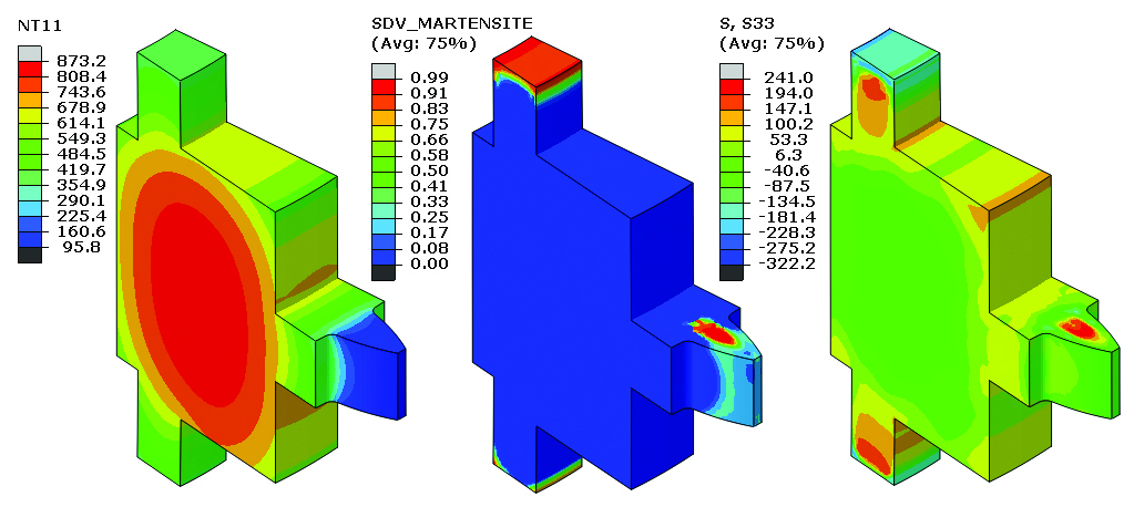
Using the predicted temperature from coupled AVL Fire and DANTE thermal model, the stress model of the quenching process is executed. Figure 10 shows the temperature, martensite, and circumferential stress distributions at 3.7 seconds during quenching. When austenite transforms to martensite, the material volume increases because martensite has a lower density. As shown in Figure 10, the region with martensite forming shows a compression stress, and its neighbor is under tension to balance the stress.
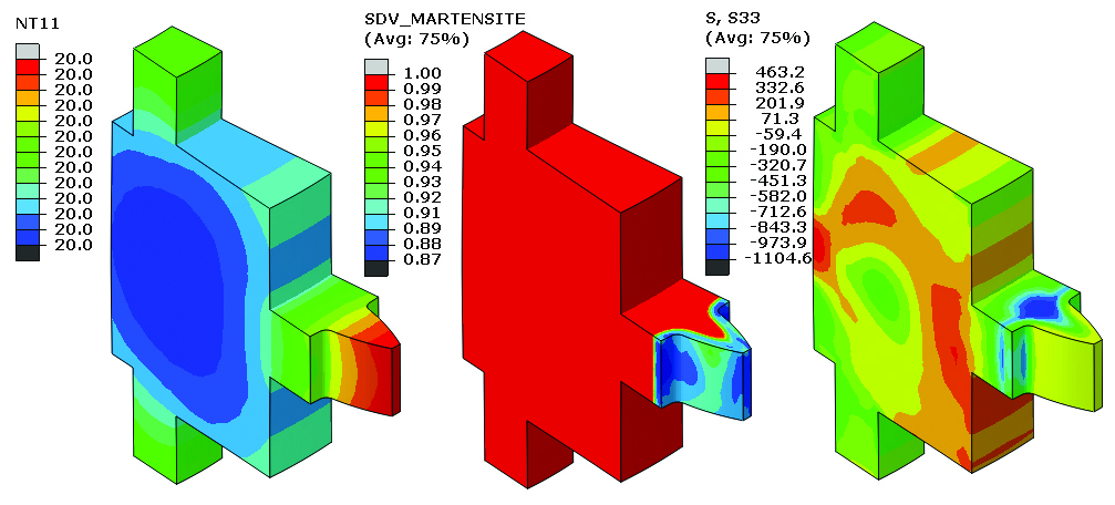
At the end of quenching, the volume fraction of martensite and residual stress in the circumferential direction is shown in Figure 10. Pyrowear 53 has high hardenability, and the austenite transforms only to martensite during quenching. The gear tooth is carburized, and the retained austenite at the gear tooth case is about 12 percent due to the lower Ms and Mf temperatures of the high carbon content of the case.
Conclusion
The applied CFD code AVL Fire is coupled with DANTE to predict the latent heat release, distortion, and residual stresses during the quench hardening process. The latent heating release has a significant effect on the temperature distribution during quenching, which will affect the rate of phase transformation, distribution, and residual stresses of the quenched part. The study shows the possibility of coupling CFD transient analysis with the heat treatment model of a solid part, which is valuable in understanding the cooling uniformity around the part and its effect on the part response during liquid quenching processes.
References
- R. Kopun, R., Greif, D., Zhang, D., Stauder, B., Škerget, L., Hriberšek, L., Advances in Numerical Investigation of immersion Quenching at Different Pool temperatures, SAE Brasil under revision.
- AVL List GmbH, Fire® CFD Solver, Eulerian Multi-fluid model. Solver Theory Guide. 2013, Graz, Austria.
- Srinivasan, V., Greif, D., Basara, B., On the heat and mass transfer modeling to simulate quenching heat treatment process, 6th International Quenching and Control of Distortion Conference, Chicago (2012).
- Greif, D., Kovacic, Z., Srinivasan, V., Wang, D.M., Suffa, M., Coupled numerical analysis of quenching process of internal combustion engine cylinder head, BHM Journal, Vol. 154 (2009).
- Jan, J., Prabhu, E., Lasecki, J., Weiss, U., Mulayim Kaynar, A., Eroglu, S., Development and Validation of CFD Methodology to Simulate Water Quench, Proceedings of the ASME 2014 International Manufacturing Science and Engineering Conference.
- Mulayim Kaynar, A., Eroglu, S., Weiss, U., Prabhu, E., Jan, J., Lasecki, J., Kopun, R., Greif, D., Experimental and Numerical Investigation of Water Quench Cooling of Aluminum Cylinder Heads, 5th International Conference on Thermal Process Modeling and Computer Simulation, June 16-18, 2014, Florida.


