Spray quenching involves the removal of heat by the impingement of a liquid quenchant on a hot metal surface. Examples include:
- Fog quenching.
- Quenching with water streams or water and polymer (induction hardening).
- High pressure jets of water or other quenchants (quenching of continuous coils of aluminum or steel).
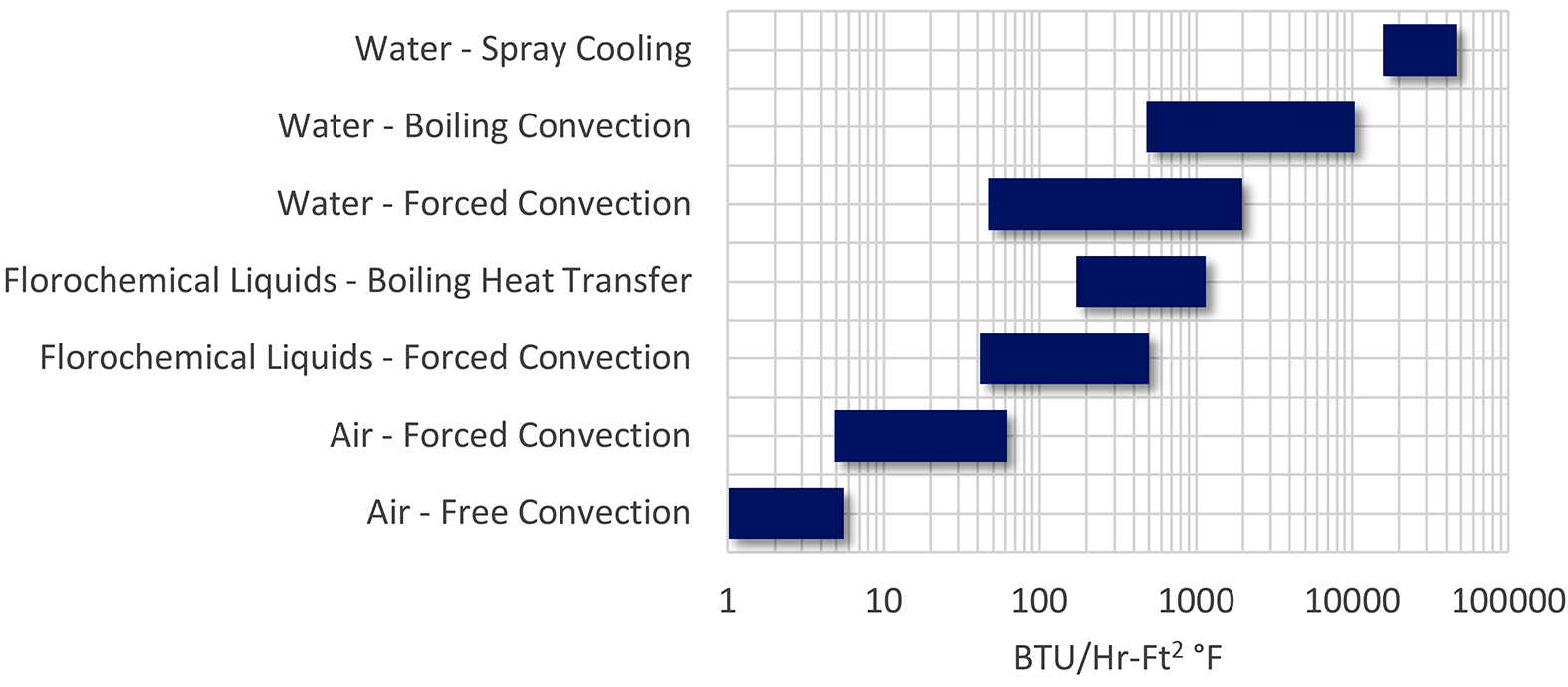
The basic methodology is also applicable to many other types of processes. Machining operations flood or spray a coolant to remove heat from machined parts (as well as providing lubricity). Seamless tubes that are heat treated are sprayed in a precise stream to effect proper quenching. This basic methodology is also used for HVAC in evaporative cooling. This methodology is also used for cooling of electronics. The range of heat transfer available is large compared to other methods (Figure 1).

Mechanism of Quenching
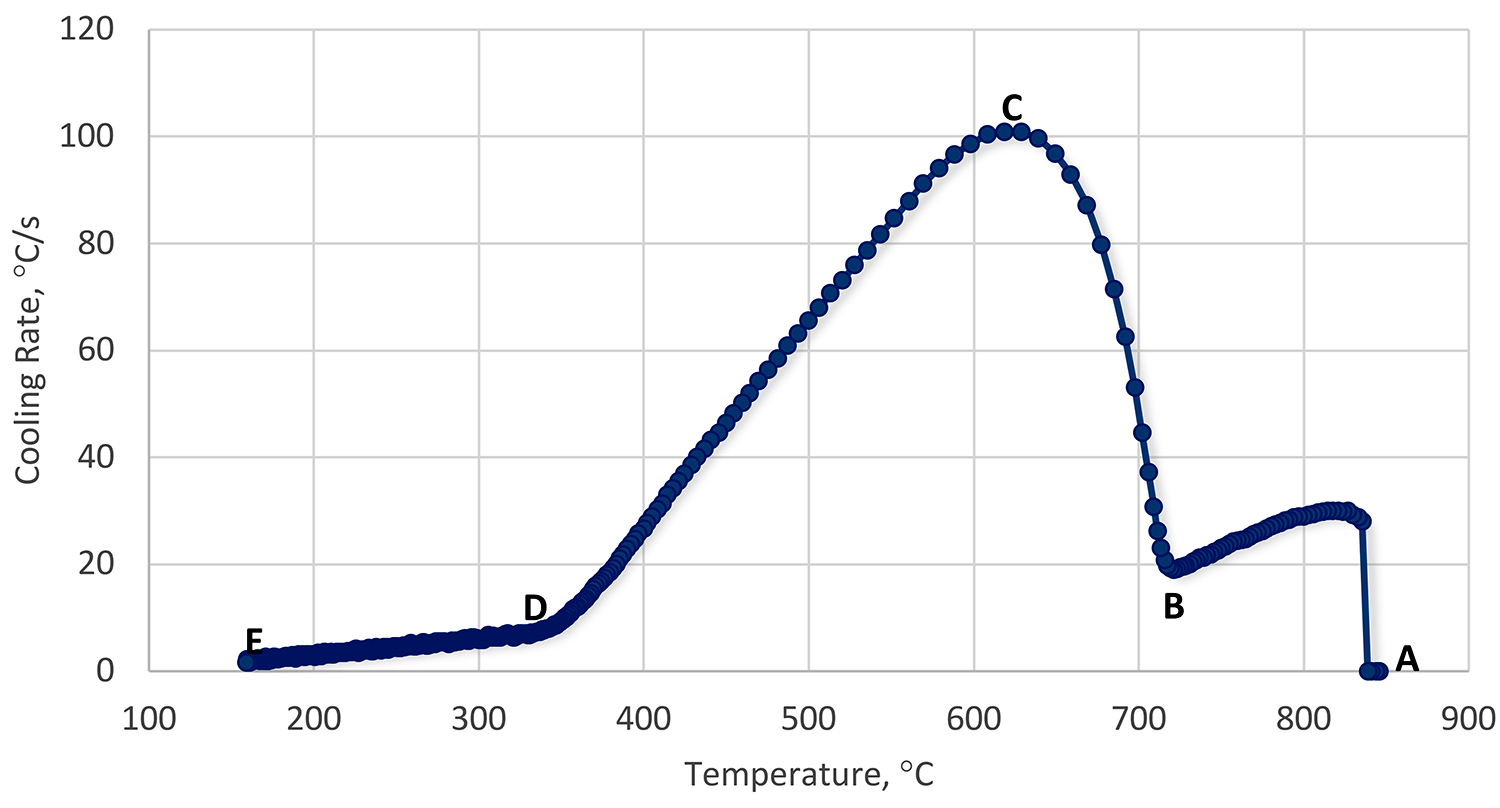
Like immersion quenching, there are three basic phases of quenching using a spray: vapor phase, boiling phase, and convection phase. However, while the phases remain the same, there are differences due to the mechanical aspects of the spray (Figure 2).

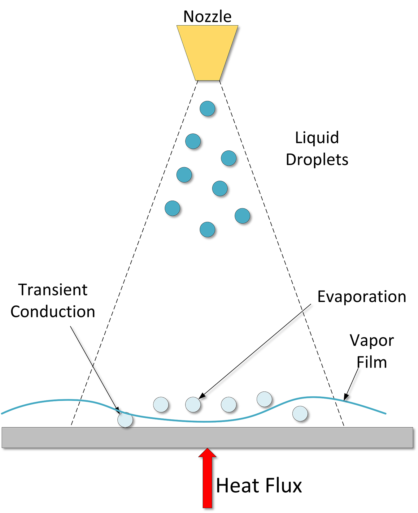
In the initial film boiling phase (Region A-B), heat transfer is slow, and a persistent film forms. Droplets form non-wetting spheres on the surface of the heated part and evaporate very quickly. This inhibits the impact of additional droplets. There is some transient conduction to the non-wetting spheres. As the temperature gradually falls, the film thickness decreases. Droplets with higher than average kinetic energy penetrate the persistent vapor film, and initial wetting of the part occurs (Leidenfrost Temperature – Point B).
The transition boiling regime (Region B-C) is characterized by a decreasing wall temperature and increasing heat flux. This is a mix of both boiling and vapor phases. Heat transfer is unstable, and the surface is wetted and unwetted, depending on the local heat flux.
As nucleate boiling becomes more dominant, and film boiling is less so, the heat transfer and heat flux increase. At some point, the heat flux reaches a maximum (Point C). This heat flux is called the critical heat flux, and is independent of the heated material, but dependent on fluid properties. First, as the part cools, at large wall superheat, the number of bubbles is large, and bubbles tend to coalesce vertically and horizontally. Very rapid heat transfer occurs (Region C-D). As the part cools, bubbles form at their own nucleation sites, and do not interact with each other.
Finally, as the part cools, when there are no more bubble nucleation sites, low wall superheat, then the convection phase forms (Region D-E). This regime starts when bubble formation ends. Understanding this relatively simple regime is quite complicated in spray cooling because of the motion of the liquid film on the surface of the part, and the impingement of new droplets, resulting in mixing. A schematic of the spray quenching mechanism is shown in Figure 3.

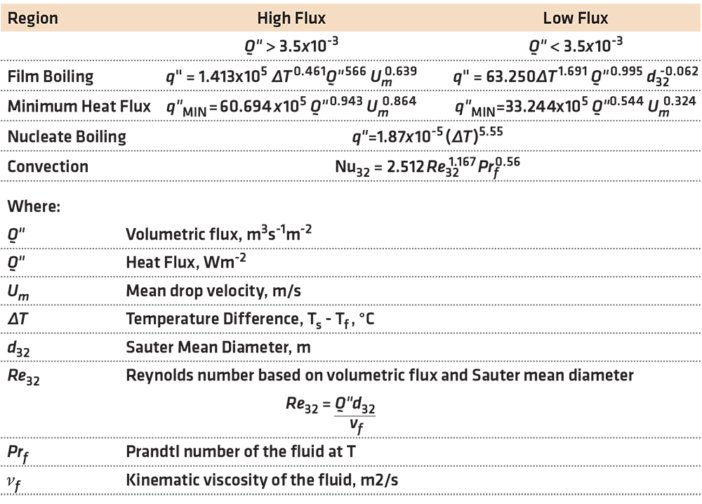
An examination of one elliptical and four different full-cone nozzles was conducted by Klinzing et al [2] and the authors determined that there were two distinct spray cooling regimes. This enabled the classification of sprays with respect to the volumetric flux. The low flux sprays where Q” (volumetric flux) was < 3.5 ↔ 10-3m3sec-1/m2 and the high flux sprays where Q” was > 3.5 ↔ 10-3 m3sec-1/m2. They determined that the drop velocity was only important for the high volumetric flux. Drop diameter was found to have a weak influence.
In this work, they developed many correlations for the various regions of the cooling curve, with an error of less than 20 percent. For the comprehensive list of the correlations, the paper is highly recommended. Some selected correlations are shown in Table 1.

These correlations are for vertical sprays directed downward on a plate. Different correlations are necessary for different geometries, such as a vertical plate or spraying upwards on a plate. The differences are due to different hydrodynamic conditions at the plate surface. For a vertical surface, there will be an asymmetric difference due to the fluids at the upper portion of the spray, falling down the surface of the plate, and heating as the drops are falling. In the case of a spray directed upwards, the liquid falls away from the plate surface due to gravity. This is one reason that heat transfer on the upper surface of a plate is higher than the lower surface by 10-20 percent.
Conclusion
In this column, we described the mechanism of quenching during spray quenching and provided a limited number of correlations for spray quenching using cone-type spray nozzles. The reader is directed to the reference section and the paper of Klinzing et al [2] for additional correlations.
Should you have any questions on this column, or suggestions for any further columns, please contact the author or editor.
References
- M. Jafari, “Analysis of Heat Transfer in Spray Cooling Systems using Numerical Simulations,” Windsor, Ontario, Canada, 2013.
- W. P. Klinzing, J. C. Rozzi and I. Mudawar, “Film and Transition Boiling Correlations for Quenching of Hot Surfaces with Water Sprays,” J. Heat Treating, vol. 9, pp. 91-103, 19925.


