


Sinter-based additive manufacturing (S-BAM), of which Binder Jet AM (BJAM) is one approach, is quickly becoming recognized as one of the most desirable methods to produce high-volume 3D printed components and to develop new 3D printable materials. Although the S-BAM technique of printing has been available for a while, the optimal processing parameters, such as the time to de-bind and sinter, must be better understood for the full advantage of this method to produce high-volume components to be realized.
The first step in the optimization of the process is to understand the binder and its function. Thermal Gravimetric Analysis (TGA) results are used to determine how the binder breaks down and at what temperature the optimal de-binding process should be performed. Along with this, the functionality of the binder will be considered to determine the importance of thermal ramp rates.
Through time-stop studies, printed 17-4 stainless steel components of varying thicknesses will be analyzed for binder removal. This provides an understanding of the de-binding steps as a function of time and allows for the optimal time for de-binding as a function of the components thickness to be determined. This information can then be used to optimize the BJAM process, advance production rates, reduce cost, and improve product quality.
Background
Sinter-based additive manufacturing (S-BAM), specifically Binder Jet Additive Manufacturing (BJAM), is not a new technology. For a long time, the printing of metal by BJAM has been considered the “ugly stepchild” of the metal printing world. Over the past few years, this has changed, as the desire to print reactive metals and high-volume components has come to the forefront of the industry. BJAM of metal has a much higher throughput than energy-based technologies and can print materials that cannot be welded.
As Gonzalez-Gutierrez et. al. show in Figure 1 [1], the S-BAM process fits well within the already existing MIM process. Metal Injected Molding (MIM) producers have been the quickest to adopt S-BAM to produce complex components due to these similarities.
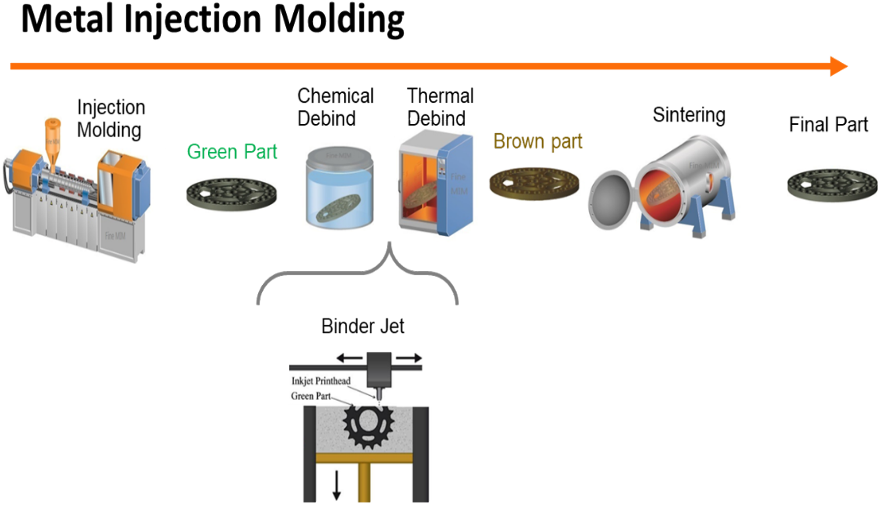
Unfortunately, the lack of understanding of the metal BJAM process has resulted in a great lack of efficiency in the S-BAM process. One of the most pressing current issues is that MIM producers use the same ramp rates, temperatures, and soak times used to produce MIM components; however, parts produced using the BJAM process are different.
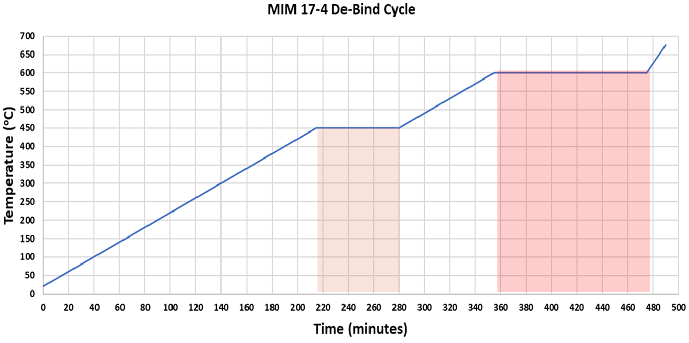
Four parameters can be varied during the de-binding, including the heating rate, temperature, hold time, and process atmosphere. Figure 2 illustrates a typical cycle used to produce MIM components. The ramp rate is typically 2°C/hour, which makes up 275 minutes of the process. There are two hold times, 450°C and 600°C, respectively, that make up the remaining 195 minutes of the total 470-minute de-bind cycle. This cycle though, needs significant modification to best-fit de-binding of parts produced using BJAM.
Ramp rate
Ramp rate is determined by the need for one step to happen before another takes place. For example, in the MIM de-binding process, the binder must have room to expand, melt, potentially boil, and travel out of the part. The pathways for the binder constituents to exit are limited because all the space between the particle is occupied by the binder to hold the components together. For this reason, heating too quickly will result in the binder expanding faster than space or pathways allow, causing pressurization of the internal component and potential cracking. Here lies the reason for a very slow thermal ramp rate, 2 Co/hour, in the MIM process.
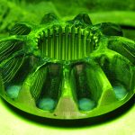
This is not the case in a metal component printed using the BJAM process. As Figure 3 shows, the metal particles are held together by small pendants of binder that connect the particles. In the SEM/EDX elemental mapping in Figure 3 [2] of a stainless steel component printed using the BJAM process, only carbon is shown where the binder is present because there is minimal carbon in the stainless steel material, and the binder is a hydrocarbon.
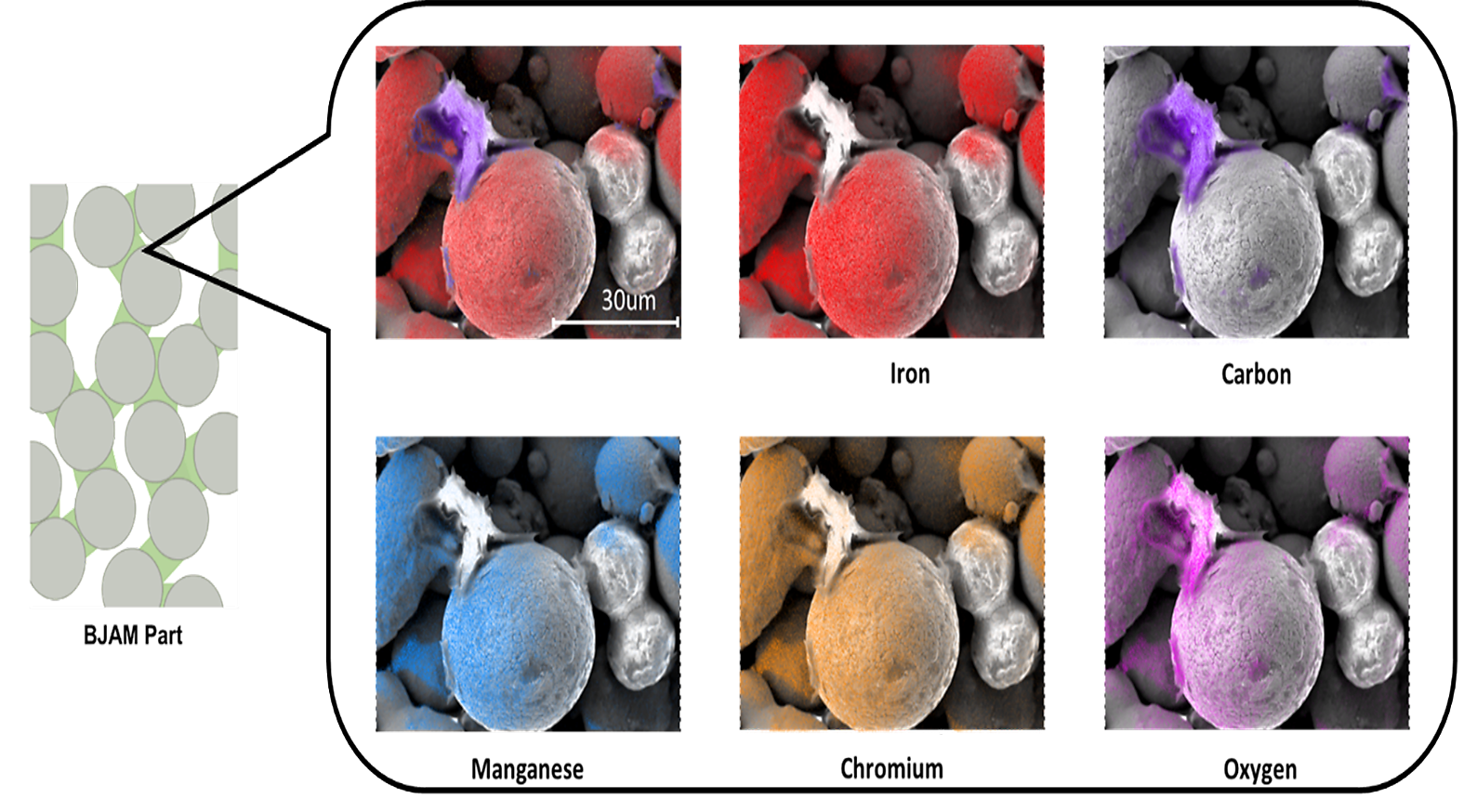
It is important to note the large amount of space open between the particles in Figure 3. These are open pathways and space for the binder to expand, vaporize, and exit the part. Because there is much more space between the particles and much less binder than in MIM components, the need to use an extremely slow ramp rate is not necessary for components printed using BJAM.
In all the testing to follow, a ramp rate of ~15°C/hour was used. No micro-cracking or otherwise detrimental effect was seen in any of the components. This means ramping for S-BAM components can be increased by almost 8X, significantly reducing the overall cycle time to remove the S-BAM binder.
Temperature
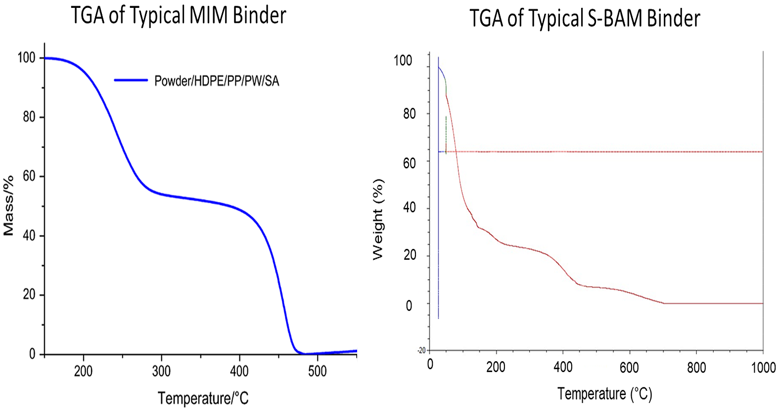
MIM binder and BJAM binder are not the same. Figure 4 shows the TGA analysis of a typical MIM binder and S-BAM binder. The temperature where the MIM binder begins to lose weight is much higher than that of the S-BAM binder. Likewise, the steps in each TGA do not match. This illustrates the hydrocarbon cycle for a MIM binder is significantly different from an S-BAM binder, not only where it begins but throughout the entire de-binding cycle.
Since the MIM binder is so different, one must look at the S-BAM binder independently to determine the optimal thermal cycle for its removal from binder jetted components.
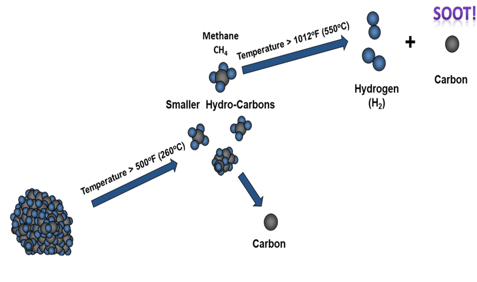
From previous work by Feldbauer and Levanduski, Figure 5, a simple model to describe the “unraveling and sooting” of a hydrocarbon can be applied to the TGA for the S-BAM binder.
The Feldbauer-Levanduski mechanism identifies two key temperatures. The temperature 260°C where the hydrocarbon begins to “break-down” into smaller hydrocarbons and 544°C (shown as 550°C in the illustration), the temperature where the hydrocarbon will dissociate to form hydrogen and carbon. The hydrogen is a gas; while the carbon is a solid and remains behind in the component at “soot.”
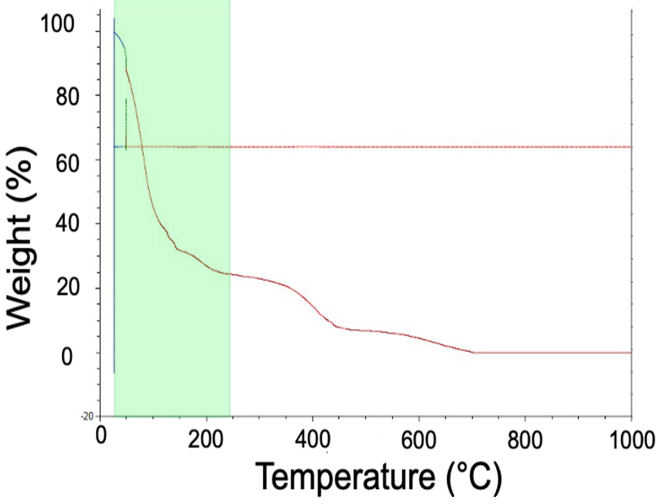
Considering the Feldbauer-Levanduski mechanism in conjunction with the TGA results for the S-BAM binder, the TGA of the S-BAM binder can be considered as having three zones.
The first zone is highlighted green in Figure 6. Between room temperature and 250°C, the solvent base of the binder evaporates. We know it is a solvent-based binder because the weight loss begins well below the boiling point of water, 100°C.
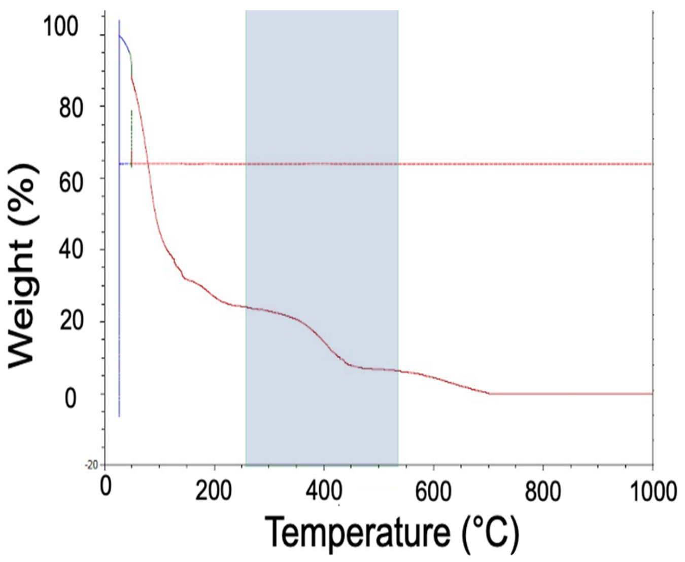
Considering the second zone of the TGA data (Figure 7), it is evident that, between 260°C and 544°C, there is a reduction in the weight associated with the hydrocarbon of the binder “unraveling” to form more simple hydrocarbon chains.
It is important to note that, from the applied mechanism, there is a small amount of carbon that does drop as the binder hydrocarbon chains break down. Without the addition of some type of oxidizing source to react with this small amount of carbon, some carbon will remain in the component.
In the third zone of the TGA (Figure 8), above 544°C, the hydrocarbon will dissociate into hydrogen and carbon. This is why the curve shows a loss of weight; however, it plateaus to the final weight of the solid carbon that is left behind.
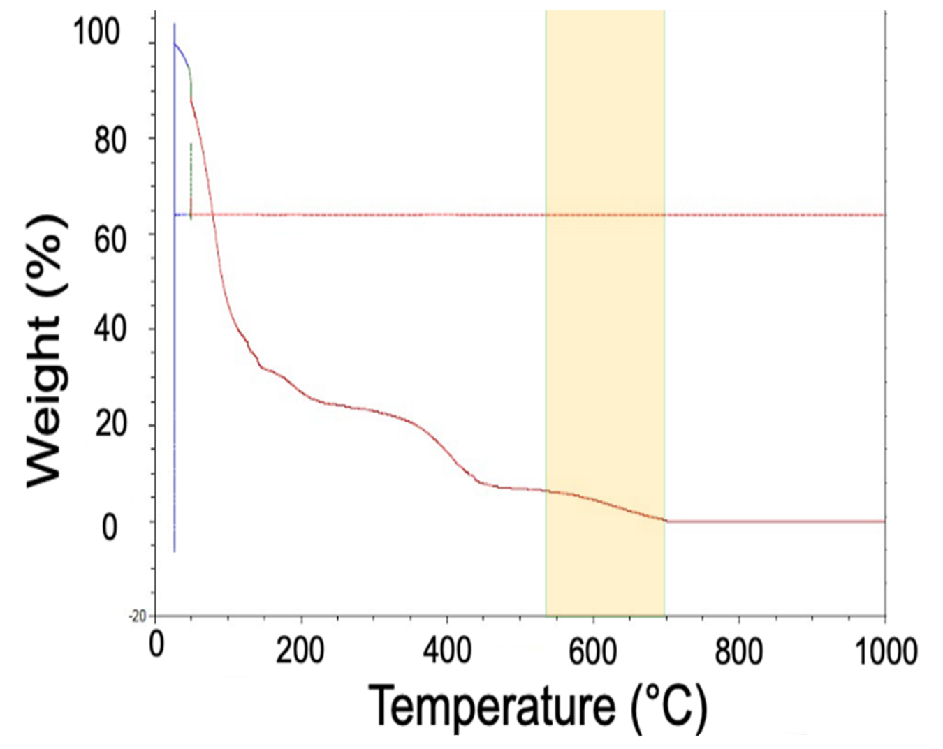
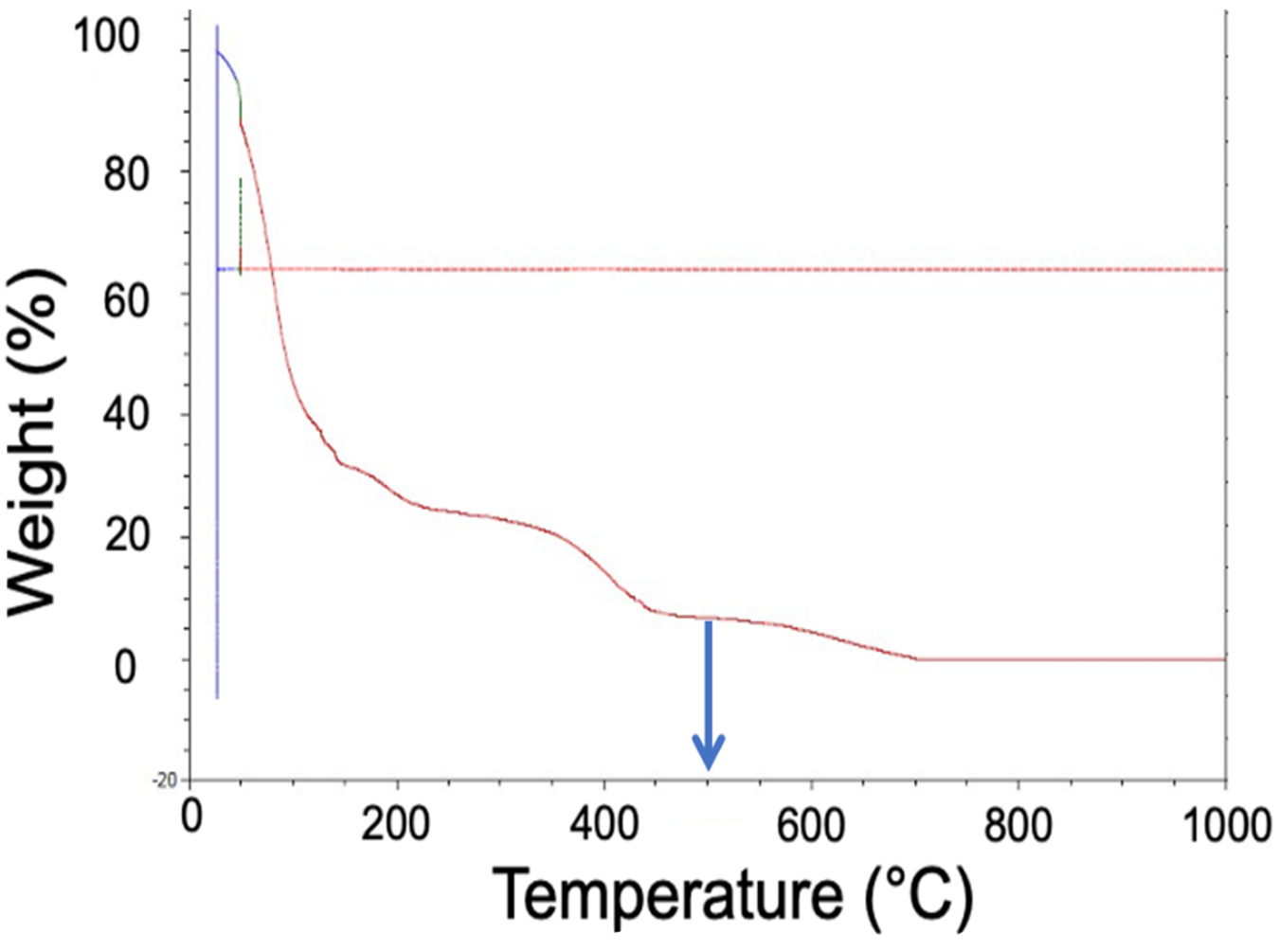
It is important to avoid this third zone while de-binding. If the de-bind temperature is too high and solid carbon is formed because of the dissociation of the binder, the chemistry, degree of sinter, physical properties, and corrosion properties of the final product may be negatively affected. For this reason, Figure 9 shows the optimal temperature for removing the S-BAM binder is 500°C. At this temperature, the hydrocarbon will completely “unravel” without dissociating and depositing additional carbon inside of the component.
Time
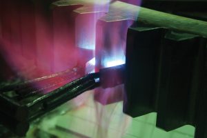
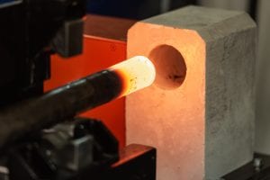
Time-stop studies were conducted to determine the optimal amount of time needed for removal of the S-BAM binder. Samples of 17-4 binder-jet printed to thicknesses of 1/4”, 1/2”, 3/4”, and 1” were placed in a basket, as shown in Figure 10.
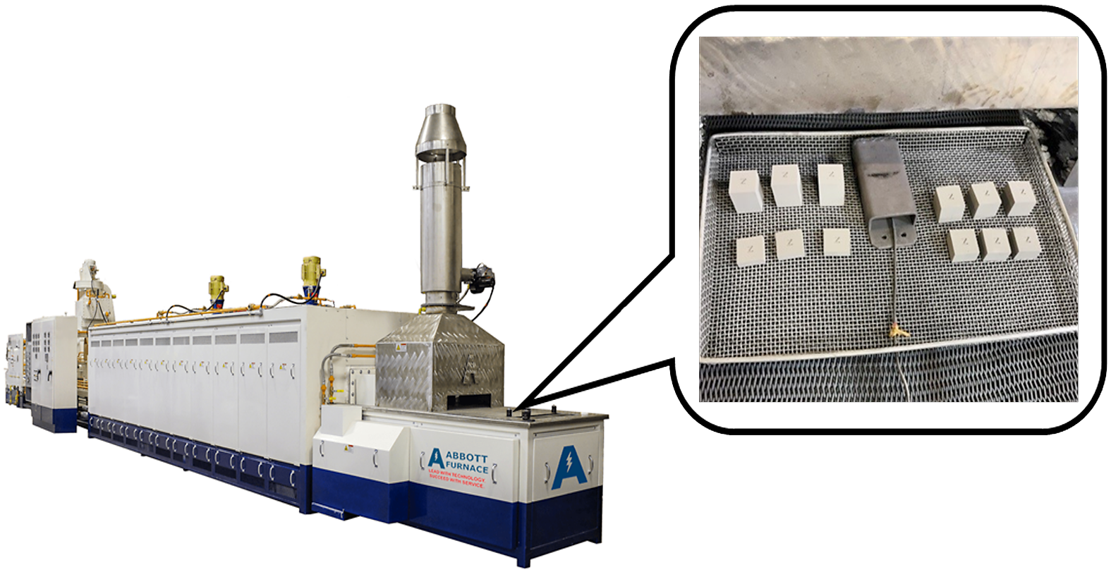
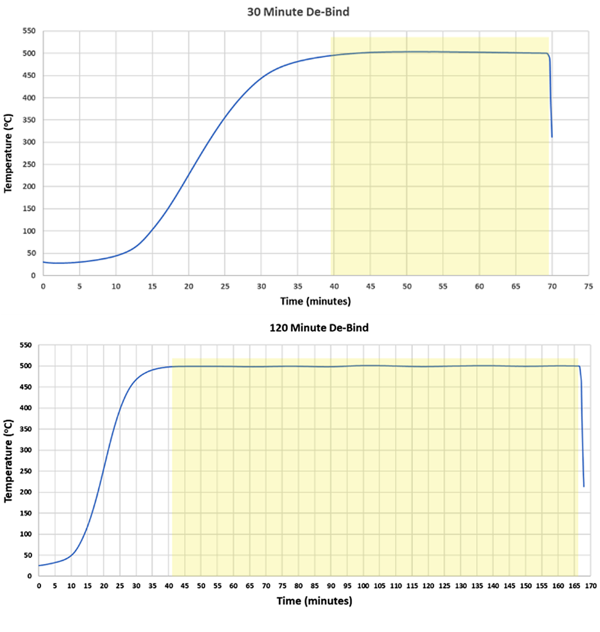
Each test was instrumented to allow the collection of the profile and ensure the de-bind time was accurate. A collection of all sizes was then heated at a rate of ~15°C/hour to 500°C and soaked (Figure 11). A set of all thicknesses was then pulled at 30 minutes, 60 minutes, 90 minutes, and 120 minutes.
The samples were then inspected for cracking and micro-cracking. No evidence of cracking at this heating rate was found in any of the samples, confirming the ability to increase the ramp rate.
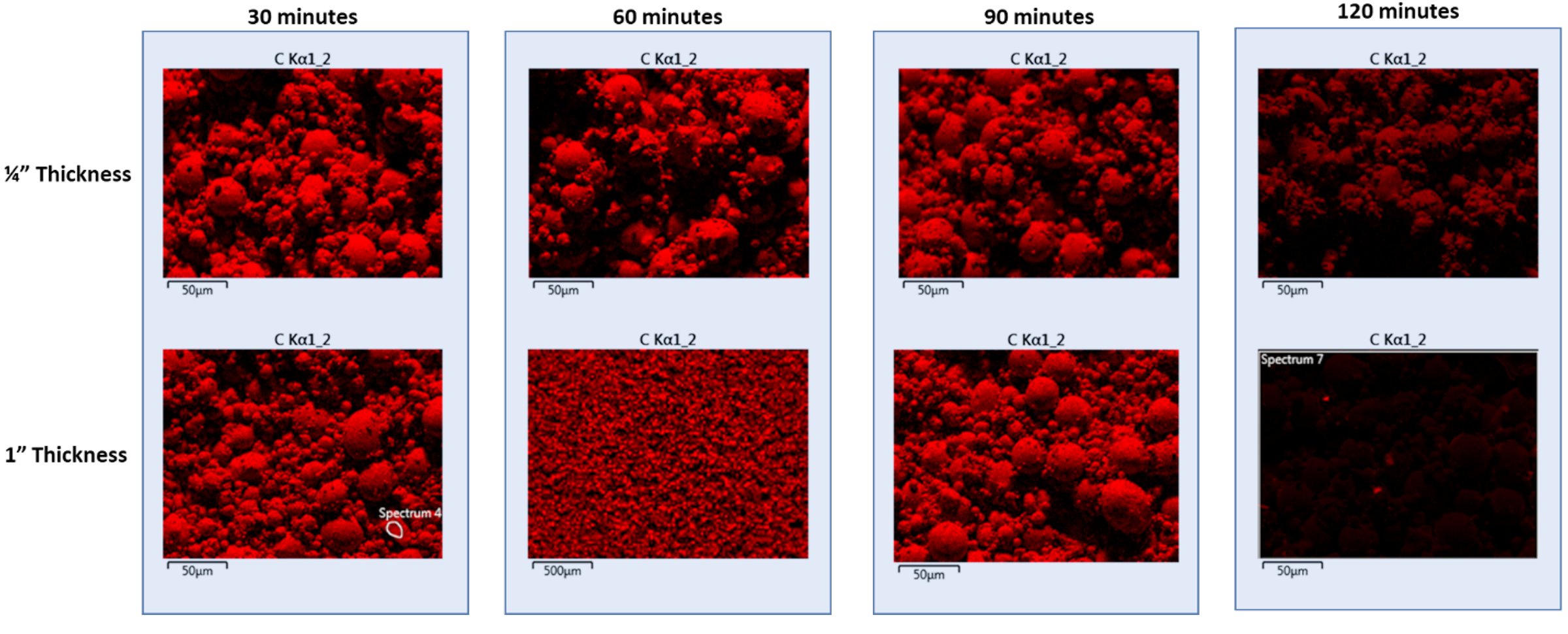
Samples were then sectioned, and an SEM/EDX analysis was performed. Figure 12 shows the EDX map for carbon in the 1/4” and 1” thick samples. A distinct change in the amount of carbon is present when comparing 120 minutes at 500°C to the other times, demonstrating the time needed to remove the binder is 120 minutes. There is a small amount of carbon still visible at 120 minutes; however, it is important to note:
There is a small amount of carbon dropped during the breakdown of the hydrocarbon between 260°C and 500°C.
17-4 contains carbon as part of its original chemistry.
The critical point for de-binding is that the center of the component reaches the target de-binding temperature of 500°C and is held for 120 minutes.
Atmosphere
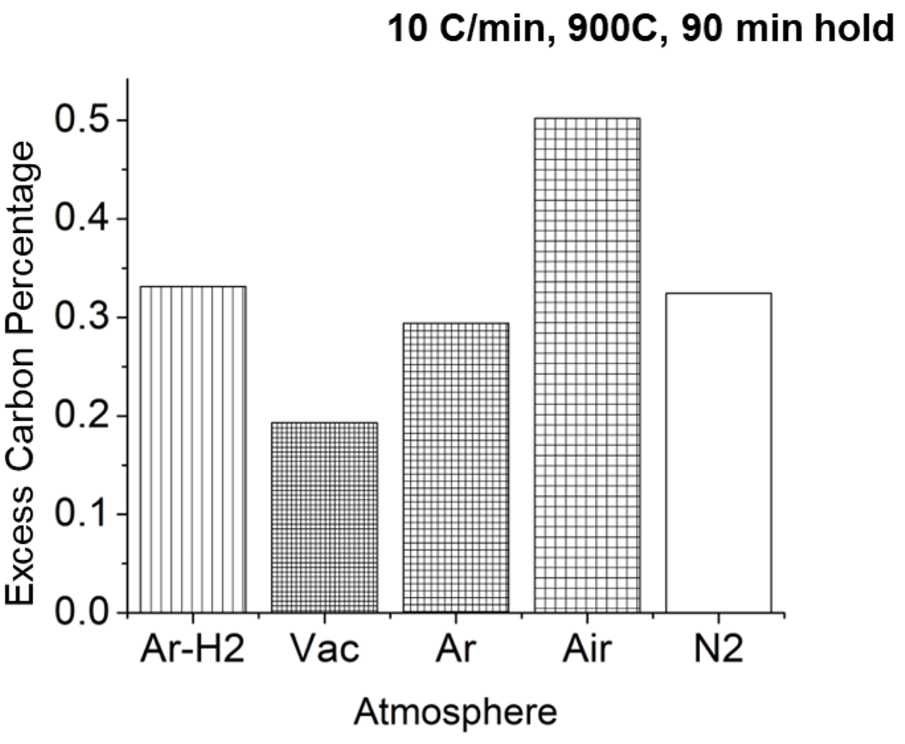
An initial evaluation of the de-bind atmosphere was conducted on BJAM-printed H13 material. H13 was chosen because it does not contain carbon in the base chemistry of the material. The carbon level following the de-bind cycle could then be compared for various atmospheres to determine what atmosphere would be optimal.
As seen in Figure 13, the best atmosphere was shown to be a vacuum. The argon/hydrogen, pure argon, and pure nitrogen atmospheres were next best. This is because the vaporous hydrocarbons that form as the binder breaks down are pulled from the furnace while the others sweep the gases away. The air tends to react with the binder to limit the removal of hydrocarbon that then soots.
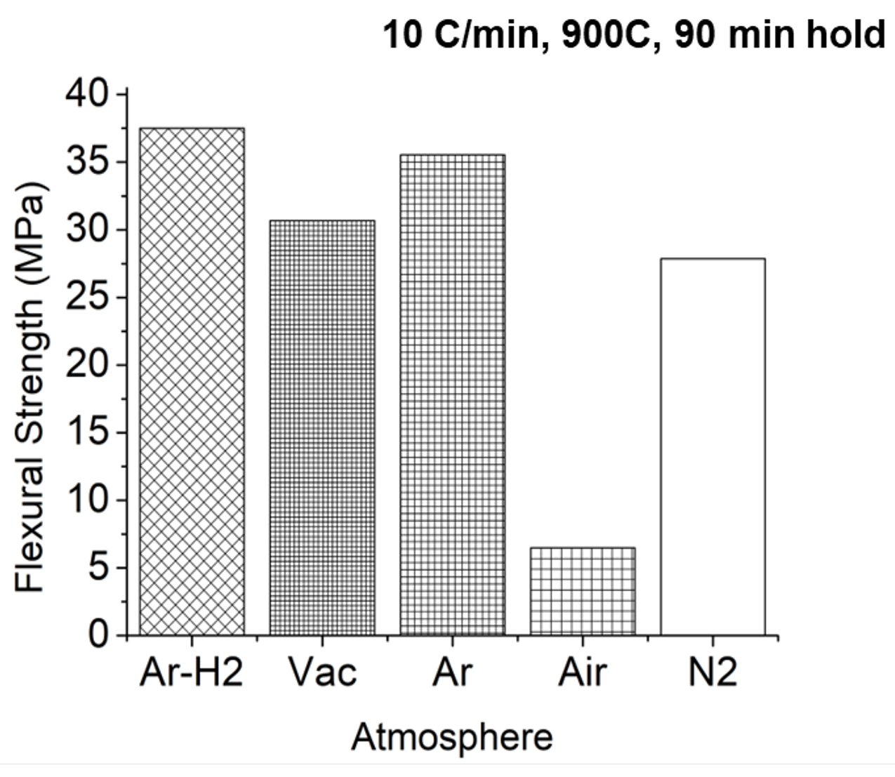
However, carbon is not the only consideration with respect to atmosphere. A further look at the flexural strength of the component shows that the argon/hydrogen and pure argon atmospheres delivered the result (Figure 14). Again, air is much worse.
Argon/hydrogen and purge have proven to be equally viable as a good atmosphere for the de-binding of sinter-based additive manufactured components; however, there is one other consideration: cost. Given that argon is typically twice the cost of hydrogen, a hydrogen/argon or purge argon blend, when possible, would be best.
Conclusions
Sinter-based additive manufacturing is rapidly becoming the future of additive manufacturing; however, for it to reach its full potential, the initial adopters of these technologies must realize the de-binding thermal ramp rates, temperatures, hold times, and atmospheres from the MIM process are not optimal for the S-BAM process, and BJAM of 17-4 components, specifically.
A review of each of the key components of the removal of S-BAM binder used in the BJAM printing of 17-4 was conducted. The optimal conditions were determined to be:
• Thermal ramp rate of ~15 Co are acceptable. This results in an 89 percent improvement in efficiency over a typical MIM cycle, reducing the ramp time from 275 minutes to 30 minutes.
• The optimal de-bind temperature is 500°C. Typical maximum temperatures used in the de-binding of MIM are too high and will result in increased carbon in the final material.
• Only one soak is needed.
• The optimal soak time is 120 minutes. This results in a 39 percent improvement in efficiency over the typical MIM cycle, reducing the hold time from 195 minutes to 120 minutes.
• Hydrogen is the best atmosphere.
When the above optimizations are combined, the process described for the de-binding of the S-BAM binder is 68 percent more efficient than a MIM approach.
Sinter-Based Additive Manufacturing fits well within a MIM facility because much of the equipment is similar; however, it is important to note that S-BAM is not MIM. They are different processes and must be treated as such to obtain the highest quality, production, and cost-effectiveness in both processes.
References
- Gonzalez-Gutierrez, J. S. (2018). Additive Manufacturing of Metallic and Ceramic Components by the Material Extrusion of Highly-Filled Polymers: A Review and Future Perspectives. Materials, 11 (5): 840.
- Gilmer, D., Han, L., Hong, E., Siddel, D., Kisliuk, A., Cheng, S., … & Saito, T. (2020). An in-situ crosslinking binder for binder jet additive manufacturing. Additive Manufacturing, 35, 101341.
- Matula, G. e. (2018). Application of thermal analysis in the selection of polymer components used as a binder for metal injection moulding of Co–Cr–Mo alloy powder. Journal of Thermal Analysis and Calorimetry, 391-399.


 general practice for CQI-9 and AMS2750E")


