


This article deals with novel hybrid layers combining hardfacing and nitriding to improve forging tool durability. It includes a study of the nitriding capabilities of hardfacings made of typical materials used to repair key groups of hot forging tools. Tests were conducted on samples and on tools in forging processes. Tests on samples included hardfacing, nitriding, microstructure, microhardness, XRF-phase analysis, and abrasive wear tests. Experimental tests on forging tools included operational tests and comprehensive wear analysis by scanning, macroscopic, and microscopic observations by light and scanning microscopy, and analysis of wear mechanisms. Tests on the samples confirmed the positive effect of nitriding on performance properties at room and elevated temperatures. They revealed the reduced susceptibility to nitriding of some welds and the variable composition of nitrides present on the surface of the samples, which has a key effect on the observed wear mechanisms in the ball-on-disc test. Operational tests showed the effect of improved durability, which is greatest for the DO*15 (Fe–Cr–Mo–W) + nitriding layer, which is due to the increased hardness of the weld itself and the increased susceptibility to nitriding.
1 Introduction
In a production process, tool wear is one of determinants in terms of its effectiveness.
Among manufacturing processes, plastic forming processes, including hot die forging, are a specific group that has a quality of low tools’ durability. Tools used in them are usually complex, thus, expensive to make, and that, in some cases, increases their costs up to 30 percent of the total production expenditure. Low durability of forging tools is due to the harsh operating conditions to which these tools are exposed. In hot die forging processes, three main factors cause tools’ destruction. These are: intense heat shocks, mechanical load changing cyclically, and intensive friction [1]. As a result, during work in the upper layer area, some destructive mechanisms occur. Recent research indicates the top layer of matrixes has the following wear mechanisms: abrasive wear, heat and mechanical fatigue, plastic deformation, fatigue cracking, adhesive wear, and oxidation [2, 3].
Many methods are used to improve the longevity of forging tools in manufacturing. The steps toward improving tools’ durability are usually taken in three main directions. The first method considers both technological and structural aspects of the forging process. The second direction focuses on modification of the material from which the tools are made. The last tendency is modern surface engineering. The group of the most common techniques include welding (pad welding), heat and chemical treatment (nitriding, nitrocarburizing), beam techniques, mechanical methods (ball-burnishing), and hybrid layers and techniques. There are no clear criteria for selecting the methods adopted for improving tool life, as each case should be analyzed separately for the conditions during the forging process [4].
However, nitriding is currently the most popular method of improving the resistance of forging tools. Numerous observations of industrial forging processes with nitrided tools have shown this treatment allows to prolong their life several times. The latest nitriding methods, thanks to precisely chemically controlled nitrogenous atmosphere and nitrogen potential, allow to obtain nitrided layers of any structure. An example is the ZeroFlow method, developed by Prof. Leszek Małdziński from the Poznań University of Technology, and is used by Seco Warwick company [5]. In this method, the nitriding process uses a one-component atmosphere consisting only of ammonia (NH3) dissociated inside a retort furnace, whose concentration determines the amount of nitriding potential.
Pad welding, increasingly popular, is another answer to the issue of durability. Surfacing is associated with changing the properties of the top layer, in particular preventive surfacing. This method requires covering forging tools, using welding with a metal layer while melting the substance. Observations of forging tools teach that, in some cases, pad welding increases their durability [6]. Many surfacing techniques differ in a padding weld material, which may have a composition and properties similar to tool steel or higher hardness and wear resistance [7]. At times, methods such as a flame or plasma spraying, laser processing by surfacing [8], spraying [9], plasma spraying [10] or hardening the surface [11] are also used to regenerate and improve the surface of dies. Recent studies discuss the use of laser beam powder melting (LBM) for the construction of forging tools in additive technologies [12].
Regenerative pad welding is widely used to repair machine parts that have undergone various types of wear. Preventive (protective) surfacing, which provides a protective layer with greater wear resistance from the beginning of use, is used in a similar way.
Enhancement to durability of forging tools, using new hybrid layers combining surfacing and nitriding, is not widely discussed in the scientific literature. However, combination of these two types of working is noteworthy, because it releases new potential and gives other possibilities. Available literature says little about prospects of using hybrid surface layers, obtained from the combination of surfacing with nitriding, to increase durability of forging tools. Nevertheless, there are works on nitriding of inguinal joints, welded machine parts [13], surfacing and nitriding of internal combustion engine valves [14], and even intentional surfacing and nitriding of the steel structure elements [15]. They point to increased corrosion resistance, tribological resistance, and greater mechanical strength of such layers.
In recent years, the authors carried out research on application of layers combining MIG powder wire welding with subsequent processing of the layers infused by gas nitriding. The results indicate significant increase of durability in hot forging processes [16]. Tests of mechanical properties and microstructure of these layers were also performed. They showed an increased resistance to abrasive wear, beneficial effect of nitriding on transformations occurring in the microstructure of padding welds, and favorable compressive stresses in the surface layer, which improve the fatigue strength of these layers [17]. Analysis has also shown different susceptibility to nitriding of padding welds, which, depending on the content of chromium and other alloying additives, are receptive to nitrogen diffusion [18] to various degrees. The authors have also pre-examined this technology in industrial environment and received durability increased by 300 percent compared to nitriding or surfacing used separately [19]. The satisfactory results and understanding of wear processes present in many industrial processes encourage the application of this method in numerous manufacturing applications.
Tools used in industrial forging processes can be combined into groups of tools of different purposes and different working conditions, including:
Forging dies on hammers: Bulky, weighting approximately 100-2,000 kilograms, with an amplified impact strength, and therefore, its hardness reduced to 35-40 HRC. This is because they are subjected to dynamic loads with the ability to work at temperatures up to 500°C.
Small dies and forging inserts on presses: Medium size and weight in the range of 10-100 kilograms, average impact strength and hardness approximately 40-50 HRC and work capacity up to 600°C.
Trimming tools and punches: Medium size and weight in the range of 10-100 kilograms, low impact strength and hardness approximately 50-60 HRC and ability to work at up to 600°C.
Each of these groups, owing to different requirements for materials and thus a significantly different alloy composition, has a dissimilar responsiveness to nitrogen diffusion in steel. Therefore, the tests were performed in three materials representing these three groups of popular applications. The tests aimed to practically verify and assess the possibility of padding welds nitriding in relation to various types of padding welds, their usage, different geometry, and chemical composition. The predominant goal was to isolate the main target groups among the materials used for padding welds. The effectiveness of the nitriding processes depends on their receptiveness to nitrogen diffusion in metals and their alloys. Nitriding of medium- and high-alloy steels is different from nitriding typical low-alloy steels. Therefore, nitriding can take longer, and the layers obtained from it will have lower thickness and hardness. Determining the susceptibility to nitrogen diffusion may require trials and tests performed on samples representing the most popular groups of materials for padding welds [20].
Another key task is to adapt to treatment in higher temperatures. This is how nitriding processes are usually carried out. For example, tool steels for cold operation should be nitrided at temperatures reduced to about 300-400°C to avoid tempering [21]. Likewise, low-alloy steels require a decrease in nitriding temperature. Nitriding as heat treatment has an impact on the microstructure and properties of padding welds. Therefore, it can be considered as an additional heat treatment. This may be very beneficial for obtaining specific mechanical properties, changes in microstructure, and relaxation of after-welding stresses. Lack of such operation (due to savings or difficulties in carrying it out) contributes to earlier decay, because cracks are initiated at the site of non-relaxed welding stresses.
The last of the principal matters is the effect of nitriding on the possibility of a future re-regeneration by surfacing. Practice teaches that in such a case, the top layer is enriched with nitrogen thanks to nitriding. This nitrogen during next welding can then get into a padding weld and cause welding defects. This occurs when the nitrided layer is not removed by abrasive wear, especially in some alloy steels. Use of the so-called buffer layers or removal of the nitrided layer before the next pad welding can solve this problem. This, however, is demanding owing to the high hardness of the nitrided layers.
To sum up, apart from the unquestionable advantages, there are obstacles associated with the limited padding welds responsiveness to nitrogen diffusion, which should be overcome. It is necessary to skillfully conduct thermal processes so as not to temper excessively but only to relax welding stresses. In addition, the subsequent removal of the nitrided layer, which can be difficult due to its high hardness and thus low machinability, should be considered, too. This study researches the use of several welding materials for building padding welds, which were then nitrided. Nitrogen diffusion susceptibility was tested, and changes in microstructure and the effect of padding welds nitriding on their performance were also examined.
2 Materials and methods
The research aimed to determine the susceptibility of the padding welds, dedicated to the three groups of forging tools described in the introduction, to nitriding. In the first place, laboratory tests were carried out on samples, then for the selected tool, operational tests were performed in industrial conditions.
2.1 Samples and tools preparation
Samples for laboratory tests were prepared in a manner that would serve as a model of the forging tools production. The base part of each sample was a 100 ↔ 100 ↔ 50 mm cube made of X37CrMoV5-1 (1.2343 or H11) steel, heat treated by hardening and high tempering for hardness approx. 450–500 HV0.1. This is a typical hot processing of forging tools used in hot die forging. On this substance, three welded layers used the FCAW-S (self-walled powder wire) method with the following materials:
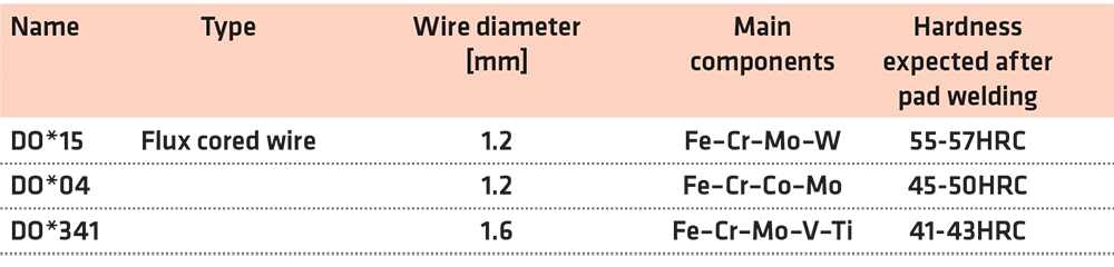
DO*15, Fe–Cr–Mo–W: As a material dedicated to surfacing of trimming tools and punches as well as dies and die inserts for forging on presses.
DO*341, C–Cr–Ni–Mo: As a material dedicated pad welding forging dies on hammers and large die inserts.
DO*04, Fe–Cr–Co–Mo: As a material dedicated to surfacing dies and die inserts for forging on presses.
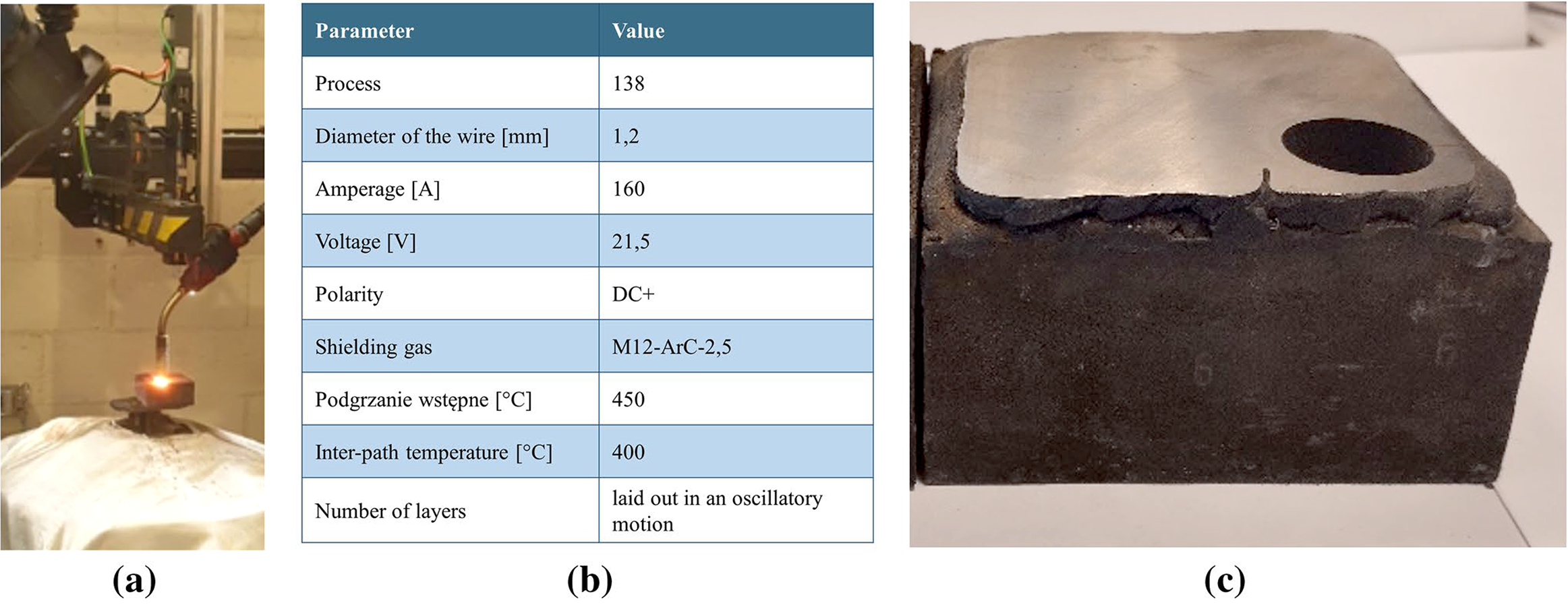
Because the welded materials are classified with limited weldability, it was necessary to select the appropriate parameters of the surfacing process each time. Moreover, this process required using appropriate heat treatments carried out before — during and after the surfacing. For instance, the pad welding was preceded by previous heating of the material to 400-450°C, and the appropriate inter-layer temperature (~ 350-400°C) was maintained during the process of surfacing, and after welding, each sample underwent tempering (~ 400°C, over 5 hours) and cooled in the furnace to avoid cracks in the padding weld. To achieve the highest quality and repeatability, tests were conducted at automated welding stations at Castolin in line with the parameters given in Table 1.

After pad welding, the surface of the samples was machined, and they underwent the ZeroFlow gas nitriding process with low potential so as to obtain a diffusion layer without continuous nitrides on the surface. The nitriding was carried out at a temperature of 550°C, over approximately 13 hours.
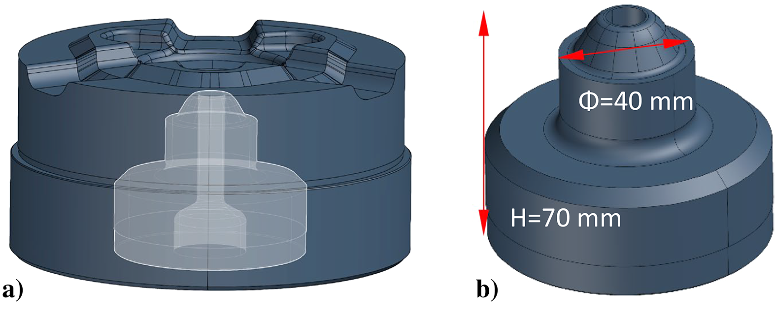
Operational tests, in industrial conditions, were performed for a selected forging tool, which was a forging punch made of X37CrMoV5-1 (1.2343 or H11) steel (Figure 1). Research was conducted on two punches that were hardfaced with various materials: DO*04, Fe–Cr–Co–Mo and DO*15, Fe–Cr–Mo–W. These materials are dedicated for use on stamps and forging dies on presses. After pad welding and processing, the tools were nitrided by the ZeroFlow method with the same parameters as the samples to obtain a diffusion layer, without a continuous nitrides layer on the surface.
2.2 Samples and tools testing
Prepared samples and tools after operational tests underwent laboratory tests. Sample’s studies included:
• Analysis of the chemical composition of padding welds under the SPECTROTEST mobile emission spectrometer with a module for analyzing the chemical composition of alloys based on Fe.
• Examinations of the microstructure, done using a Keyence VHX-6000 digital microscope with magnification up to 1,000X, with the capability of measurement under a variable lighting angle, depth of field composition in 2D and 3D, HDR-plus technology, in which photographs of the microstructure were taken. The microstructure in the nitrided layer, padding weld, heat-affected zone, and native material was observed.
• Microhardness measurements of the surface layer, which were performed on a LECO LM-100AT microhardness tester by the Vickers method under 0.98 N load. Measurement was performed on the cross section, at points distributed along the vector running perpendicularly from the surface into the material.
• Abrasive wear tests, conducted on sample surfaces. Wear tests were performed on a “ball-on-disk” tribotester from CSM Instruments under technically dry friction conditions at room temperature 22°C and at an elevated temperature 400°C. Tungsten carbide balls with a diameter of 6 mm (calibrated by CSM Instruments) were used as the ball (i.e., countersample). Tests were conducted under 10 N load, with a linear speed of 10 cm/s, over a radius of 3 mm. The total test path amounted to 250 m, over which change of the friction coefficient was registered. The adopted measure of wear was volumetric loss of the sample, generated as the wear trace, resulting from friction between the sample and countersample. For this purpose, the area of the sample’s wear profile was measured along its circumference by means of a Dektak 150 contact profilometer from Veeco Instruments. The measuring needle’s radius of curvature was 2 µm, under 3 mg needle load. Volumetric loss was determined as the product of the mean value of the sample’s wear area (sample loss), and the circumference of the circular wear trace formed in the ball-on-disk test. In addition, the so-called wear factor K was determined as a comparative measure of wear. Next, obtained surface areas of wear tracks on the tested samples were observed under a Keyence VHX-6000 digital microscope with magnification up to 1,000↔ to determine the nature of wear. Observations of the worn surface and cross section were carried out.
• The structural characterization of samples was carried out by high-resolution X-ray diffraction with Panalytical Empyrean diffractometer. Measurements were performed in θ–2θ geometry, using CuKα (λ = 1.5418Å) radiation with a tube operated with generator voltage of 40 kV and a current of 30 mA. The K-Beta Ni-filter was applied. X-ray diffraction profiles of all the samples were recorded in the 2θ range of 20°-100° with a step size of 0.01° and a count time of 8 seconds per data point at room temperature. The radiation was detected with a proportional detector. The source divergence and detector slit were 1/4, and Soller’s slits were used. The structural characterization of samples was carried out by high-resolution X-ray diffraction with Panalytical Empyrean diffractometer.
Performance tests of tools were also carried out in the hot forging process, which included:
• Preparation of tools by surfacing and nitriding. Tool tests in the forging process in series of approximately 5,000 forgings. Withdrawal and transfer of tools for further analysis.
• Observations of the tool working surface after operational tests. The observation was first carried out using simple optical instruments to select regions for further analysis. Then, samples taken from the tools were observed using the TESCAN VEGA 3 scanning electron microscope. The purpose of these observations was to analyze and identify destructive mechanisms, especially surface cracks and other traces of wear.
• Scanning tools with the GOM Atos optical scanner to compare the scan before forging to the forging scan. By calculating the deviation between surfaces, the wear depth value was determined in key areas.
• Cutting and metallographic preparation of samples taken from tools for analyzing microstructure and microhardness in cross section. The microstructure was tested on the Keyence VHX-6000 microscope.
3 Results and discussion
The close study was set forth to evaluate the effect, which this processing has on microstructure and qualities of the hybrid layers. The research took place at Wroclaw University of Science and Technology and Lublin University of Technology. The main results are presented later in this article.
3.1 Preparation of samples in the pad welding process
According to the assumptions, surfacing of the samples was carried out. This was conducted using the FCAW-S method. Table 2 shows selected features of the obtained surfacings.
The welded materials are classified with limited weldability; therefore, it was necessary to select the appropriate parameters of the surfacing process each time. Moreover, this process required the use of appropriate heat treatments carried out before, during, and after the surfacing. For instance, the pad welding was preceded by previous heating of the material to 400-450°C, and the appropriate inter-wage temperature (~ 350-400°C) was maintained during the process of surfacing, and after infusing the samples, each underwent tempering (~ 400°C, over 5 h) and was cooled in the furnace to avoid cracks in the padding weld. To achieve the highest quality and repeatability, tests were conducted at automated positions. Figure 2 presents the pad welding process (a), parameters of the process (b), and an illustration of a pad welded layer after the trials (c).
3.2 Analysis of the chemical composition of the padding welds and selection of the nitriding process
Chemical composition of a padding weld effects its properties significantly. The chemical composition is very important, by adding one component you can significantly improve or worsen the properties [22, 23]. In the case of tool steels, it is even more evident because the working conditions are variable. Therefore, before any further heat and chemical treatment, the composition of padding welds’ surface was determined using a spark spectrometer. The results are presented in Table 3.
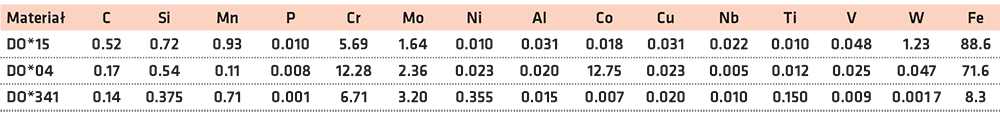
Test results specified the content of the main alloy additives. In the case of DO*341 wire, an increased content of Cr, Mo, V. and Ti was present; in the case of DO*04, a substantial measure of Cr, Co, and Mo; in the case of DO*15, a relatively large addition of Cr was confirmed, as well as Mo and W. A high chromium content was found in material DO*04. This classifies this alloy into stainless steels group (> 10.5%). Assuming that it has the characteristics of such material, passivation may occur on the surface (chromium oxides formation). This makes nitriding rather difficult or even impossible by stopping the diffusion of nitrogen atoms. Studies have shown, however, that the layer was formed, but it was of a smaller thickness and heterogeneous. To create hybrid layers formed by nitriding and surfacing, a nitriding technology was devised. For the purpose of nitriding, samples of 1 inch and a height of 10 mm (Figure 2c) were cut from welded ankle-shaped samples. Cube shape is adequate for later analysis of wear resistance. To compare the responsiveness to nitrogen diffusion, the welded samples were nitrided in a gas nitriding process with low potential to obtain a diffusion sphere without a layer of nitride on the surface. The process was performed with a nitriding potential Np = 0.25–0.40 atm-1/2 for approximately 10-13 hours.
3.3 Results of a microstructure analysis after pad welding
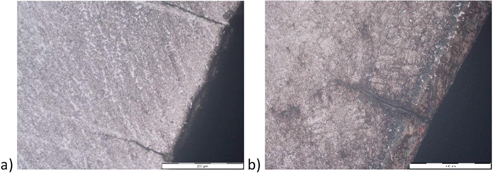
Microstructure underwent scrutiny for multiple reasons. The quality of the padding welds and their responsiveness to nitriding were evaluated. Reaction of their microstructure to nitriding as a chemo-thermal treatment was also analyzed. Samples designed for testing the microstructure of padding welds were prepared by cutting, grinding, and polishing as well as etching with the following reagents: Nital 5%, Picral 2%, and Villel reagent. The structure was analyzed throughout the entire sample cross section, paying attention to the microstructure of individual layers and transition zones. In Figure 3, pictures of microstructure of padding welds for three materials tested are shown.
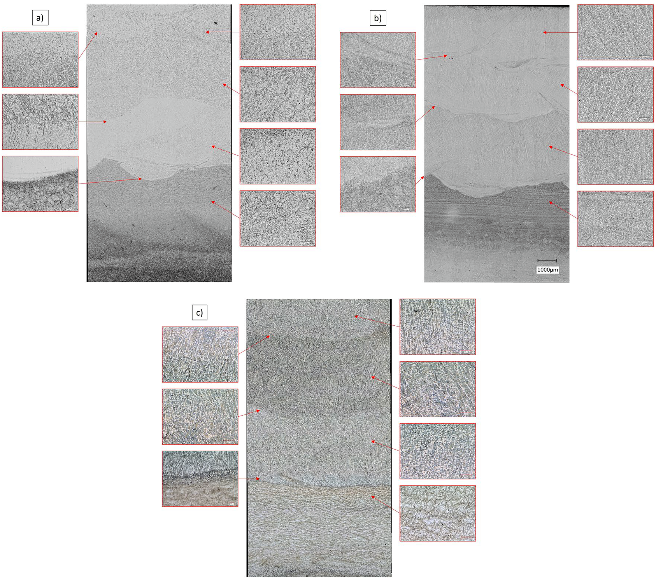
Padding welds have columnar grains perpendicular to the melting line with a dendritic formation. In their upper layer, the structure consists of fine-grained martensite with a substantial amount of austenite in the spaces between dendritics and a limited amount of fine carbides. The line of melting between layers, in all padding welds, had no welding incompatibilities, while areas where individual layers materials mix, are visible. Examination of the hybrid layer microstructure, combining surfacing and nitriding, was also carried out. Its aim was to assess the susceptibility of the padding welds to nitriding, evaluate the quality of the layers obtained, and the impact of the nitriding process on changes in the infused layers.
These studies showed varying but acceptable responsiveness of nitriding layers. Furthermore, they verified the beneficial effect of thermal treatment accompanying nitriding on the microstructure of the padding welds. They also revealed the type and amount of microstructure components present. Examples of microstructure of nitrided layers in hardfaced layers are shown in Figure 4.
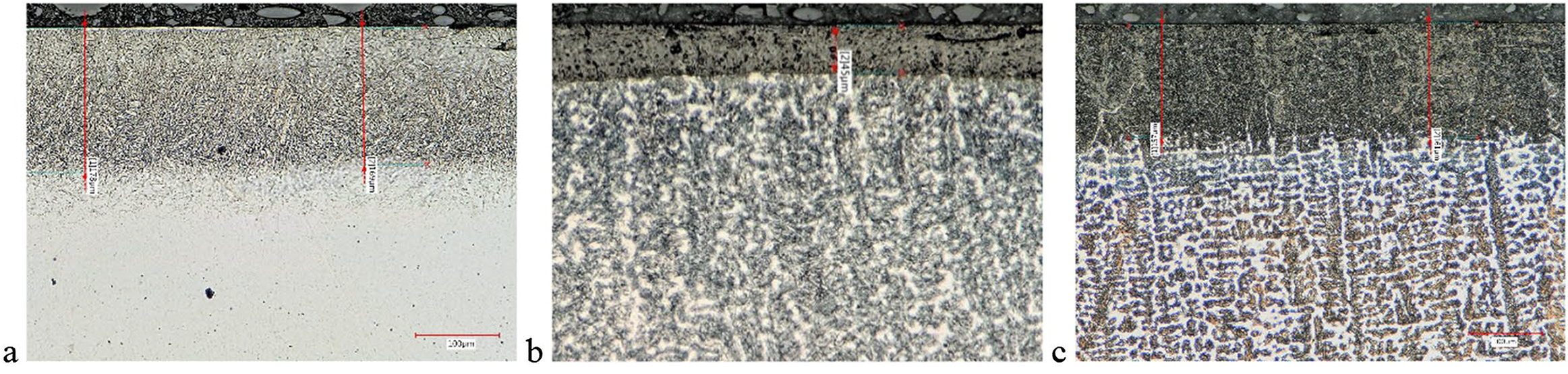
Figure 4a illustrates the microstructure of the nitrided layer on the surface of the three-layered padding weld from the DO*15 deposited on the substrate of H11 steel. This layer is about 178 µm thick. It consists of two areas. The outer lighter layer made of ε and ε + γ’ carbide nitrides with a thickness of approximately 20 µm passes into a darker layer of carbide nitrides of alloy elements. Only an insubstantial amount of nitride releases occurs on the surface of the nitrided layer. There is no γ’ phase separation grid in the nitrided layer formation that affects the layer’s fragility. As seen in Figure 4b, the nitrided layer on the surface of the DO*04 material is much thinner, approximately 45 µm thick. It is caused by the limited susceptibility to nitrogen diffusion in steels, which are similar in composition to the stainless steels (Chromium content above 10.5%). In these steels, material passivation (formation of chromium oxides) can occur, making nitriding significantly difficult or even impossible by blocking the diffusion of nitrogen atoms. It also affects the heterogeneous thickness of the layer, as Figure 4b shows. In Figure 4c, the microstructure of the nitrided layer on the surface of the three-layered padding weld from the DO*341 binder made on the gat steel is presented. WCL after thermochemical treatment nitriding. After digestion of the sample, a nitrided layer about 161 µm thick was revealed. The content of individual components of the microstructure was confirmed by the chemical composition XRF made for nitrides in the upper layer, the results of which are included in the chapter: phase composition test by the XRF method for nitrides in the upper layer.
3.4 Micro-hardness measurement results with description
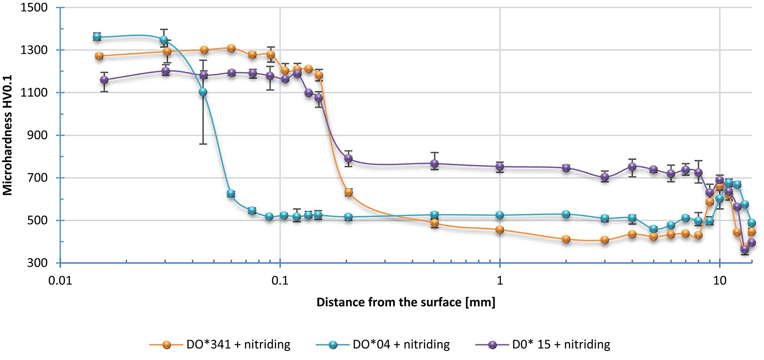
Micro-hardness tests were carried out for hardfaced layers (Figure 5) and for layers nitrided after hardfacing (Figure 6).
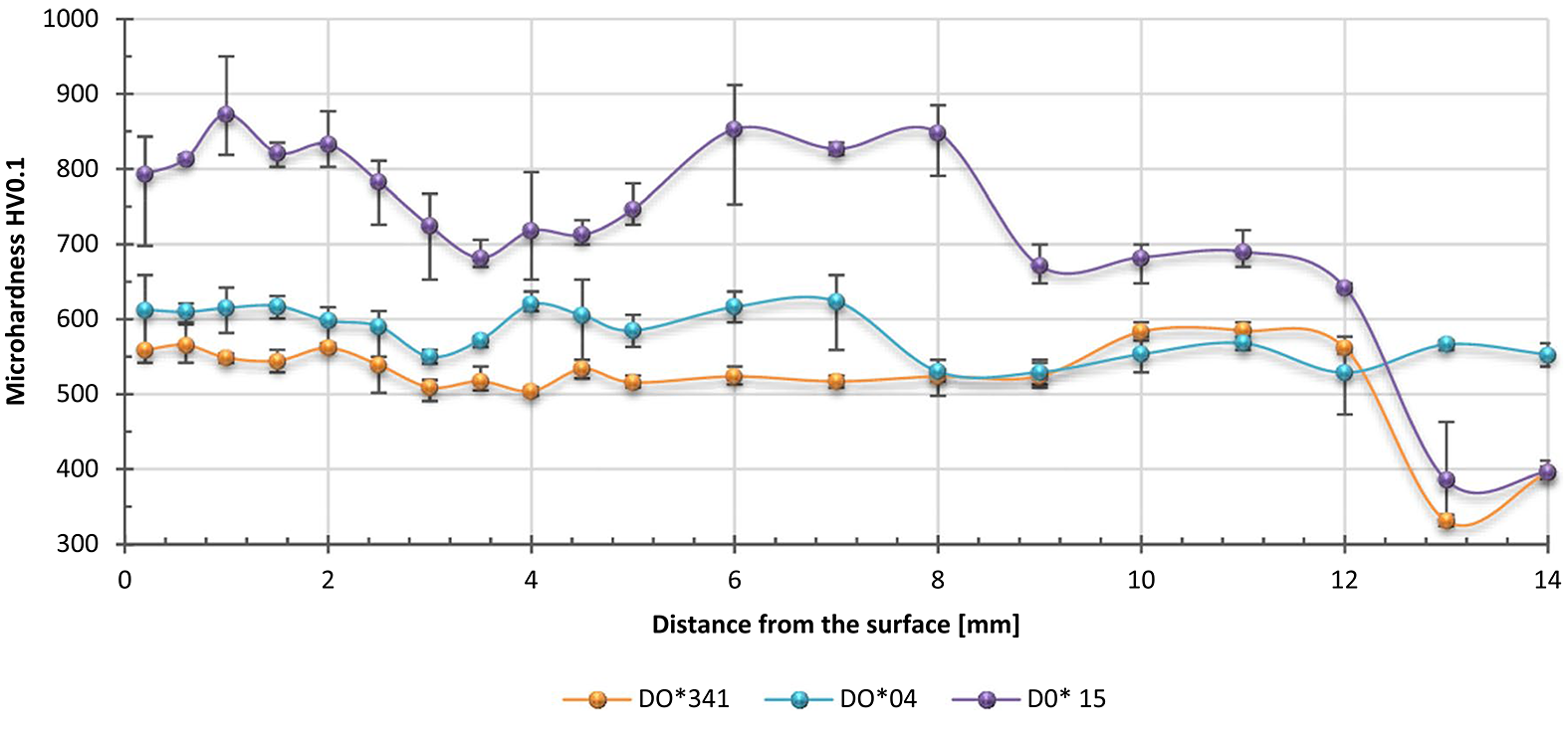
The results of the micro-hardness analysis revealed the variable hardness of the padding welds consisting of three layers. At depths below 12 mm, in the heat impact area for materials DO*341 and DO*15, the hardness has fallen below 400 HV. However, this does not affect the performance properties, because the distance from the surface is considerable. Hardness in individual layers was also measured, which in the case of DO*15 material is significantly dissimilar, which suggests the need for heat treatment by annealing.
The results confirmed obtaining an efficient thickness of the nitrided layers according to the HV + 50 criterion at the level of approximately 0.11 mm for materials and DO*341 and approximately 0.05 mm for material DO*04. Moreover, nitriding had a positive impact on the homogeneity of the material, because the hardness in the padding welds equalized at the level of approximately 425 HV for material DO*341, approximately 525 HV for material DO*04 and approximately 750 HV for DO*15 material. This confirms the benefits of nitriding the padding welds both in the surface layer and in the entire area of a padding weld. It can be assumed nitriding can replace heat treatment of the surfaced samples. On the other hand, in the heat affected zone (HAZ), annealing during nitriding did not affect the hardness of the material.
3.5 Abrasive wear test results at both room and higher temperature
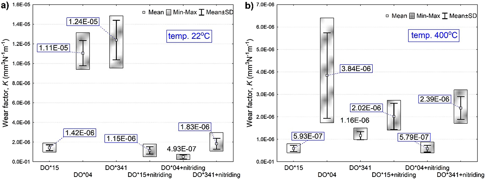
To estimate the abrasion resistance of the separate surfacing layers, as well as the effect of nitriding on the alternation in their resistance, a test was carried out under technically dry friction conditions at room temperature 22°C, and at a higher temperature of approximately 400°C. Balls with a diameter of 6 mm made of tungsten carbide were used as counter-samples. The tests were performed under a 10N load at a linear speed of 10 cm/s on a 3 mm radius. The entire route was 250 m. The K wear factor was determined as a comparative measure of wear that would consider the load and distance used during the test. An evaluation of the friction coefficient confirmed the stabilization of parameters in the ball-on-disc sample, which justifies the acceptance of the test results (Figure 7).
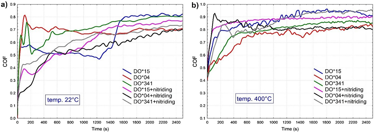
In Figure 8, friction coefficient curves (COF) are shown during the wear test, and in Figure 8, the average values of this coefficient are presented.
Evaluation of the friction coefficient confirmed the stabilization of parameters in the ball-on-disc sample, which justifies the acceptance of the test results.
The results obtained at 22°C temperature indicated a beneficial effect of nitriding on wear resistance for all the analyzed materials. Results of tests carried out at 400°C proved unsatisfactory, because they did not show any major improvement in durability, only for DO*04 material. It can be assumed the friction path was too short, and, therefore, there were only slight differences in the depth and cross-sectional area of the wear paths. To verify this hypothesis, observations of the wear path were made under the scanning microscope.
3.6 Analysis of wear mechanisms under the scanning microscope
To determine the cause of wear, many observations of wear paths were made. Destructive phenomena present on the surface of the tested samples were identified. Samples tested at 22°C (Figure 9a, 9b) have numerous parallel grooves, arranged in the direction of the ball feed on the disc. These are traces of abrasive wear that have increased due to microcracks. The effect of nitriding is visible in tensile materials, such as DO*04 and DO*341. On these materials, in place of extensive deformations, evenly arranged abrasive furrows appear, probably caused by hard nitrides crushed by a parallel working spalling mechanism. Successively, for DO*15 material, the non-nitrided sample and the nitrided probe show similar deterioration mechanisms. This is because the welded sample has a high hardness reaching 800HV, which allows to achieve high-wear resistance even without nitriding. For this reason, in the abrasive wear test (Figure 8) no significant differences between these samples were detected.
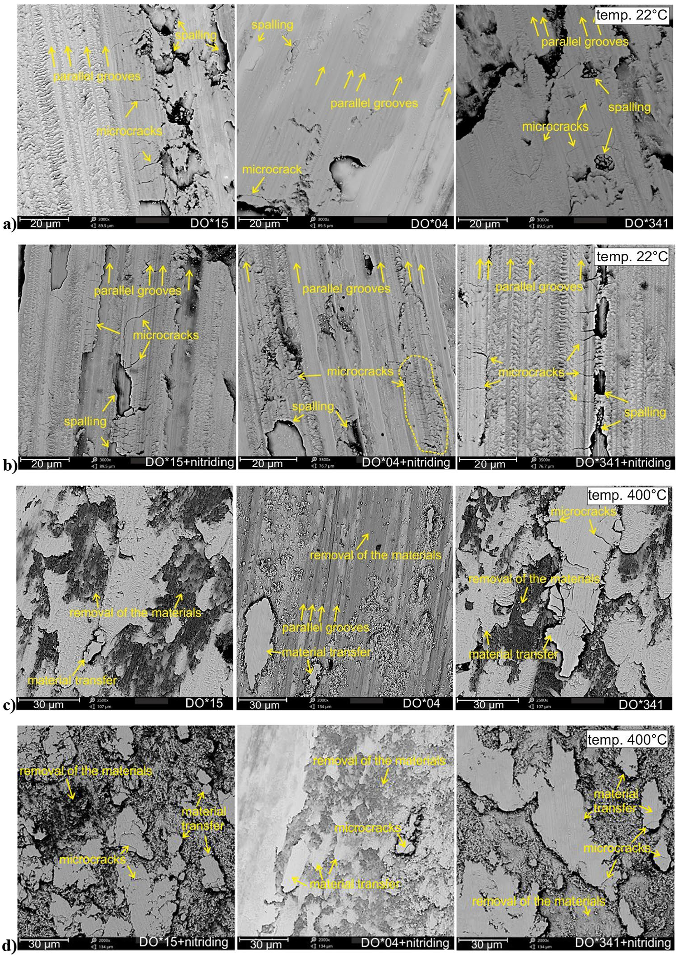
In the case of a test carried out at 400°C (Figure 9c, 9d) areas where the material has been damaged and removed from the sample surface can be observed. Deficiencies in the material show that, at higher temperature, plasticization occurs, and the mechanism of plastic deformation prevails, resulting in the removal of material fragments during abrasion. It is rather apparent that nitriding does not effectively stop wear under these conditions. At elevated temperatures, samples with nitrided layers (Figure 9d) have many microcracks on the surface. This is due to hardening of the layer, which modifies the impact of individual mechanisms, and wear and thermo-mechanical cracks can be more dangerous than abrasion. At an early stage of the ball-on-disc test, it can only be assumed that a more intense or long-lasting load will change the impact of individual mechanisms, as this is not yet detected.
3.7 Examination of phase composition for nitrides in the top layer, using the XRF method
To evaluate what influence nitriding has on wear, phase composition tests were performed that verified the occurrence of specific types of nitrides in the top layer. These tests were performed by X-ray diffraction. Figures 10a, 10b, and 10c show the results of diffraction measurements for the samples DO*15 + nitriding, DO*04 + nitriding, and DO*341 + nitriding, together with the standard Crystallography Open Database (COD) peaks of iron and iron nitrides. Detailed data on peaks positions, interplanar distances, half-widths, and the corresponding Miller indices are summarized in Table 4. The presented profiles for the samples DO*15 + nitriding and DO*341 + nitriding have the same set of X-ray diffraction peaks, differing in relative intensities and slight position shifts. On the other hand, the sample DO*04 + nitriding has a set of peaks that differs significantly from the other ones. Phase analysis was performed with HighScore Plus v. 3.0e using Crystallography Open Database. As a result of the analysis, it was found that for the sample DO*04 + nitriding, the peaks positions correspond to Fe with cubic structure (BCC) and the space group Im-3 m. On the other hand, the positions of the peaks in the X-ray diffraction profiles of the samples DO*15 + nitriding and DO*341 + nitriding correspond to the peaks of the following nitrides: Fe3N and Fe4N. Fe3N has a hexagonal structure and the space group P312 (Card No.: COD 96-101-1218), and Fe4N has a cubic structure with the space group P-43 m (Card No.: COD: 96-900-4226). The differences in the relative peak heights indicate different proportions of the individual nitrides. The performed Rietveld analysis allowed to determine the proportion of the amount of individual nitrides. For the DO*15 + nitriding sample, it was calculated that 23% was Fe4N and 77% Fe3N. However, for the sample DO*341 + nitriding, it is 18% Fe4N and 82% Fe3N.
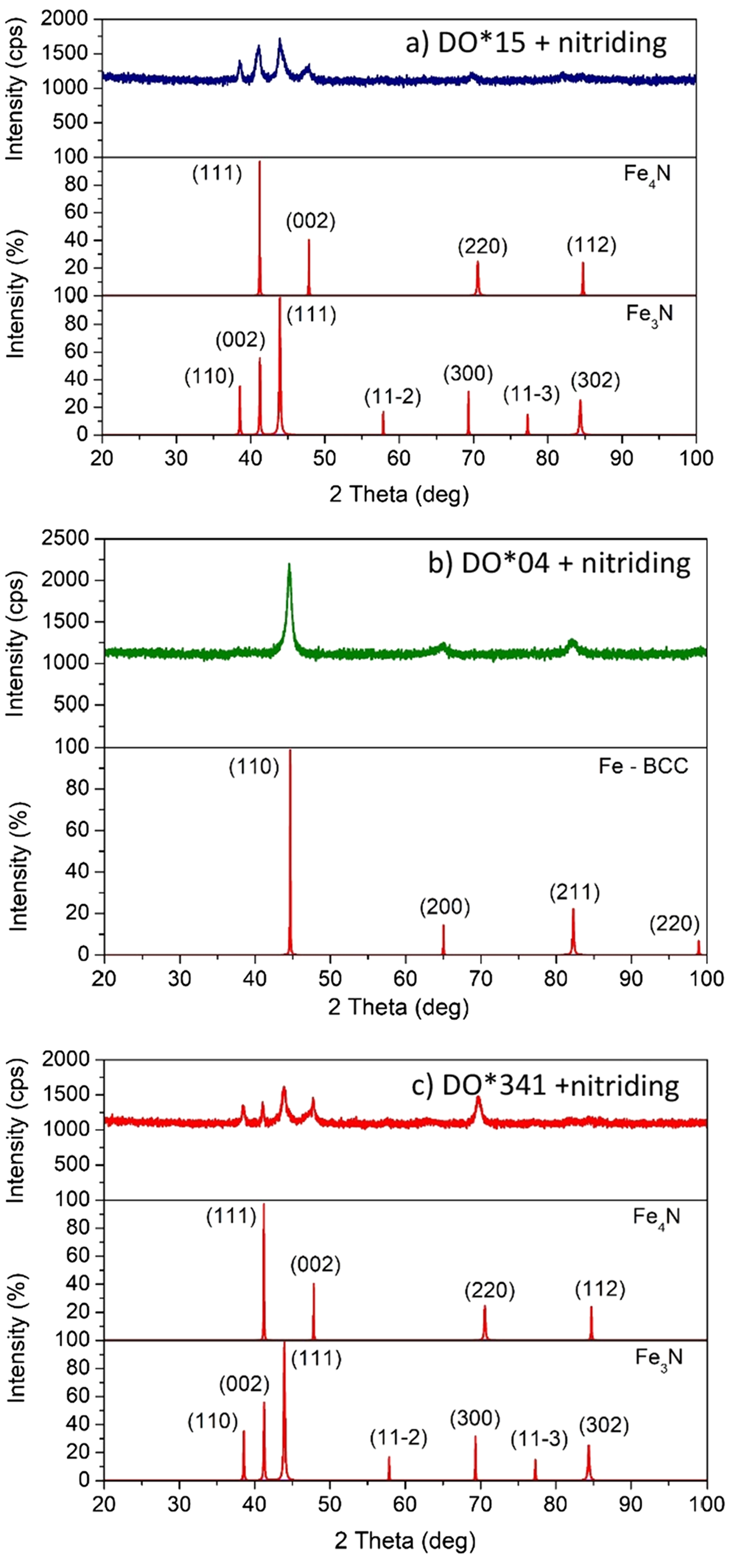
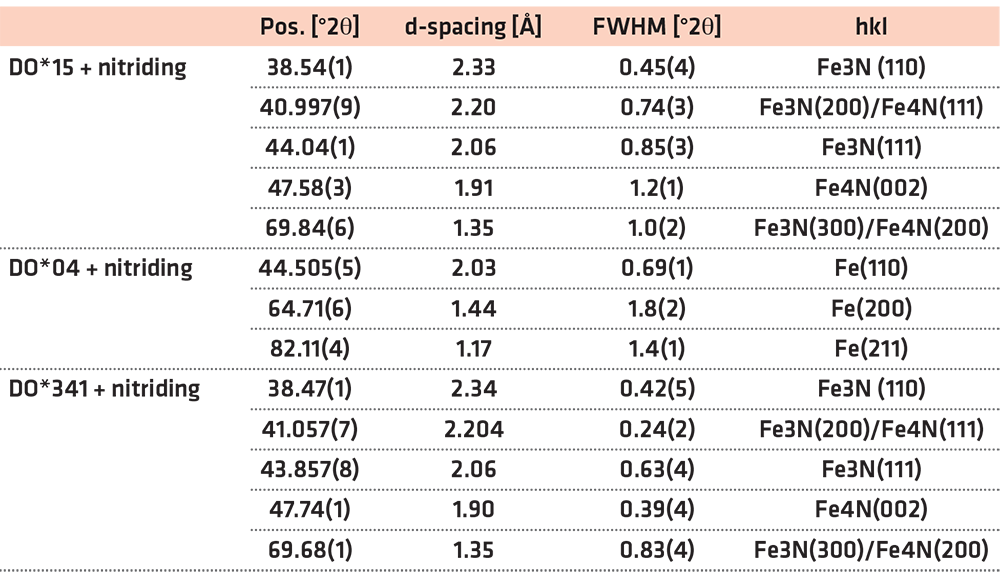
Results of the analysis presented in Figure 10 and in Table 4 point out that Fe3N or Fe4N nitrides was not detected on the surface of the DO*04 + nitride layer. Therefore, it may be concluded that, due to the passivation of the substance (formation of chromium oxides), nitriding was notably impeded by blocking the diffusion of nitrogen atoms. No nitrides were formed on the surface. This certainly affects wear significantly, especially when the testing of ball-on-disc at 22°C (Figure 8a) is remarkably lower comparing to other materials.
For the DO*15 + nitriding and DO*341 + nitriding layers, in which Fe3N and Fe4N nitrides are present, the negative effect of nitride surface formation can be noticed. This may promote cracking and thus intensify abrasive wear. Since in the DO*15 + nitriding layer there were 23% Fe4N and 77% Fe3N, it may postulated that a relatively higher content of γ’ nitrides’–Fe4N results from the chemical composition of the padding weld, which contains more carb-forming elements, such as chromium, molybdenum, and vanadium. In most case, the amount of nitrides on the surface was minimized due to proper nitriding processes; hence, it is difficult to assess their impact, since they were in small quantities.
3.8 Operational test results
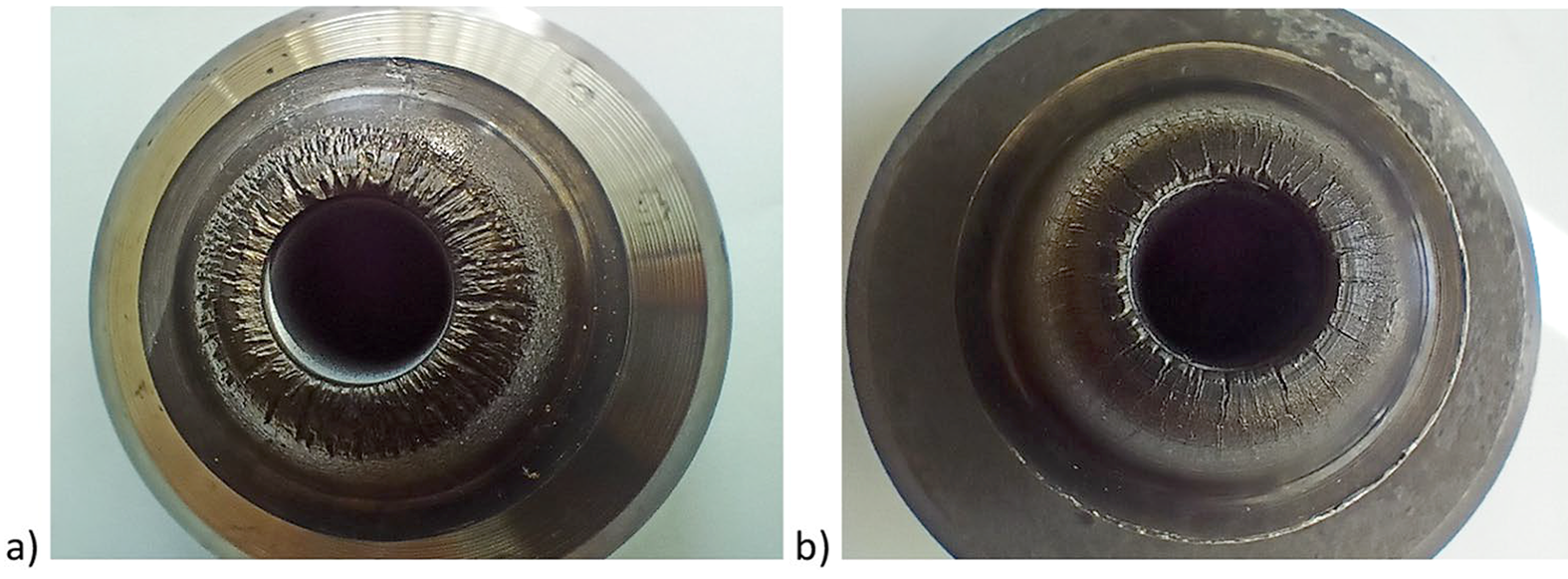
As described in the Materials and Methods section, operational tests in industrial conditions of tools with applied hybrid layers were carried out for a selected forging tool (Figure 1). The tests were carried out on two punches, which were hard-faced with different materials: DO*04, Fe–Cr–C–Mo and DO*15, Fe–Cr–Mo–W. Both punches were nitrided after hardfacing and machining. During the tests with the use of the analyzed tools, 5,337 forgings were forged, respectively, for the punch welded with the DO*04 material and 5,500 forgings for the punch welded with the DO*15 material.
First, the tools after operational tests were subjected to macroscopic analysis (Figure 11). In both cases, the observed traces of wear occur mainly on the front surface, grooves are formed there and occur in the radial direction, which is typical for abrasive wear. On the other hand, a grid of thermo-mechanical cracks is visible on the conical surface. Based on the observations, it can be concluded that on the tool clad with the DO*15 material, Fe–Cr–Mo–W cracks are clearly smaller and more even. On the front surface, there are visible furrows characteristic of abrasive wear, forming in the radial direction.
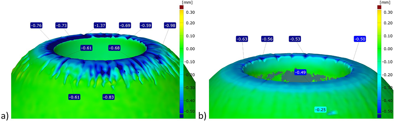
Then, the wear depth of the working patterns was measured. This wear was determined using the ATOS optical scanner. The analyzed tools were scanned before and after work, then the obtained scans were compared. This made it possible to precisely determine the depth of wear as a distance between scanned surfaces in individual areas, Figure 12).
The analysis of changes in the surface layer was also carried out using microscopic techniques, both using an optical microscope and observing the working surfaces of the tools using a scanning electron microscope. Selected results of the analysis of the destructive mechanisms of tools after the forging process are presented in Figures 13 and 14.
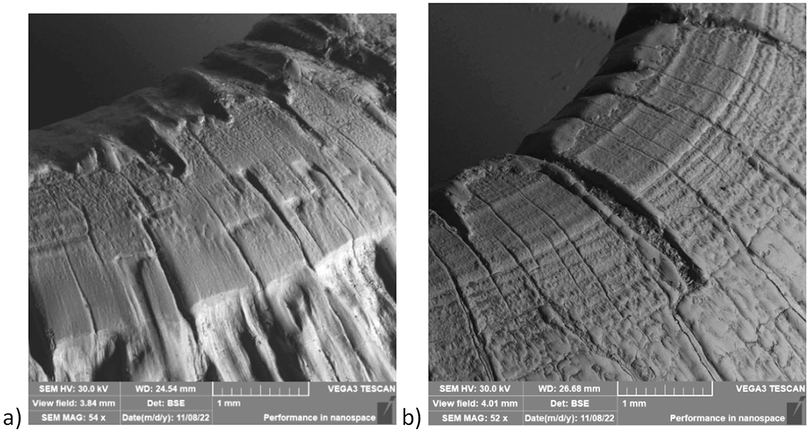
Microscopic observations revealed the main cause of wear of tools with applied hybrid layers is thermo-mechanical fatigue, which leads to the formation of a network of cracks in the surface layer. The cracks visible in Figure 14 have a depth of approx. 200-300 µ m. They are then deepened and widened, as a result of which abrasive grooves are formed along the direction of material flow on the surface.
Although the wear mechanism is undesirable and occurred in both cases of the analyzed tools, it should be noted it occurs with much lower intensity in the case of the tool clad with DO*15, Fe–Cr–Mo–W material. This was also clearly confirmed by the measurements of the wear depth presented in Figure 12, where with a similar number of forged forgings, the maximum wear for this tool is 0.63 mm compared to the maximum wear of the tool clad with DO*04 material, Fe–Cr–Co–Mo on 1.37 mm level.
4 Conclusions
1. It may be concluded that nitriding strengthens wear resistance of layers, which was observed for all three materials at 22°C. At temperature 400°C, it is rather problematic to assess what impact nitriding has on quantitative deterioration measured by the wear factor, nevertheless, changes in wear can be detected. At room temperature, mainly abrasive furrows are observed and at higher temperature to 400°C, thermo-mechanical cracks, not observed during operation at room temperature, are significant.
2. Nitriding as a thermo-chemical working is beneficial for the microstructure and properties of padding welds. It may replace the annealing or intense tempering of a material, which for steels designated for high-temperature operations, evokes the effect of a derivative hardness. The combination of surfacing with nitriding is also useful because of the relaxation of post-welding stresses occurring in the nitriding as an additional heat treatment.
3. Elements, such as chromium and cobalt, present in the DO*04 material prevent the diffusion of nitrogen from penetrating into the padding welds in alloy steels; nitriding process parameters should be changed accordingly. Due to difficulties with nitrogen diffusion, the nitrided layer was shallow and of uneven thickness. However, the favorable result was the lack of a nitride coating on the surface of the padding weld.
4. The DO*341 + nitriding material layer showed low wear resistance comparing to the non-nitrogen sample, which is associated with the presence of γ’-Fe4N (approximately nitrides 23%) and ε-Fe3N (approximately 77%) in the surface area and on the surface of the sample. Another factor was the low hardness of the padding weld material (approximately 500 HV0.1). This material is intended for use on forging dies on hammers, which means it must not be too hard to avoid brittle cracking in the impact loads.
5. Layers that come from DO*04 + nitriding and DO*15 + nitriding materials may be an adequate solution to the problem of excessive wear of the forging tools. They develop a significantly higher wear resistance comparing to the material of the padding welds at room temperature, in abrasive tests. They also show satisfactory wear resistance at 400°C temperature.
6. The effect of improving forging tool durability using hardfaced and nitrided layers was verified in an industrial hot forging process. The DO*15 + nitriding layer showed significantly higher resistance to abrasive wear, which was confirmed by the measurements of the wear depth, where with a similar number of forged forgings, the maximum wear for this tool is 0.63 mm compared to the maximum wear of the tool with DO*04 + nitriding layer on 1.37 mm level.
7. Observations revealed the main cause of wear of tools with applied hybrid layers is thermo-mechanical fatigue, which leads to the formation of a network of cracks in the surface layer. The cracks have a depth of approximately 200-300 µm. They are then deepened and widened, as a result of which abrasive grooves are formed along the direction of material flow on the surface. Although the wear mechanism is undesirable and occurred in both cases of the analyzed tools, it should be noted it occurs with much lower intensity in the case of the tool with DO*15 + nitriding layer.
Conflict of interest
All authors declare that he/she has no conflict of interest.
Ethical approval
This article does not contain any studies with animals performed by any of the authors. This article does not contain any studies with human participants or animals performed by any of the authors.
Additional information
Springer Nature remains neutral with regard to jurisdictional claims in published maps and institutional affiliations.
Acknowledgements
This study was funded by National Center for Research and Development, Poland (grant no. Lider X/0028/L-10/2018).
References
- Altan T, Ngaile G. Cold and Hot Forging : Fundamentals and Applications. 2005.
- Archard JF. Wear {Theory} and {Mechanisms}, Wear {Control} {Handbook}. 1980; https://doi.org/10.1016/0301-679X(81)90122-5.
- Gronostajski Z, Kaszuba M, Hawryluk M, Zwierzchowski M. A review of the degradation mechanisms of the hot forging tools, Archives of Civil and Mechanical. Engineering. 2014;14:528–39. https://doi.org/10.1016/j.acme.2014.07.002.
- Widomski P, Gronostajski Z. Comprehensive review of methods for increasing the durability of hot forging tools. Procedia Manuf. 2020;47:349–55. https://doi.org/10.1016/j.promfg.2020.04.280.
- Gronostajski Z, Widomski P, Kaszuba M, Zwierzchowski M, Polak S, Piechowicz Ł, Kowalska J, Długozima M. Influence of the phase structure of nitrides and properties of nitrided layers on the durability of tools applied in hot forging processes. J Manuf Process. 2020;52:247–62. https://doi.org/10.1016/j.jmapro.2020.01.037.
- Behrens BA, Yilkiran T, Ocylok S, Weisheit A, Kelbassa I. Deposition welding of hot forging dies using nanoparticle reinforced weld metal. Prod Eng Res Devel. 2014. https://doi.org/10.1007/s11740-014-0562-y.
- Bayramoglu M, Polat H, Geren N. Cost and performance evaluation of different surface treated dies for hot forging process. J Mater Process Technol. 2008. https://doi.org/10.1016/j.jmatprotec.2007.11.256.
- Weixin Z, Dejun K. Microstructure, tribological performances, and wear mechanisms of laser-cladded TiC-reinforced NiMo coatings under grease-lubrication condition. Mater Sci-Pol. 2021;39:395–409. https://doi.org/10.2478/msp-2021-0032.
- Górnik M, Jonda E, Łatka L, Nowakowska M, Godzierz M. Influence of spray distance on mechanical and tribological properties of HVOF sprayed WC-Co-Cr coatings. Mater Sci-Pol. 2021;39:545–54. https://doi.org/10.2478/msp-2021-0047.
- Nowakowska M, Sokołowski P, Tesař T, Mušálek R, Kiełczawa T. Al2 O3 -TiO2 coatings deposition by intermixed and double injection SPS concepts. Mater Sci-Pol. 2021;39:599–614. https://doi.org/10.2478/msp-2021-0046.
- Marques AS, de Costa LDL, dos Santos GR, da Silva Rocha A. Wear study of hot forging punches coated with WC-CoCr and Cr3C2-NiCr through high-velocity oxygen fuel (HVOF) process. Int J Adv Manuf Technol. 2019;100:3–11. https://doi.org/10.1007/s00170-018-2693-3.
- Gebauer M, Gustman T. Laser beam melting for added value in tooling applications, Chemnitz. 2019.
- Alphonsa J, Padsala BA, Chauhan BJ, Jhala G, Rayjada PA, Chauhan N, Soman SN, Raole PM. Plasma nitriding on welded joints of AISI 304 stainless steel. Surf Coat Technol. 2013. https://doi.org/10.1016/j.surfcoat.2012.05.113.
- Yokoyama H, Iio M. Engine Valve, JP 2012077998 W 20121030, EP 2915965 A1. 2015.
- Lukin VI, Kovalchuk VG, Golev YV, Mazalov IS, Ovchenkova II. Welding a creep-resisting Ni-Co-Cr (VZh171) alloy strengthened by nitriding. Weld Int. 2013. https://doi.org/10.1080/09507116.2013.796642.
- Gronostajski Z, Widomski P, Kaszuba M, Zwierzchowski M, Hawryluk M. Influence of both hardfaced and nitrided layers on the durability of hot forging tools. Surf Innov. 2018;6:301–10. https://doi.org/10.1680/jsuin.18.00021.
- Kaszuba M, Widomski P, Białucki P, Lange A, Boryczko B. Laboratory tests of properties of the new-generation hybrid layers combining hardfacing and nitriding dedicated for improvement of forging tools’ durability. Archiv Civ Mech Eng. 2020. https://doi.org/10.1007/s43452-020-00080-8.
- Widomski P, Gronostajski Z, Kaszuba M, Kowalska J, Pawełczyk M. The laboratory tests of hybrid layers combining hardfacing and nitriding dedicated to increase the durability of forging tools in hot forging processes. Weld Tech Rev. 2019;91:1–6. https://doi.org/10.26628/wtr.v91i2.1020.
- Kaszuba M. The application of a new, innovative, hybrid technology combining hardfacing and nitriding to increase the durability of forging tools. Archiv Civ Mech Eng. 2020;20:122. https://doi.org/10.1007/s43452-020-00122-1.
- Kopec M, Gorniewicz D, Kukla D, Barwinska I, Jóźwiak S, Sitek R, Kowalewski ZL. Effect of plasma nitriding process on the fatigue and high temperature corrosion resistance of Inconel 740H nickel alloy. Archiv Civ Mech Eng. 2022;22:57. https://doi.org/10.1007/s43452-022-00381-0.
- Frączek T, Michalski J, Kucharska B, Opydo M, Ogórek M. Phase transformations in the nitrided layer during annealing under reduced pressure. Archiv Civ Mech Eng. 2021;21:48. https://doi.org/10.1007/s43452-020-00158-3.
- Jabłońska MB, Jasiak K, Kowalczyk K, Skwarski M, Rodak K, Gronostajski Z. The influence of the heat generation during deformation on the mechanical properties and microstructure of the selected TWIP steels. IntJ Mater Form. 2023;16:30. https://doi.org/10.1007/s12289-023-01753-4.
- Jabłońska MB, Jasiak K, Kowalczyk K, Bednarczyk I, Skwarski M, Tkocz M, Gronostajski Z. Deformation behaviour of high-manganese steel with addition of niobium under quasi-static tensile loading. Mater Sci-Pol. 2022;40:1–11. https://doi.org/10.2478/msp-2022-0029.
About the authors
Paweł Widomski, Marcin Kaszuba, Paweł Sokołowski, and Artur Lange are with the Department of Metal Forming, Welding and Metrology, Faculty of Mechanical Engineering, Wroclaw University of Science and Technology. Mariusz Walczak is with the Department of Material Engineering, Lublin University of Technology. Marcin Długozima is with the R&D Department, SECO/WARWICK. Mateusz Gierek is with Castolin Eutectic. Dariusz Chocyk and Grzegorz Gładyszewski are with the Department of Applied Physics, Lublin University of Technology. Bożena Boryczko is with the Department of Metal Working and Physical Metallurgy of Non Ferrous Metals, AGH University of Science and Technology.
© 2023 by the authors. This article is an open access article (https://link.springer.com/article/10.1007/s43452-023-00778-5) distributed under the terms and conditions of the Creative Commons Attribution (CC BY) license (https://creativecommons.org/licenses/by/4.0/). It has been edited to conform to the style of Thermal Processing magazine.


 general practice for CQI-9 and AMS2750E")


