


In this column, I will review the basic requirements of agitation, and illustrate a method of determining the right amount of agitation.
Recently, a customer wanted to create a new quench tank for polymer quenchants. This tank was to quench long carburized shafting that had previously been quenched in oil. The customer’s goal was to reduce costs and reduce the smoke and fire hazard.
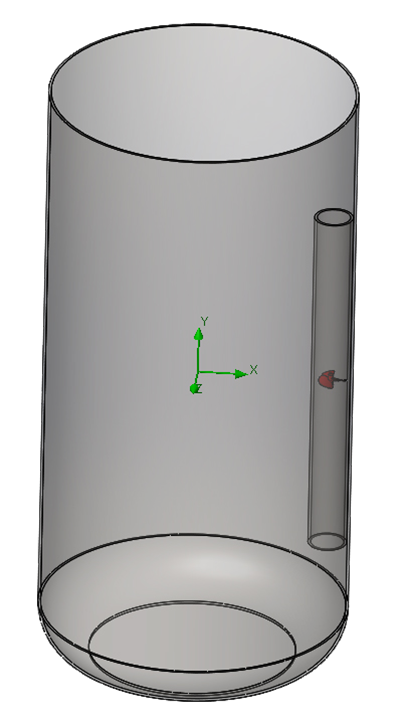
The quench tank was simple. It was a cylinder 3m (118 inches) in diameter, and 6m (236 inches) deep. There was a slight radius at the bottom of 500 mm (20 inches) to help direct flow. Agitation was provided by a single 3.75 KW (5 HP) 300 mm (12 inches) marine-type agitator in the middle of a 325 mm (13 inches) draft tube that was 3.5 meters (137.75 inches) long (Figure 1). The desired flow rate is upwards through the load, preferably at greater than 0.5 m/s (98.4 ft/min).
A simple model of the quench tank was created to examine the flow. Since the impeller has a twisting flow, it was not appropriate to look at the flow as in symmetry. While this increased computational time, the results would be improved.
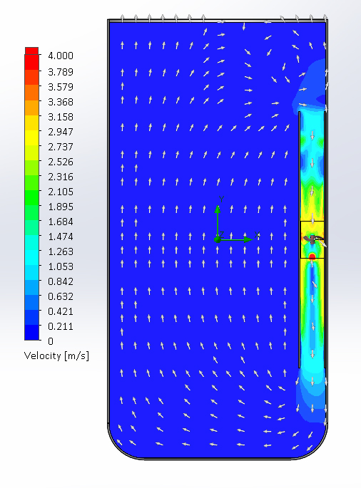
The resulting flow through the work zone was poor. While the flow was predominantly directed upward through the work zone, the upward velocity in the quench tank was very low, at 0.015 m/s (2.95 ft/min). This flow rate is entirely inadequate for quenching and is essentially a “dead” tank. Figure 2 shows the resultant flow pattern in the tank.
Additional agitation is needed to meet the desired flow rate of greater than 0.5 m/s.
Sizing Agitation
The first requirement is to determine the amount of quenchant that must be moved. The volume of a cylinder is:
 Where R is the radius of the tank (R = 1.5m) and L is the length (L = 6m). We will ignore the radius at the bottom of the tank for simplicity. From the above, the volume of the tank is 42.41 m3 (42,410 liters) or 11,200 gallons.
Much of the early work on impellers for quenching applications is based on the classic work by U.S. Steel [1]. This work was based on marine-type impellers. However, many improvements have been made to improve the flow and energy efficiency of impeller or propeller type agitators.
In this work, the power requirements for marine-type impellers were illustrated. However, improvements in impeller and motor design have enabled 40 percent greater flow efficiency with modaern airfoil-type impellers operating at lower speeds. The recommended power requirements for impeller agitation are shown in Table 1. These values should be considered as minimum power requirements [2].
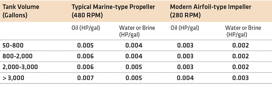
Using the values for modern airfoil-type impellers (0.003 HP/gal), a total power required is 33.6 HP.
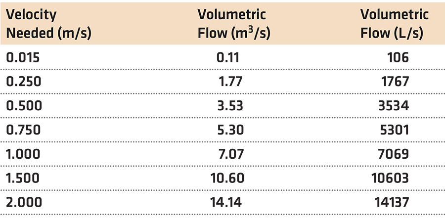
The volumetric flow required is velocity (v) * Area or
 This is shown in Table 2. Based on the desired minimum flow rate of 0.5 m/s, this would mean that a minimum volumetric flow rate of 3,534 L/s is required. Examining Figure 3, it shows that the existing 300 mm marine impeller only produces a volumetric flow rate of approximately 90 L/s. This explains the very low flow in the quench tank and matches closely with that calculated using CFD.
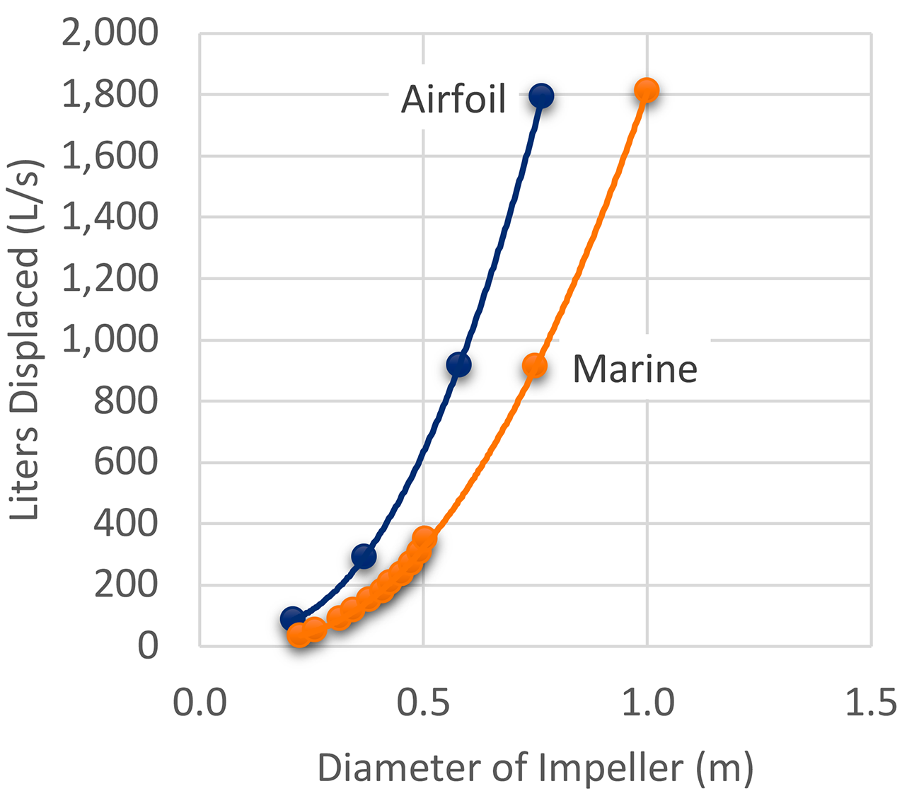
To achieve the desired flow rate of 0.5 m/s minimum, additional agitators are needed. Six 500 mm diameter airfoil agitators are needed, or eight 400 mm diameter airfoil agitators are required.
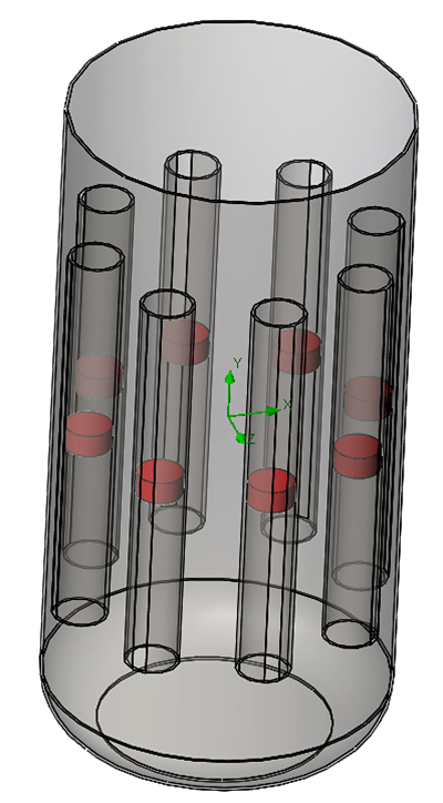
Taking the calculated number of agitators, a new model of the tank was created. In this case, eight 400 mm impellers were placed at 45° around the quench tank periphery (Figure 4). To reduce the computational load, disks were placed at the location of the impellers, with inlet/outlet flows of 400 kg/s (400 L/s) for a combined total of 3,200 L/s.
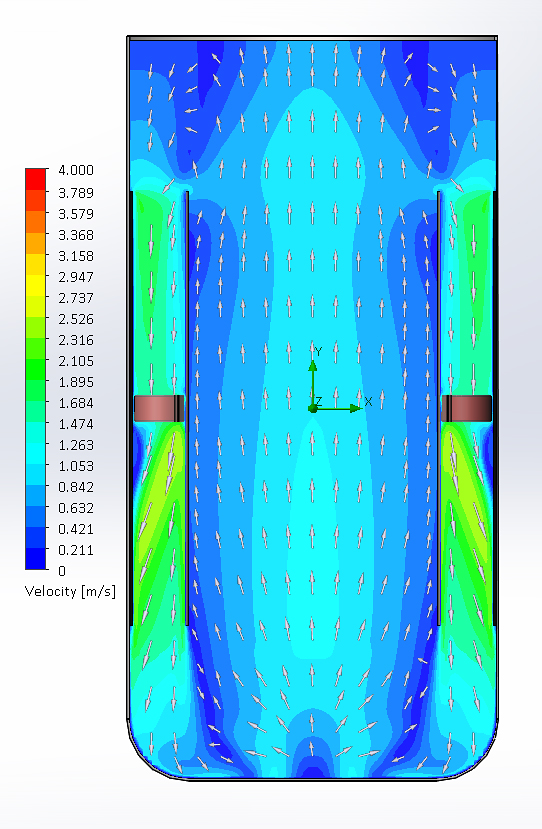
The results of the analysis (Figure 5) show that the flow in the center of the tank is approximately 1.0 m/s, while at the edges of the work zone is 0.5 m/s. The resultant flow is greater than expected and can be the result of the synergy of the flows coming together in the center to produce a higher velocity in the center of the tank. The flow appears to be uniform, and appropriate for quenching shafts. The overall flow meets the minimum flow requirement of 0.5 m/s.
Conclusions
In this column, a method has been demonstrated to calculate the amount and size of agitators needed for a quench tank. The method shown is conservative and will often produce higher agitation rates than are necessary. However, the flows can be reduced through proper motor controls, such as a frequency drive.
Should you have any questions on this article, or suggestions for new articles, please contact the editor or the writer.
References
- United States Steel, “Improved Quenching of Steel by Propeller Agitation,” United States Steel, Inc., Pittsburgh, PA, 1957.
- H. R. Bergmann, “Importance of Agitation for Optimum Quenching,” Met. Eng. Quarterly, vol. 2, no. May, pp. 17-19, 1971.
- G. E. Totten and K. S. Lally, “Proper Agitation Dictates Sucess – Part I,” Heat Treating, no. September, pp. 12-17, 1992.
- D. S. MacKenzie, “Quenchant Agitation, Design, and Characterization,” in Steel Heat Treating Technologies, J. L. Dossett and G. E. Totten, Eds., Materials Park, OH: ASM International, 2014, pp. 281-303.


 general practice for CQI-9 and AMS2750E")


