


Steel gears are heat treated to obtain enhanced properties and improved service performance. Quench hardening is one of the most important heat treatment processes used to increase the strength and hardness of steel parts. Defects seen in quenched parts are often due to high thermal and phase transformation stresses. Typical defects include excessive distortion, surface decarburization, quench cracks, large grain growth, and unfavorable residual stresses. Gear geometries with large section differences may suffer high stress concentrations and crack during quenching. Surface decarburization before quenching may lead to high surface residual tension and possible post heat treatment cracking. In this paper, the commercial heat treatment software DANTE is used to investigate three examples of heat treatment defects. Improved processes are suggested with the help of modeling. The first example is an oil quench process for a large gear. Peeling cracks were observed on the gear surface during grinding of the quench-hardened gears. Computer modeling showed that surface decarburization was the cause. The second example is a press quench of a large face gear. Unexpected large axial bow distortion was observed in quenched gears, and computer modeling indicated that an incorrect press load and die setup were the reasons. The third example is an in-process quenching crack caused by high concentrated tensile stress from unbalanced temperature and phase transformations in a spiral bevel pinion gear. The quenching process was modified to solve the problem. This example also emphasizes the need for heat treatment modeling in gear design to reduce the possibility of heat treatment defects. The three examples illustrate how to effectively use heat treatment modeling to improve the quality of the gear products.
Introduction
During heat treatment of steel gears, thermal gradient, phase transformation, and the resultant internal stress interact with each other to contribute to distortion and residual stress in the quench-hardened parts. Both distortion and internal stress during quenching are complicated and not intuitively understandable in most cases, which make process troubleshooting and improvement difficult. To reduce the machining cost after heat treatment, minimum distortion is preferred. Minimum distortion can be obtained by tuning up the heat treatment process parameters, such as heating and cooling rates, and carburization schedules, etc., although such tune ups are usually costly and time consuming. The increasing demand of gear performance requires the designer to take advantage of the favorable resiudal stresses obtained from carburized and quenching processes. To achieve these goals, computer modeling is being more widely used in the heat treat industry to optimize the heat treatment process [1-3]. DANTE is a commercialized heat treatment software based on the finite element method [4]. It can be used to predict the phase transformations, deformation, residual stresses, hardness, and distortion for heating, carburization, cooling, and tempering processes.
Surface decarburization affects the surface hardness achieved by the quenching process. Many heat treaters believe that the decarburized layer can be ground off to regain higher surface hardness and the effect of decarburization is totally eliminated. Decarburization also affects the surface residual stresses [5]. Favorable residual compression is expected on the surface of steel parts from carburization and quenching processes. Decarburization can shift the surface stress from compression to tension, and the effect on the depth of tensile stress is normally deeper than the depth of the decarburized layer. A grinding process may not able to effectively remove the surface tension and regain favorable residual compression. Computer modeling can be used to understand the relationship between the depth of decarburized layer and its effect on residual stresses.
A press quench is often used to reduce the distortion of gears larger than eight inches in diameter. The press quench is more complicated than the traditional oil quench, and distortion can be affected significantly by the selection of the quench press, die geometry and quenchant channel design, and the process setup.
Excessive distortion and quench cracks are often seen in gears with large section differences. Nonuniform phase transformation between thin and thick sections can lead to stress concentration in a gear during the quenching process, and excessive stress can crack the part at the worst, or distort the part at the least. The quenching process can be modified to reduce the possibility of cracking or to control size and shape change.
Quenching is a highly nonlinear process due to phase transformations and plastic deformation. Effective computer modeling is required to understand the part response during quenching before solutions to problems can be obtained [6]. A gear can rarely be designed with perfectly uniform section, so knowledge of the effects of gear geometry on potential heat treatment defects is critical for the gear designer. Heat treatment models can be used in the gear design process to reduce cost, improve quality, as well as shorten the design cycle.
Effect of Decarburization on Residual Stresses
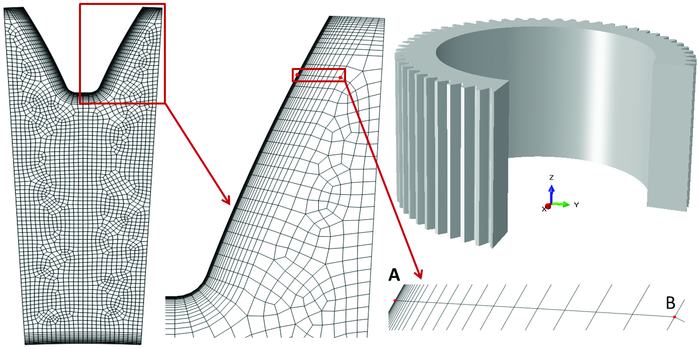
A ring gear made of AISI 4320 was carburized, quench hardened, tempered at a relatively low temperature, and then finished by a grinding process. Peeling cracks on the tooth face were observed during the grinding of the hardened gears. The axial height of the ring gear is 650mm, the inner diameter is 950mm, the tip diameter is 1300mm, the root diameter is 1210mm, and the gear has 60 outer straight teeth. Because of the gear geometry and the observed cracking mode, a plane strain FEA model of a single tooth with cyclic boundary conditions was created to investigate the causes of cracking. Figure 1 hows a CAD model of this ring gear and the finite element model created for heat treatment simulations. To model the decarburization effect, very fine elements are required in the shallow surface to ascertain the carbon, temperature, phase, and stress gradients during quenching. Point A in Figure 1 is located right on the tooth surface, and point B is located at a 6mm normal depth from the surface. The material response along the straight line AB is used to investigate the effect of decarburization. The gear face from tip to root cools at different rates during quenching. Contour plots of carbon, temperature, metallurgical phases, and stresses are used to understand the part response. Modeling results indicate that the grinding cracks are caused by high residual tensile stresses in the tooth surface due to decarburization.
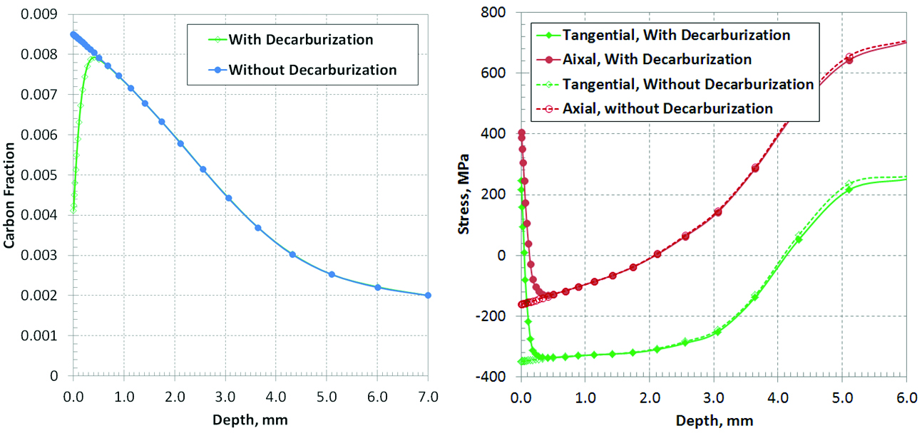
The carburization temperature was 950°C, and a boost/diffuse process was used to expedite the carbon diffusion rate. The boost step was 35 hours with a 1.0% carbon potential, and the diffuse step was 15 hours with a 0.85% carbon potential. At the end of the carburization process, the predicted carbon distribution is shown by the curve with solid markers in Figure 2(a). At high temperature when the gear is entirely austenite, its surface may decarburize in an atmosphere containing oxygen. An oxidizing atmosphere can be found in a poorly maintained furnace. During the transfer from furnace to quench tank, gears are exposed to air. For large parts, the transfer time in air is usually longer than for small parts, which makes the decarburization effect more significant due to the reaction time between the oxygen and surface carbon. The transfer time from furnace to the quench tank is 2 minutes. However, an oxygen atmosphere in the furnace can cause surface decarburization. In this study, it is assumed that the ring gear is exposed to an oxygen atmosphere for 10 minutes before being quenched, which is a combined effect of furnace atmosphere and air transfer. The surface carbon is assumed to drop to 0.4% due to the carbon-oxygen reaction. The carbon distribution within the decarburization zone is shown by the curve with hollow diamond markers in Figure 2(a). The depth of decarburized layer is about 0.10mm using 0.65%C as the initial threshold. Without decarburization, the predicted axial and tangential stresses after quenching are 160 MPa and 350 MPa in compression, respectively. With decarburization, the axial and tangential surface stresses are 400 MPa and 250MPa in tension. The change in axial residual surface stress due to decarburization is 560MPa. The tensile stresses will contribute to the cracking probability during the grinding process.
During quenching, both the thermal gradient and phase transformations contribute to the stress evolution in the part. Contours of carbon profile and martensite distribution after quenching are shown in Figure 3. The carburized case contains mainly martensite with about 10% retained austenite in the as-quenched condition. The retained austenite will transform to bainite during the tempering process. The depth of the hardened case increases from the root to tip along the tooth face due higher cooling toward the tooth tip and the deeper martensite distribution. The gear body microstructure is about 90% bainite and 10% martensite.
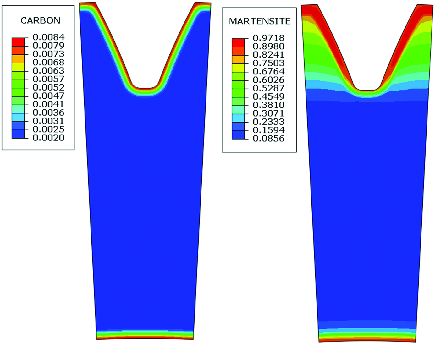
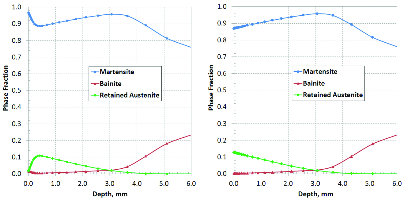
Figure 4 shows the phase distributions along line AB (Figure 1) at the end of the quenching process. With decarburization, 100% martensite is formed right on the surface because the martensite transformation finishing temperature (Mf) is higher than the room temperature for 0.4% carbon of this steel grade. Under the decarburized layer, the carbon content is about 0.8%, and 12% retained austenite is predicted to be present after quenching.
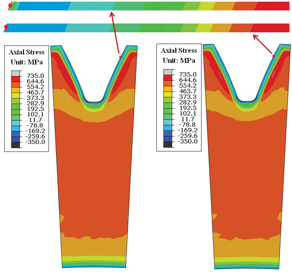
For steel, the starting temperature (Ms) for martensite transformation decreases as the carbon level increases. During a traditional oil quench process, martensite formation is delayed in the carburized case due to its high carbon content. There is a volume expansion with martensite formation. In a carburized gear, the surface transforms to martensite after the case-core location has formed martensite during a traditional oil quench. The delayed surface expansion leads to residual compression in the carburized case. If decarburization occurs before quenching, martensite formation starts in the shallow decarburized layer earlier than in the subsurface layers, and the delayed volume expansion of the sub-surface under the decarburized case will convert the stresses in the shallow decarburized case from compression to tension. Low temperature tempering does not have a significant effect on the residual stress distribution. Both axial and tangential residual stresses contribution to the cracking possibility during grinding, but axial stress usually dominates because of its higher magnitude. The contour plots of the axial residual stress are shown in Figure 5.
Distortion Analysis of Large Face Gear during Press Quench
Large gears are often quenched in a press in order to meet the dimensional requirements. The gear distortion can be significantly affected by the quench press equipment, the die design, the quenchant flow and the process sequence. In this section, a press quenching process for a large face gear about one meter in diameter is modeled using DANTE. The causes of distortion are examined, and an improved process is suggested.
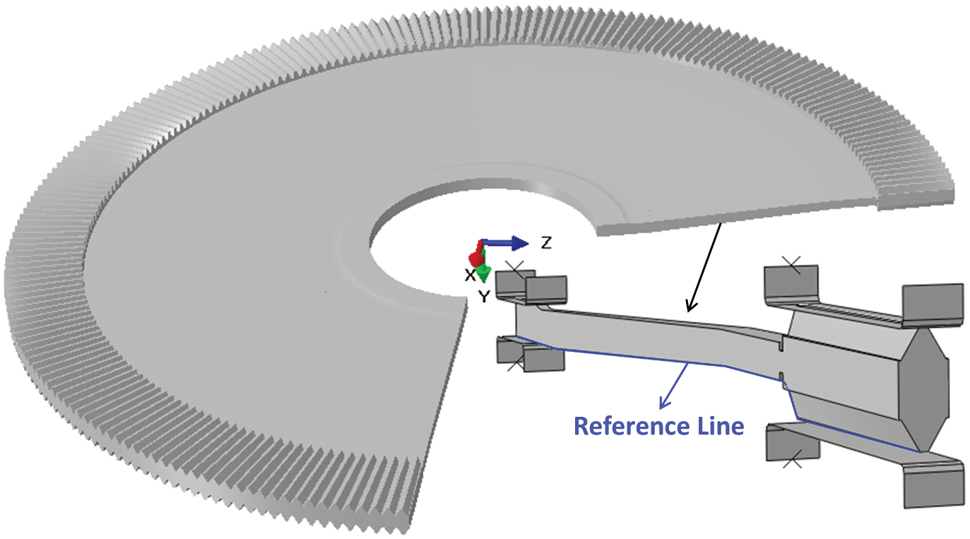
A simplified CAD model of the face gear is shown in Figure 6. The face gear has a large ratio of diameter to thickness. The web of this face gear is not planar, and it behaves like a washer inside the die during quenching. The main distortion mode is bow deflection in the axial direction, and a single tooth model with cyclic boundary conditions is effective for predicting this type of distortion. The quenching dies are assumed to be rigid in the model. The bottom dies are fixed during quenching. The same load is applied to the hub die and the tooth die. Both hub and tooth dies on the top can move freely in a vertical direction during the quenching process. Quench oil is assumed to flow over the part on the top and bottom surfaces in a general inward to outward direction. A friction coefficient of 0.15 is assumed between the dies and gear surfaces. The press quench model setup is shown in Figure 6. The reference line shown in Figure 6 is used to represent the gear shape during both heating and quenching processes.
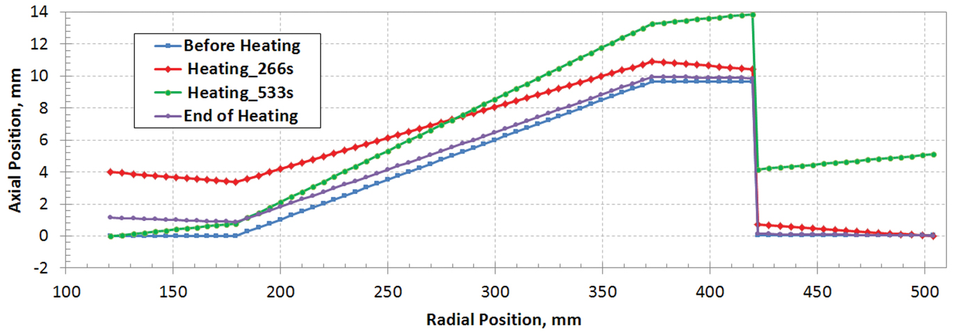
The gear tooth section is thicker than that of gear hub. During the heating process, the hub heats faster than the tooth section, and it will reach the furnace set temperature earlier. This means that the phase transformation to austenite starts and finishes earlier in the hub section. Material volume shrinks with transformation to austenite. The timing difference for volume shrinkage between gear tooth and hub creates internal stresses and axial displacement. Assuming that the gear sits on a support surface with the bottom surfaces of gear hub and tooth sections contacting the supporter, the shape change of the gear during heating is shown in Figure 7. The reference line in Figure 6 is used to represent the gear shape. At different furnace heating times, the model results show that it may have only hub or tooth section contacting the support. Significant axial bow deflection will occur during a free furnace heating process. However, the predicted axial deflection at the end of heating is only 1mm with the hub displaced upward.
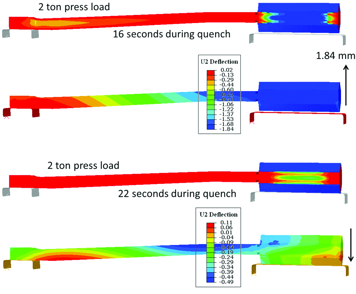
During the press quench, an excessive press load can cause distortion of the gear tooth due to TRIP effect, or may even damage the tooth profile by plastic deformation. In general, an applied load is used to hold the gear in the dies instead of totally constraining the gear using displacement control. A minimum load is preferred to effectively hold the gear in the dies. An insufficient load means that the reaction force from the gear exceeds the applied press load, as shown in Figure 8, and a section of the part may separate from the die. At 16 seconds during quenching, martensite formation in the hub and web is almost completed, so the gear web has high strength. A press load of two tons is insufficient to hold the gear at this point. The top die is pushed up about 1.84mm, and the gear tooth section is separated from the bottom die. With further martensite formation in the tooth section, the gear tooth moves down against the bottom die. A load of two tons is sufficient to hold the gear once the phase transformation is completed.
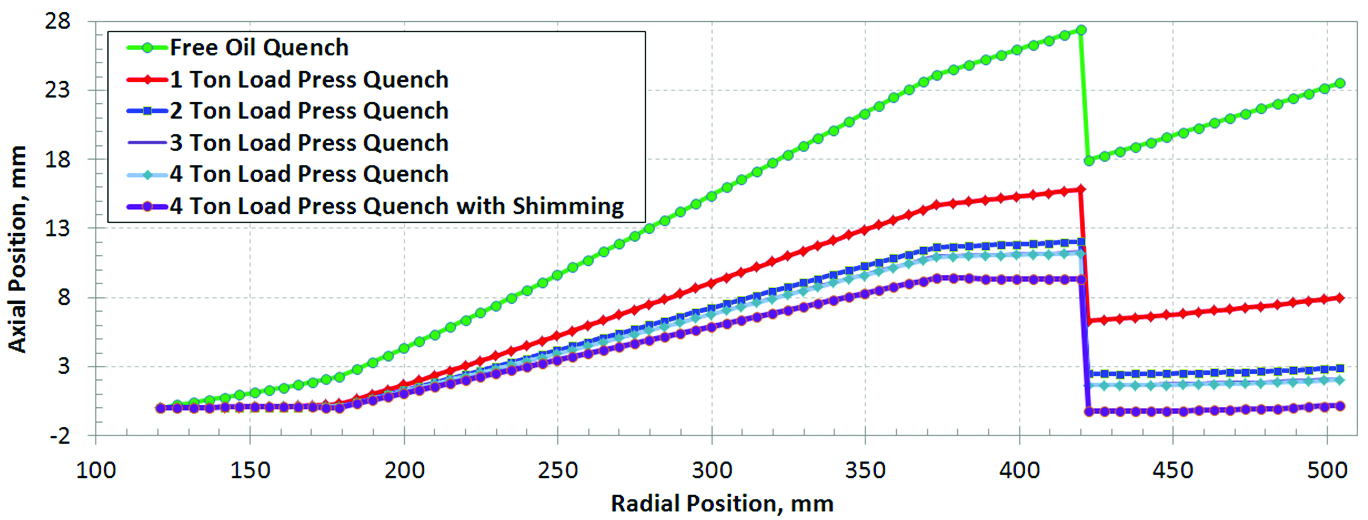
The effect of applied press load on axial bow distortion was investigated using finite element models by applying different loads during the press quench. A free oil quench process was modeled to compare with the press quench results. Due to the washer shape of this face gear, the distortion experienced in the free quench is extremely large. The predicted axial bow distortion is about 24mm upward at the tooth section, as shown in Figure 9. With a 1-ton press load, the predicted axial distortion is about 8mm. Increasing the load to 2 tons, the predicted distortion is reduced to 3mm. There is no noticeable difference on distortion between 3 and 4 tons load, and the distortion is about 2mm. A minimum of 3 tons load is required for press quench. A load of 4 tons has no negative effective on the gear tooth profile, and 4 tons load is suggested.
With sufficient press load (4 tons), the gear is hold inside the dies consistently during the entire press quench process. Due to the thermal gradients and phase transformations during quenching, residual stresses exist in the gear at the end of press quench. A 2.0mm springback is predicted after removing the press load, and the spring back is basically the
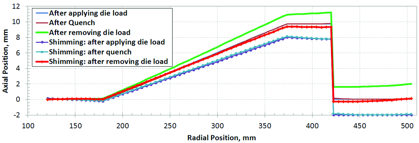
final distortion amount, as shown in Figure 10. By applying a 2.0mm shim to raise the hub section in the initial die setup, the axial bow distortion caused by the spring back can be compensated. With the shimming, the gear is deformed with the tooth section moving downward 2.0mm after closing the die and applying the press load. There is no significant difference of residual stresses between the cases with and without shimming, and both cases have a similar spring back amount, meaning the shim is predicted to accomplish the desired improvement in final dimensions.
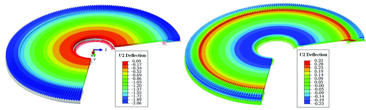
Small amount of distortion exists in the press quenched gear with shimming. Figure 11 compares the axial bow deflections in the final part between the two cases with and without shimming. The distortion can be effectively controlled by applying the shim.
Quench Crack of Pinion Gear During Quenching Process
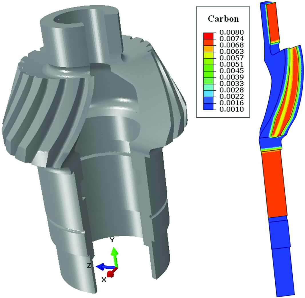
The intensive quenching process was used to improve the residual stress state of a pinion gear with spiral bevel teeth. The axial height of the gear is about 150mm, and the largest outer diameter of the tooth is about 100mm. The gear has 22 teeth as shown by the CAD model in Figure 12. The gear is made of AISI 9310. Only a portion of the gear surface is carburized, and the uncarburized surface is copper plated prior to carburization. The pinion gear has a high cracking possibility during intensive quenching process, especially if the process deviates from the designed process. Finite element models were used to understand the effects of process parameters on stress state and possible causes of cracking. Based on the modeling results, an improved intensive quenching process has been suggested to reduce the cracking possibility. A single tooth model with cyclic boundary condition was used in this study.
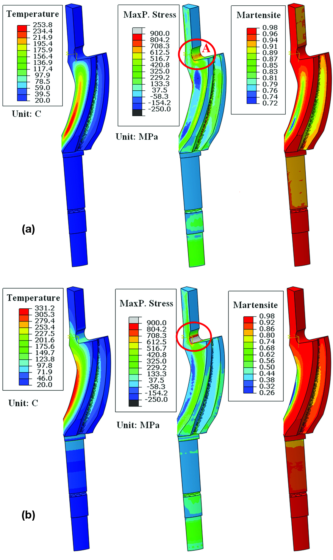
A single-chamber system is modeled to intensively quench the pinion gear. The quenching system and fixture are designed to flexibly control the water flow rates along the OD and ID surfaces. Three different quenching processes are modeled to investigate the effect of quenching process and cracking possibility. The first model has a high cooling rate on both the OD and ID surfaces. As shown in Figure 13(a), the highest stress of 570 MPa is observed at the fillet region A at 11.4 seconds during the quench; this stress is judged to not be high enough to cause cracking. However, a high quench rate on the ID surface tends to reduce the favorable residual stresses in the carburized gear tooth surface. To maximize the compressive residual stress in the gear tooth surface, a model the ID surface is insulated, and a low quench rate (low for IQ but high for conventional quenching) is applied on the OD surface. At 27.2 seconds during the quench, a high tensile stress of 1000 MPa is predicted at location A as shown in Figure 13(b); this stress indicates a high cracking possibility. The delayed martensite transformation in the tooth ID surface tends to expand the whole tooth section, which creates a bending effect on the region A. Contrary to the traditional thinking, the tensile stress in fillet region A is reduced by applying a high quench rate on the OD while keeping the ID surface insulated.
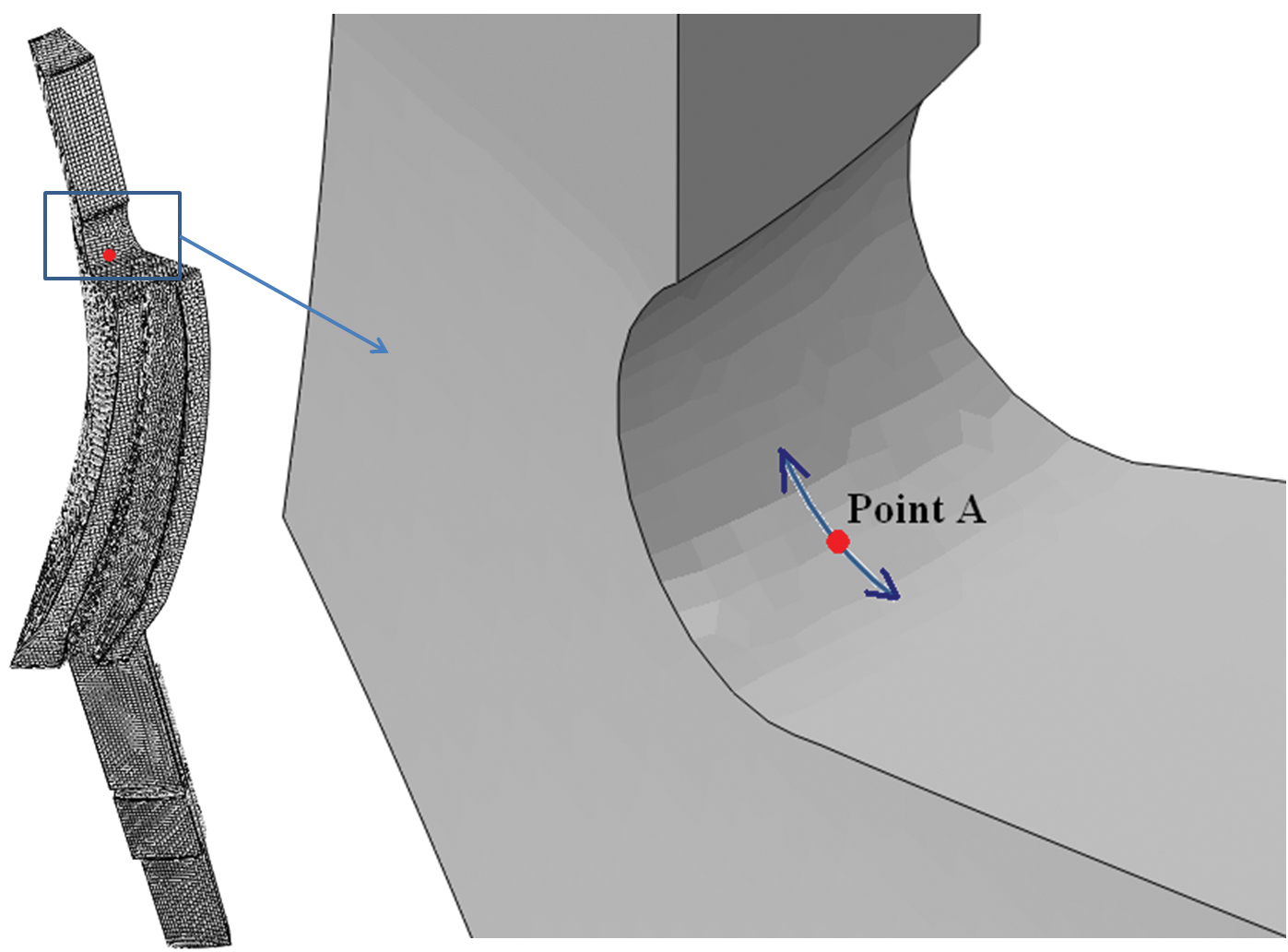
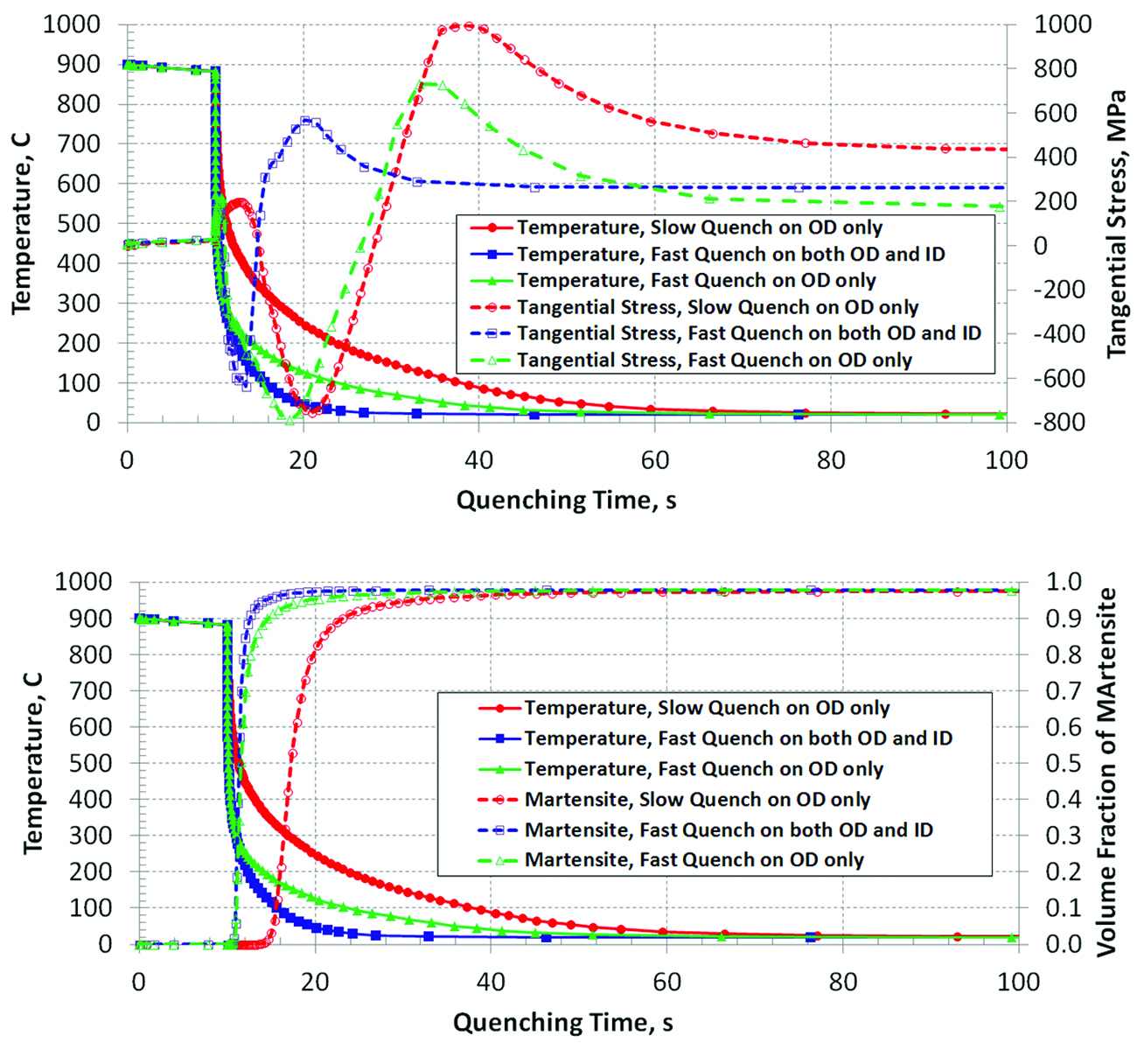
During quenching, the highest maximum principal stresses at point A are the tangential stress, as shown in Figure 14. A local cylindrical coordinate system is used to convert the stress tensor to the tangential stresses at point A during quenching. The temperature, martensite, and tangential stress at point A are plotted in terms of quenching time for all the three cases.
The transferring time between opening heating furnace and staring quenching is 10 seconds. The heat loss during air transfer will affect the gear response during quenching, so it is modeled. Figure 10 compares the tangential stresses at point A for all the three cases. Fast quenching on both ID and OD surfaces has the lowest peak stress about 570 MPa. With slow quenching on OD surface only, the stress peak is as high as 1000 MPa. By fast quenching on OD surface only, the stress peak is 700 MPa, which indicates a small cracking possibility. All the three cases end up with residual tension at the fillet region A, and lowest residual tension is predicted from the case of fast quenching OD surface only.
Summary
Accurate modeling of heat treat process provides a method for examining heat treat process steps and the complex relationships between part geometry, steel hardenability and phase transformations, stress state and part dimensional change. Specific cases were reported as examples of modeling application for real problems (Figure 15).
- Decarburization was shown to produce tensile surface stresses that can be sufficiently high to cause surface cracking during finish grinding.
- Press quenching imposes residual stress states that differ from residual stress and distortion from free quenching. Springback due to the final residual stress state can be an issue and can be overcome.
- Control of local quench rate offers a way to achieve enhanced residual stress states for performance improvement. Improper local quench rates not only can degrade part performance, they can produce defective parts.
By using modeling tools such as DANTE, it is possible to predict the evolution of both stress and metallurgical phases throughout the carburizing and quench hardening process. Highly nonlinear processes such as steel heat treatment do not obey simple rule sets and nonlinear finite element analysis allows for greater depth of understanding of process effects.
References
- D. Bammann, et al., “Development of a Carburizing and Quenching Simulation Tool: A Material Model for Carburizing Steels Undergoing Phase Transformations”, Proceedings of the second International Conference on Quenching and the Control of Distortion, 367-375, November (1996)
- Z. Li, B. Lynn Ferguson, and A. M. Freborg, “Data Needs for Modeling Heat Treatment of Steel Parts”, Proceedings of Materials Science & Technology Conference, 219-226, September (2004)
- A. M. Freborg, Z. Li, B. Lynn Ferguson, and D. Schwam, “Improving the Bending Fatigue Strength of Carburized Gears”, Proceedings of Materials Science & Technology Conference, 227-234, September (2004)
- B. Lynn Ferguson, A. Freborg, and G. Petrus, “Software Simulates Quenching”, Advanced Materials and Processes, H31-H36, August (2000)
- V. S. Sagaradze, and L. V. Malygina, “Influence of Decarburization on the Properties of Case Hardened Steel”, Ural Polytechnic Institute. Translated from Metallovedenie I Termicheskaya Obrabotka Metallov, 39-43, July(1966)
- B. Lynn Ferguson, Z. Li, A. M. Freborg, “Modeling Heat Treatment of Steel Parts”, Computational Materials Science, 274-281, 34(2005)


 general practice for CQI-9 and AMS2750E")


