


From my experience, powder metals (PM), sintering, and case hardening are three processes that could be said to be joined at the hip. More often than not, the three processes will follow in succession with one interloper; debinding or dewaxing immediately following the pressing of the powder metal into a shaped form.
For the purposes of this column, I’ll concentrate on liquid phase and solid-state diffusing sintering.
Although powder metals and sintering have been around for a one and one-half generations, at least from my observation they found their useful niche in small machines similar to early mechanical calculators and copiers and likely still do to a large extent. Prior to PM, plastics were extruded through dies and used to make the small gears and other drive components in the early office machines. Since these parts were so small, machining labor was just too expensive, so injection molding became the preferred manufacturing process. This process led to metal injection molding (MIM). I’ll discuss this process later. Of course, some parts — even though they were very small — were required to withstand considerable wear, so machining from metal was necessary.
 Over the decades engineers and manufacturing were desperate to find more uses for PM primarily due to the net shape capability they provided. However, PM has two major stumbling blocks that they continue to try and overcome:
First, the part had to be capable of being removed from a hydraulic press, therefore any component had to be fairly simple in configuration — cylindrical or some similar shape with straight sides.
Second, although extreme pressure is used to compress parts, 100 percent void free is impossible to achieve. Why? First, a binder is blended with the powder because without a binder/lube the compact has no strength when it’s removed from the press and some strength is required for the parts to hold their shape through the handling required to transport parts between processes. Since the maximum practical sintered density can vary depending on the alloy grade and application about 85 to 92 to 98 percent the binder/lube serves two purposes. It allows the part to retain its shape and reduces the friction when extracting high density parts from the press.
Over the years there have been attempts to improve the surface density of PM parts, especially gears (teeth) to better compete with their wrought machined counterparts. However, there are two considerations when densifying gears. First, the tooth contact area must be as close to theoretical density as possible to withstand the compression and bending forces that drive-trains, especially automotive, must endure. Second, PM parts have notorious fatigue issues due to the microscopic voids on the surface that act as stress risers in specific applications. Therefore, the densification effect must not be limited to the surface but penetrate below the tooth’s pitch line into the tooth core, which is the center point between two adjacent tooth roots. This is not easily done while retaining the critical dimension of the gear specifications.
Back to MIM. Metal injection molding, as mentioned earlier, is an adopted process from plastic injection molding, but that’s where the similarity ends. As designers looked for more efficient methods to produce gears and other more complex shapes than traditional PM processes could provide, some of them began experimenting with the MIM process about 40 years ago. MIM shares some similar characteristics as sinter HIPing, a process I’ve discussed in earlier columns.
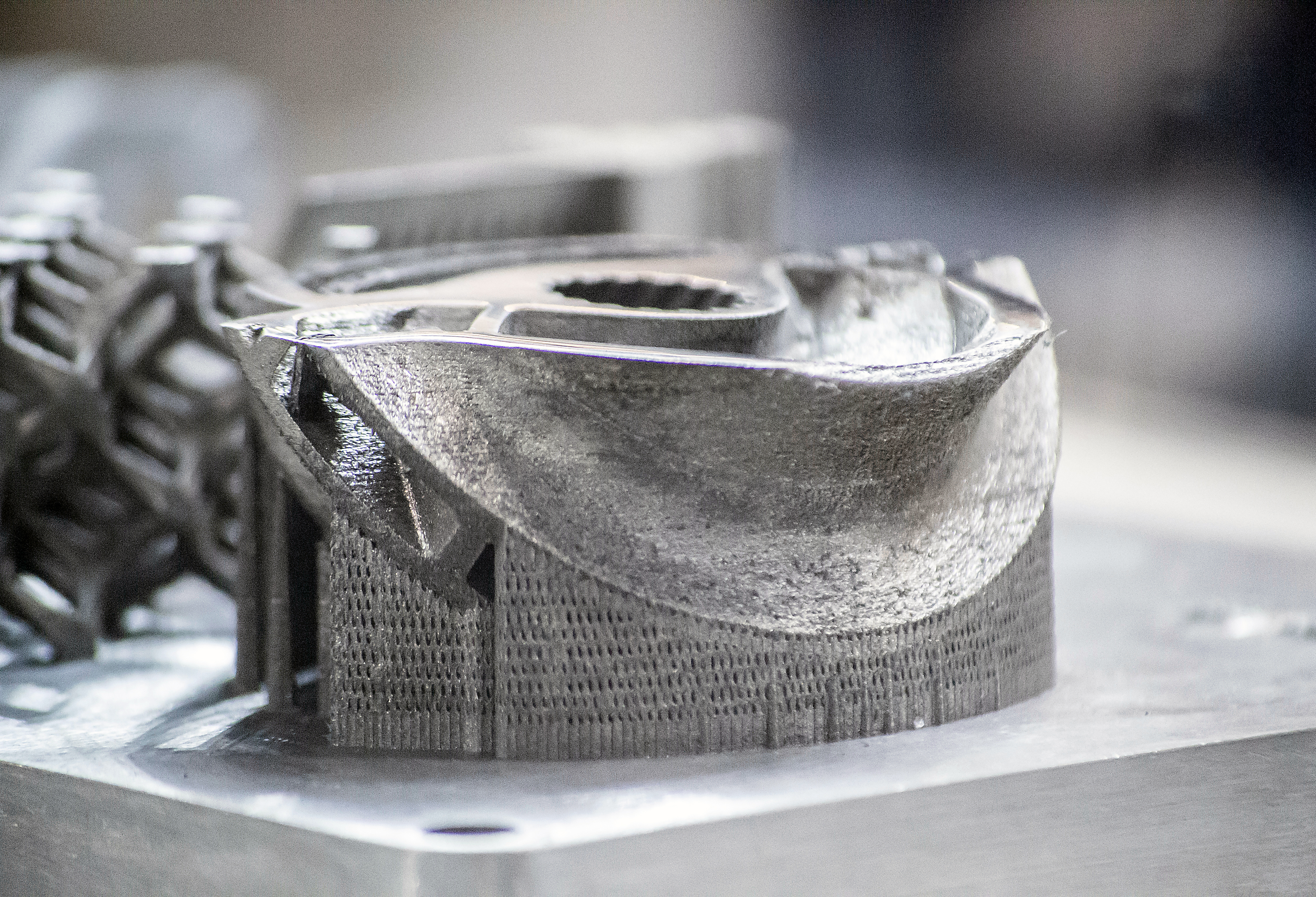
For MIM to work, the metal powder must be much finer than that for PM and the binder/lube is quite different than traditional PM. In normal PM, after the parts are pressed all of the binder/lube or as much as possible must be removed prior to sintering. In MIM, the binders consist of two materials — one to keep the part shape from sagging since by design their shapes are more complex, and a second higher temperature binder that is removed during sintering. In fact, to enable the powder to be forced to flow into the complex die designs the binder content can be up to 45 percent by volume of the part [1], Figure 1. Due to the volume of binder required, the finished product will have shrunk in volume by up to 18 percent. Over pressure sintering or sinter HIP or tungsten or silicon carbide also produces a similar shrinkage but for different reasons.
Sinter HIP is a liquid phase sintering process where cobalt acts as the secondary binder but is not removed. Special waxes provide the primary binder to keep the part from fracturing during handling. A batch operation sinter HIP goes through two hot processes; first debinding, and then high temperature sintering in the same vessel. While at temperature with all binders removed, the parts are exposed up to 60 bar pressure of argon that compresses the parts while the cobalt becomes semi liquid to fill the remaining voids in the component and results in shrinkage.
Conventional PM sintering, including MIM, relies on a solid state or diffusion bonding between powder particles; no melting takes place. Since PM and MIM have an open pour structure, MIM shrinks due to the explanation above, whereas traditional PM parts shrink only slightly if at all. Sinter HIP parts shrink because the semi-liquid cobalt flows to close the pores thereby producing a closed pore structure — thus the argon gas does not penetrate the parts, forcing the part to compress.
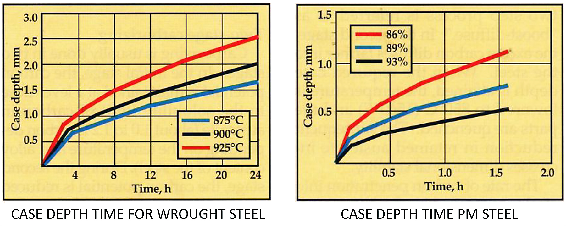
Since most of the PM parts manufactured in the U. S. contain low alloy, they have little strength after sintering. Even higher alloy powders must be heat-treated to improve hardness and strength. Since the alloy content of PM is the same throughout the cross section, they typically are neutral hardened, assuming the final hardness is appropriate for the application. However, where surface hardness is critical, carburizing is still the standard for improving wear resistance, especially in drive train components. PM parts can be carburized just as any ferrous alloy — the difference is due to the open-pore structure that allows the carburizing atmosphere to penetrate significantly faster than in fully dense wrought materials [2]. (Figure 2)
Although the open pore surface structure has advantages for carburizing, its major disadvantage is quenching. The quench fluid will enter the part surface to some depth, therefore oil is the preferred fluid. Thus, only higher alloy PM parts — unless very small — can be successfully hardened. With lower alloy PM parts where wrought material can be water or polymer quenched, low alloy PM parts will likely rust if quenched in water if not immediately heated to evaporate the water, and that’s still difficult in high-humidity conditions. Washing after oil quenching PM is also not advised. What’s the option to remove the absorbed quench oil? Tempering is conducted in gas-fired tempers that have either nitrogen atmosphere or excess air with an after burner on the effluent to burn the vaporized oil. The result can be as follows:
If the tempering temperature is too low, not all of the oil will vaporize and/or the final hardness would not be met unless temper time is extended.
Tempering too high will remove most of the oil, but the hold time will have to be adjusted to obtain the proper hardness.
References
- “Powder Injection Molding International.”
- “Carburizing P/M Parts,” by Thomas R. Prucher, BurgessNorton Mfg. Co. St. Louis, Mo.
A farewell
After writing the Hot Seat column since January 2011 until today, eight years except for 2016, I feel the time has come for me to focus on other things. Although I am retired, some may say “what retirement”? Because I just can’t sit still after working 58 years in the heat-treating and metallurgical industry. I never did consider myself a writer until Gear Solutions asked me to write a monthly column, later transitioning to Thermal Processing. “Hot Zone” and “Hot Seat” were the choices for the column titles, but I chose “Hot Seat” because I always wanted to find a way to bring more understanding of heat-treating and metallurgy to those who had an interest but couldn’t get by all of the theory being published in the trade magazines. My goal was to make it more personal, relating my own experiences in the industry, hoping to create interest from a unique perspective not usually found in technical writing without losing the technical aspects. This June column is my last. I sincerely hope I’ve made heat-treating a little more understandable.


 general practice for CQI-9 and AMS2750E")


