


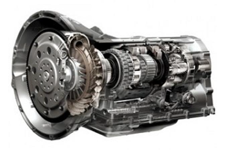
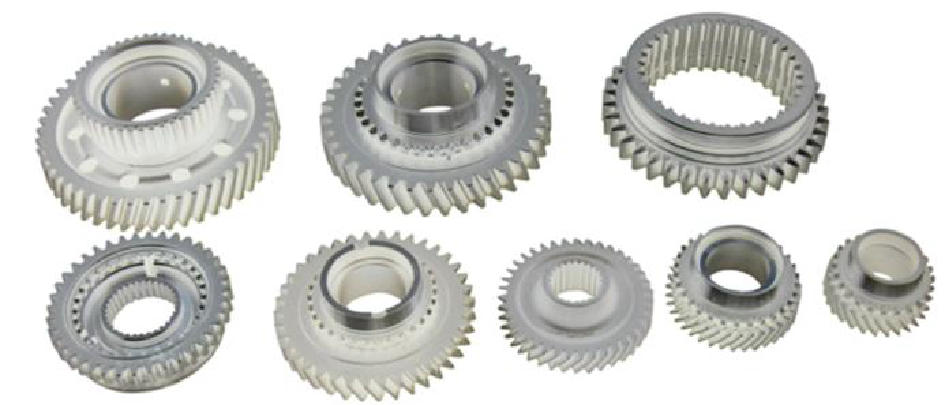
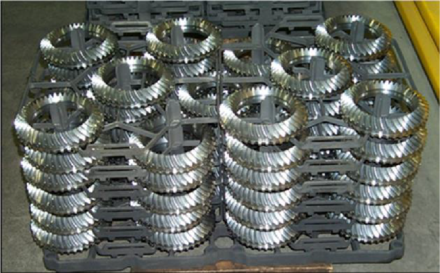
Global output of the automotive industry reached 86 million vehicles in 2014. Each vehicle is fitted with a transmission gearbox (see Figure 1). Ninety percent of these gearboxes are traditional automatic or manual, with gears being the main component (see Figure 2). Modern automatic transmissions have eight to ten steps with multiple gears for each step, as well as other parts, such as drive shafts, synchronizing rings, and bearings. Excluding stepless, constant-velocity transmissions (CVT), which comprise approximately 10 percent of the market, and adding the output increases intended for the secondary market in the coming years, global output of gears in the automotive industry is estimated to be approximately 1 billion gears per year.
While the automotive industry is the largest manufacturer of gears, it is not the only one. There are a wide variety of gears produced for other types of machines and vehicles as well. Beyond gears, there are other steel parts that will be produced, such as several hundred million drive shafts, all requiring case hardening [1].
Case Hardening of Gears
After the appropriate shape is obtained using a variety of CNC machines, each gear is case hardened to impart the right mechanical properties: hard, wear-resistant teeth and a ductile, impact- and load-bearing core. In most cases, the heat treatment used is carburizing, quenching, and tempering [2], [3]. The most common steels for carburizing are the EN 16MnCr5 or 20MnCr5 grades (AISI/SAE 5115, 5120, 8620), their equivalents, or slight modifications. Heat treating produces a typical effective case depth of 0.4–1.5 mm (0.017–0.063 inch), a surface hardness of 58–62 HRC, and a core hardness exceeding 30 HRC [4].
Deformations Resulting from Case Hardening
Typically, case hardening results in the dimensional deformation of the gear caused mainly by a change of the steel structure volume that results from austenite transformation and lack of uniformity of process parameters during the heating process, especially quenching. Distortion can also be exacerbated by non-homogeneous incoming material or by stresses created during initial machining. Distortion also depends on the geometry of the part. Since the dimensional integrity of the gear, and especially the teeth, is essential for its life, efficiency, and vibration and noise reduction, any post–heat treat distortions are corrected by relevant methods, e.g., grinding. These deformation corrections are one of the most costly processes in gear manufacturing, because it requires very high dimensional precision and requires costly working tools with material hardness of approximately 60 HRC, with as much as 0.1 mm (0.004 inch) or more material being removed [5], [6], [7], [8].
An analysis of the cost for removing quenching deformations performed in 1995 by IWT (Institut fur Werkstofftechnic) Bremen for the German industry determined the cost to be approximately 850 million euros per year in the automotive and gearbox industry and 1 billion euros per year in the bearings industry [9]. Extrapolating this data to the global industry and taking into account the 20-year production increase, the current estimated cost to correct post–heat treatment deformation is roughly 20 billion euros per year. It is a great burden for the industry and a great opportunity for savings.
Traditional Mass Production Case Hardening
Current Case Hardening Furnaces
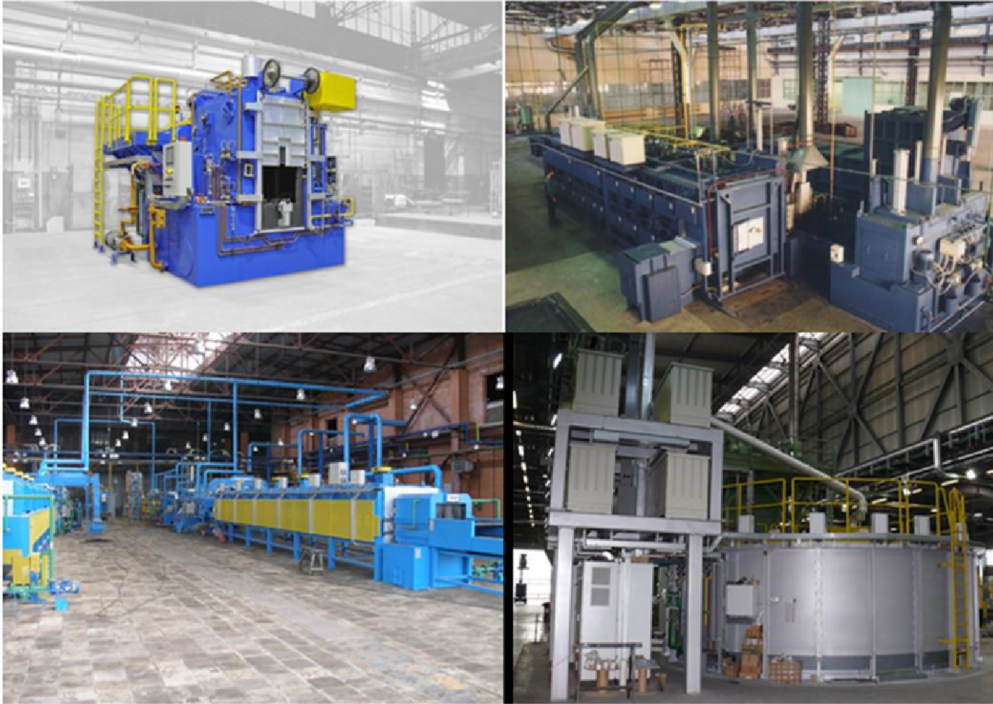
The case hardening process is usually conducted in an atmospheric furnace using an endothermic atmosphere, followed by an oil quench. These furnaces can vary in size from as small as a batch integral quench furnace capable of processing approximately 100 kg (220 lbs) gross per hour, up to continuous furnaces capable of processing much larger loads. Examples would include pusher-type furnaces — up to 500 kg/h (1,100 lbs/h), rotary hearth furnaces — up to 1,000 kg/h (2,200 lbs/h), and the largest, roller hearth furnaces with capacity exceeding 2,000 kg/h (4,400 lbs/h) (see Figure 3). These larger capacity continuous furnaces are typically used in the mass production automotive industry [10].
Carburizing in endothermic atmospheres has been known for dozens of years, and the process is properly controlled with oxygen probes and gas analyzers. However, it carries with it an inherent defect: intergranular oxidation (IGO), which is caused by the presence of oxidizing gases (CO2, H2O, and O2) in the atmosphere. Surface grinding is required to remove the dangerous IGO imperfections to the depth of as much as several dozen μm, and this removal comes at a high cost [4].
Moreover, carbon transfer in endothermic atmospheres is not especially effective (several dozen g/m3). In order to compensate for this poor transfer, large amounts of the carbon-carrying atmosphere must be supplied to the furnace — from one to over 100 m3/h, depending on the furnace size and surface to be carburized.
The overall cost of heat treating in an endothermic atmosphere is relatively high. Fuel is consumed not only to create the atmosphere, but additional fuel is consumed to bring and keep the newly introduced atmosphere up to the appropriate temperature within the furnace. Continually introducing and heating the atmosphere consumes additional energy. This, in addition to the fact that much of the atmosphere is exhausted, contributes to the system’s overall inefficiency. Endothermic atmosphere carburizing also carries with it the inherent risk of fire and explosion, and numerous costly safety procedures must be followed to mitigate the risk, not to mention the environmental issues associated with emissions [11], [12].
Quenching, which in most cases is done in oil, is an important stage of the case hardening process. Oil is a commonly used quenchant with known disadvantages arising from the three-phase nature and speed of quenching and the uncontrollability of the process. If one takes into account that each phase appears at a different time in different places on the part being quenched, large and unique deformations associated with oil quenching are obvious. Additionally, parts need to be washed after quenching in special washers where chemicals are used; these chemicals are increasingly problematic with respect to environmental regulations.
Continuous furnaces can occupy hundreds of square meters of valuable floor space. Because of the large size of these furnaces, changing the process parameters and stabilizing the working environment takes hours. Switching these furnaces on/off takes weeks. Any interruption of the production process results in huge energy and production losses.
Modern Technologies and Devices
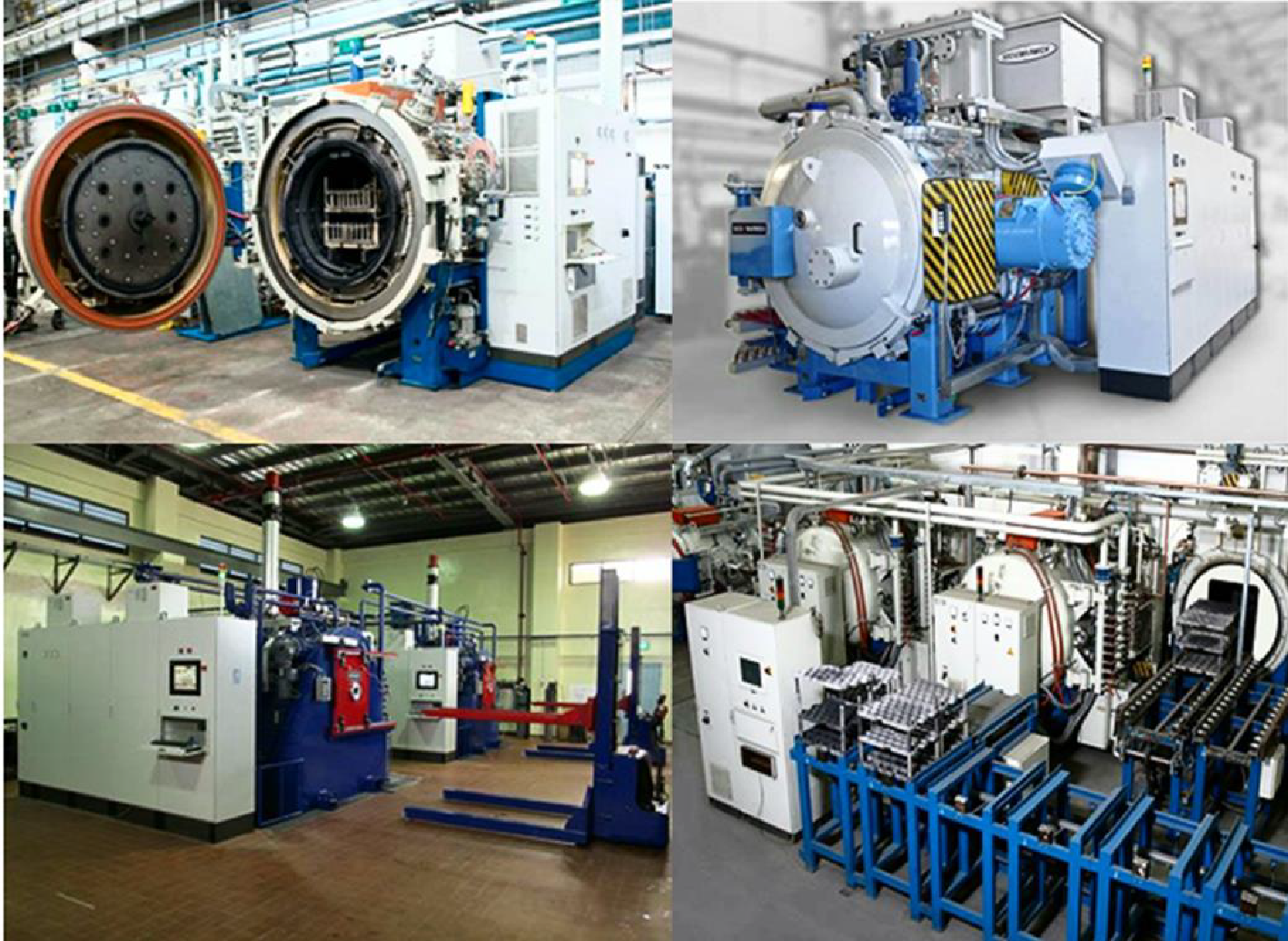
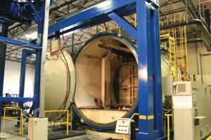
In response to the aforementioned weaknesses of traditional case hardening technologies, low-pressure carburizing (LPC) and high-pressure gas quenching (HPGQ) technologies were developed in the 1970s to 1980s. By the 1990s, the technologies had been perfected enough to find industrial applications, including mass production industries like automotive. Currently, LPC and HPGQ carried out in vacuum furnaces have effectively replaced traditional atmosphere furnaces. These new LPC/HPGQ furnaces include batch, semi-continuous, and modular systems for mass production [10] (see Figure 4).
Low-pressure carburizing overcame the weaknesses of endothermic carburizing and added a range of new possibilities. IGO was eliminated because of the total absence of oxygen in carburizing gases. Carbon transfer effectiveness increased about 20 times, considerably decreasing atmosphere consumption. Moreover, the atmosphere in the furnace is neither flammable nor explosive due to its low density. LPC is also characterized by the extraordinary capability of the atmosphere to penetrate and uniformly carburize parts with shapes, which make access difficult (blind holes) and densely packed loads. In addition, the processing temperature can be raised considerably, resulting in shortened carburizing time — as much as four to five times shorter when the temperature is raised from 920°C (1688°F) to 1040°C (1904°F) [13].
Furthermore, HPGQ significantly improved the outcome of the quenching process by decreasing the deformation rate. Gas quenching is a single-phase process and is a more uniform process with respect to a single part. Moreover, quenching rates can be regulated freely by a change of gas pressure (density) and velocity (fan rotation), thereby making the process totally controllable. Modern HPGQ systems with nitrogen or helium under 25 bar pressure are equivalent to oil quenching. As an added benefit, gas quenching eliminates the process of washing, making it a much more environmentally friendly process [14].
LPC/HPGQ vacuum furnace systems are compact, energy-efficient, and environmentally friendly devices. They are flexible, can be switched on and off at any time, and take about one hour to make production-ready. Moreover, they do not require atmosphere stabilization, and process parameters can be changed virtually instantaneously. The case hardening technology implemented in modern vacuum furnaces is a precise, efficient, clean, and environmentally friendly process [15], [16], [17], [18], [19].
Characterization of Batch Case Hardening
Although there are many benefits to these new technologies (LPC and HPGQ), there is one feature that remains unchanged. Even in new LPC/HPGQ vacuum furnace systems, parts are configured and processed in batches on special fixtures (see Figure 5) and undergo the whole case hardening process in such a configuration. This means that each part in a batch is affected by the process conditions in a unique manner based on its position within the batch. Each part is affected differently regarding the heating rate, composition of the process atmosphere, and intensity and direction of the cooling medium. There is no doubt that the parts in the outer layers of a batch are heated more quickly and to a different temperature (according to the temperature distribution within the batch), as the atmosphere around them is “richer,” and they are quenched more intensely, compared to the parts toward the center of the load. The result is that parts inside the batch have different physical and metallurgical properties than those on the outside of the batch, e.g., surface and core hardness, microstructure, and especially the effective case depth [20], [21], [22].
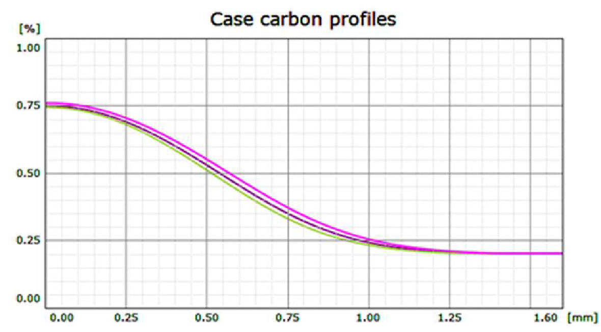
In an analysis of the effect of the carburizing temperature on the effective case depth, a typical parameter of the temperature uniformity was adopted: +/- 6°C (+/- 10°F) for a class II furnace, in accordance with AMS 2750E. Figure 6 shows the extreme carbon profiles achieved in the low-pressure carburizing process at the temperature of 950°C (1742°F) for a 0.75 mm (0.03 inch) case (for the 0.35%C criteria). The effective case depth obtained at 944°C (1731°F) was 0.72 mm (0.03 inch), whereas at 956°C (1753°F), it was 0.78 mm (0.033 inch). The difference between the effective case depths is 0.06 mm (0.003 inch), or 8 percent, for the temperature dispersion of +/- 6°C (+/- 10°F).
Similarly, the composition of the carburizing atmosphere is not uniform and changes as the atmosphere moves toward the center of the batch, with the amount of carbon decreasing gradually, resulting in poorer carburization of the parts at the center of the batch. The differences in the atmosphere composition (carbon potential) can be as great as 10 percent, and the case depth can change accordingly. The cooling rate during the quenching process also affects the case depth, with a faster quench increasing the case depth and a slower quench decreasing the case depth. Non-uniformities of the cooling medium flow rate through the batch can be as high as 50 percent and can also significantly impact the case depth by several more percentage points [14].
Due to the compounding effect of these varying parameters inherent in batch processing, it is not surprising that the industry’s quality expectations are very liberal. Tolerances can be as high as 50 percent (0.6–0.9 mm or 0.025–0.038 inch) — a direct consequence of batch processing and the currently accepted tolerances of the batch processing case hardening systems.
The intensity and uniformity of parts quenched in batches is a separate issue. Intensity of quenching determines the hardness of the core and the effective case depth, and the uniformity determines the dispersion of those parameters across parts within the batch, and, more importantly, the size of quenching deformations on individual parts. Batch quenching has one important common feature. Regardless of the device or the cooling agent (liquid or gas), batch quenching is a single-direction cooling (referred to in this paper as “2D”). This means that an individual part is affected by the cooling agent, which flows in one specific direction (e.g., from top to bottom or from left to right, with the flow not necessarily linear). In consequence, the part cooling rate is different in different places on the part. Surfaces on the inflow side are cooled more intensely than those on the outflow (or obscured) side, and the difference can be very significant.
Non-uniform quenching results in temperature gradients within each part resulting in thermal stresses and a non-uniform transformation of the microstructure. This ultimately results in large deformations of the part being quenched. Quenching results are made even worse by the fact that the quenching stream within the batch is dispersed and each part is cooled differently based on its position within the batch. A critical summary of batch 2D quenching (especially oil quenching) shows that it is an uncontrolled and non-uniform process, producing great deformations within each part and little consistency within the batch.
Using gas as the quench media, compared to oil, can reduce deformations within each part due to the single-phase nature of convection cooling with gas, but all the variations within the batch still remain [23].
Batch processing also has other quality, material handling, and cost pitfalls. For example, monitoring and reporting on the case hardening process is for the entire batch and not for individual pieces within the batch. That makes it difficult, or even impossible, to introduce and implement tighter quality standards.
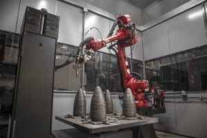
Material handling of batch loads is typically complicated and costly. Gears are produced individually. After being shaped, they are collected, packed, protected, and transported to the case hardening department (captive) or to an external firm (commercial), which can range from hundreds of meters to hundreds of kilometers away. The gears are then unpacked, washed, and racked in order to form batches on fixtures designed specifically for the case hardening process. Following an oil quench, the parts are washed again, dismantled, packed, protected, and transported back to the mechanical processing department. The whole undertaking may be divided into more than 10 operations and may take days. These material handling costs consume considerable resources, including time, materials, and money.
It is critically important to have special fixtures for case hardening, and these fixtures are typically made of heat-resisting Ni-Cr alloys. The price of a medium-sized fixture starts at thousands of euros, and the life span ranges from two to four years. Considering the fact that the largest installations require over 100 sets to ensure continuity of the production process, the cost of fixturing alone can reach hundreds of thousands of euros a year. The fixturing also affects the amount of direct energy consumption cost because it accounts for 40 to 50 percent of the overall batch weight, thereby generating higher consumption of energy needed to heat up and cool down parts.
The current technology must be appreciated for its huge productivity and minimal per-piece cost. The technology has been used and improved for decades and has been sufficiently mastered. Because of the nature of the process, the ability to further develop and improve the process has hit a wall. Specifically, the increasing needs and expectations of the industry in regard to per-piece quality improvements and reporting, repeatability, flexibility, speed, process continuity, reduction of the total costs of production, and neutrality to the environment cannot be satisfied with traditional methods.
New Approach to Case Hardening
Single-Piece Flow Case Hardening
The vast majority of weaknesses and limitations of the current case hardening processes are associated with its batch-related nature. Therefore, to eliminate these weaknesses and limitations, it would be ideal if batch processing was eliminated and replaced with a continuous, single-piece flow model. The single-piece flow concept has been around for some time in theory, in industry articles, lectures, and presentations [24], [25]. Various systems, more or less in line with the idea, have been developed, but no device for mass thermal treatment has been constructed that would fully embody the idea to date. Single-piece flow processing should mean that every single piece goes through the exact same positions and process conditions as every other piece. A system where parts are placed on trays, even in single layers, or when parts are processed individually in different process chambers, does not meet the criteria of a single-piece flow system.
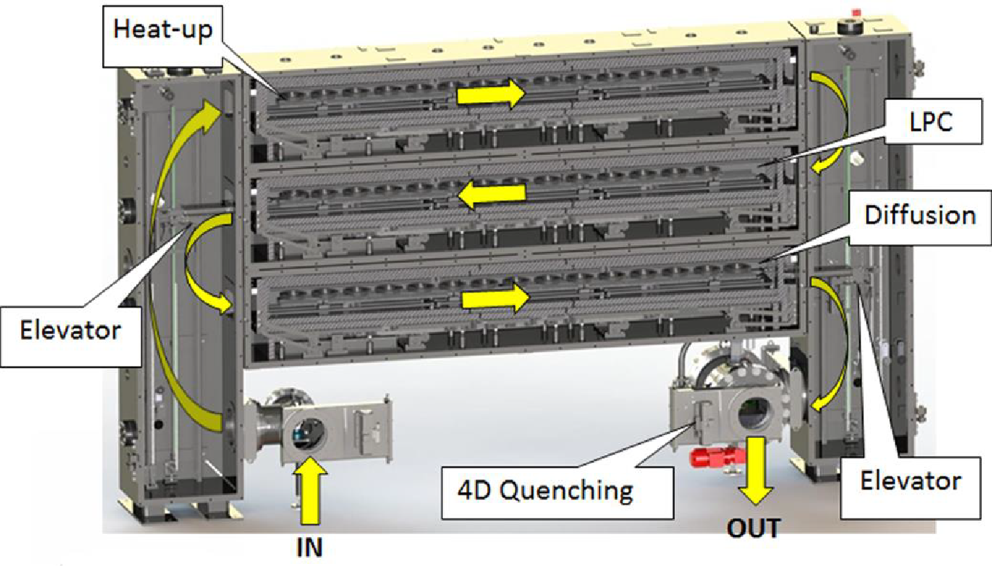
Figure 7 shows a vacuum furnace for case hardening of gears or rings using LPC and HPGQ. This system fully meets the criteria of a single-piece flow method and has all the accompanying advantages. The furnace consists of three horizontal chambers: the first one for heating up, the second for low-pressure carburizing, and the third for diffusion and pre-cooling before quenching. Additionally, a separate loading chamber and a quenching chamber (that doubles as an unloading chamber) are connected. Parts are transported between chambers by two vertical transport elevators attached to each side of the system.
The single-piece flow process runs in the following manner:
- A single gear is placed inside a loading chamber.
- It is then transported and loaded into the heating chamber.
- A walking beam mechanism indexes the gear through all the positions until the gear reaches the target carburizing temperature.
- The gear is then transported and indexed through the LPC where the surface is saturated with the right amount of carbon.
- The part is then transferred and indexed through the diffusion chamber where the desired carbon profile is achieved and the temperature is decreased before quenching.
- The gear is then transferred to the gas cooling chamber where it is quenched.
- The gear is then removed from the quenching chamber and is ready for temper.
Each gear follows in sequence and is processed the exact same way with the exact same process parameters, guaranteeing the highest level of precision and repeatability.
Precision and repeatability improve because each part runs individually and is exposed to the exact same temperature and atmosphere. Single parts heat up more quickly and uniformly due to direct radiation and the beneficial effects this direct radiation has on the more consistent conduction of heat within the gear. Moreover, any temperature gradients within the chamber are neutralized because each part goes through all the same positions. It is possible to achieve temperature uniformity as tight as +/-1°C as an average process temperature between parts. The same is true of the process atmosphere, which directly reaches the part surface consistently. Even if the atmosphere composition varies in different places within the chamber, the average value after each gear has gone through all positions is the same. Considering this, it is conceivable to achieve a uniform and repeatable carburized case depth in a single part and consistently throughout the batch of 0.6–0.7 mm (0.025–0.029 inch). This is significantly more precise than the 0.6–0.9 mm (0.025–0.038 inch) range required with today’s systems.
4D Quenching
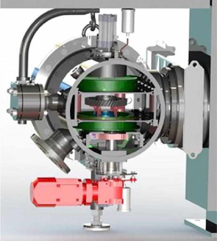
The new concept also allows for significant improvements in the quenching process, specifically the reduction of distortion. This is done primarily using a high-pressure gas quenching system installed in the quenching/unloading chamber (see Figure 8 ). The system utilizes a proprietary arrangement of cooling nozzles that surround the part and ensures a uniform flow of cooling gas from all sides: top, bottom, and side. This is referred to as “3D” cooling. In addition, a table spins the part, further enhancing quench uniformity. This spinning motion is referred to as the fourth dimension, allowing a “4D” quench of the gears for the best possible uniformity. The cooling nozzles achieve 15 bar quenching results — comparable to oil quenching — without the use of helium (He). Because the cooling nozzles can be adjusted to fit the gear’s precise size, quenching is optimized and distortion is significantly decreased. It is anticipated that, compared to oil quench systems, quenching deformation rates for each piece and across the entire batch will easily be cut in half.
Technical and Technological Assumptions
The system was designed using the following criteria for the automotive industry:
- Part diameter: 200 mm (8.0 inches)
- Weight: 3.0 kg (6.6 lbs)
- Tact time: 60 seconds
- Number of parts: 15 (in each process chamber)
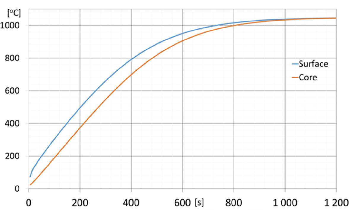

A gear with a diameter of 200 mm (8 inches) and weighing 2 kg (4.4 lbs) covers all the gears in passenger car and most truck gearboxes currently manufactured. The optimum duration of the loading-unloading cycle was 60 seconds, which corresponds well to the production cycle of CNC machine tools. An analysis of the part’s heating rate and the process of carburizing for 0.4–1.0 mm (0.02–0.04 inch) case required process chambers with 15 index positions. As a consequence, each part has a residence time of 15 minutes in each process chamber. Figure 9 shows the heating curve for a single gear, showing that the process temperature is achieved within 15 minutes. Furthermore, Figure 10 shows the processes of carburizing and diffusion at 1040°C (1904°F), where a carburized case of 0.6 mm (0.025 inch) can be obtained during 30-minute cycles. This is only one example. Other cycle durations and process temperatures can be used to obtain other required case depths.
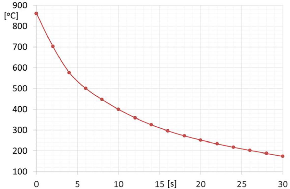
Figure 11 shows the cooling curve for a single gear in the 4D quenching chamber. The gear’s core (the hottest spot) drops below 150°C (302°F) within 40 seconds, well within the system’s 60-second tact duration.
Lean Manufacturing
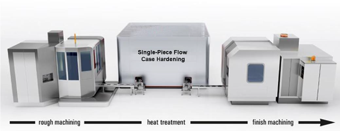
The new concept of single-piece flow case hardening is intended to be installed and operated directly on the manufacturing floor next to a CNC machine and was designed so that its footprint is similar to a CNC machine (see Figure 12). It can be installed on new production floors or at sites previously occupied by other machines, including CNC machines. A newly machined gear can be introduced into and released from the case hardening system every 30–60 seconds. The system can be completely integrated into the continuous, lean production manufacturing line, thus eliminating many, if not all, batch material handling steps.
Also, it should be noted that the system does not use fixtures for load racking. As previously mentioned, this helps reduce operating costs, including the cost to purchase and replace fixtures, as well as the consumption of energy.
Productivity
For a 200-mm (8.0-inch) diameter gear indexing 15 steps within each process chamber, a gear with an effective case depth of 0.6 mm (0.025 inch) can be produced every 60 seconds. The gear will spend 15 minutes in each chamber. This results in approximate production flows of:
- 1 gear/minute
- 60 gears/hour
- 1,400 gears/24 hours
- 10,000 gears/week
- 43,000 gears/month
Approximately 500,000 gears/year with the continuous operation mode
For gears with a smaller diameter of 100 mm (4 inches) and the same process requirements, the system can be configured for 30 positions and the tact reduced to 30 seconds in each position, resulting in annual output of approximately 1 million parts.
Conclusion
Current available case hardening technologies, both batch and continuous, fail to meet current expectations of high-volume automotive gear manufacturers in terms of quality, repeatability, flexibility, and integration of production, as well as environmental friendliness and costs, mainly because parts are arranged as batches on special fixtures for thermal treatment.
The system, developed to be a real single-piece flow case hardening system, provides potential for elimination of the shortcomings of the traditional systems and brings opportunities for significant improvements in the following areas:
- Precision and repeatability of process results
- Reduction of quenching deformations due to 4D quenching
- Integration into continuous production lines — lean manufacturing
- Flexibility and operational speed
- Individual part monitoring and reporting (as opposed to batch monitoring/reporting)
- Elimination of fixtures (cost and energy) and batch material handling logistics
- Elimination of quench oils, washers, and washing fluids
- Elimination of fire and explosion hazards
- Cleanliness of the process — less effect on the environment
All of the aforementioned advantages and opportunities are attractive for modern industry and are now currently being tested and proven in the only full-size test system that currently exists.
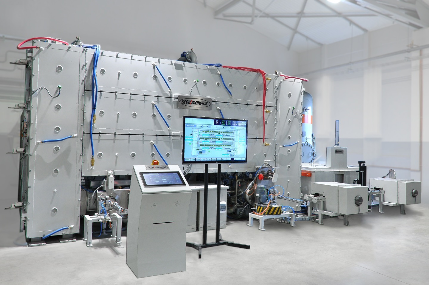
This first full-scale production system, called UniCase Master®, has already been built and installed at Seco/Warwick’s R&D center. The system consists of the main furnace for heating up, low-pressure carburizing and high-pressure gas quenching (4D quenching), and the tempering furnace (also single-piece flow) with cooling stations and manipulators. Combined together, this serves as a technologically complete, automated, and independent case hardening equipment (Figure 13).
Since the beginning of 2016, the system has successfully completed numerous technical tests and trials on real gears and rings. The technical features and reliability were proven, reaching a tact time below 60 seconds and corresponding productivity. High-temperature, low-pressure carburizing processes were researched and confirmed, achieving an effective case depth of 0.6 mm at a 60-second tact time. Due to the precise control of the case hardening process, the results, when plotted on a graph, produce almost a single line, with deviations being caused not so much by differences in the actual case profiles, but by the limitations in the hardening measuring equipment itself. In terms of hardening distortion, results after treatment in the UniCase Master® are more than optimistic — being lower, more predictable, and more repeatable than can be achieved after batch oil quenching. In many cases, distortion measurements are comparable with press quenching and are well within specified tolerances. Because of this important and consistent reduction in distortion, final hard machining can be significantly reduced and in some cases, eliminated completely.
The system is currently available for trails in order to prove its effectiveness on particular gears.
References
- Vasilash G. “The Auto Industry & Gear Making.” Modern Machine Shop, Vol. 9, 2013.
- Marinov V. “Manufacturing Technology.” 2004.
- Kohara Gear Industry Co. “Introduction to Gears.” Nakacho, 2006.
- Parrish G. “Carburizing: Microstructures and Properties.” ASM International, Materials Park, 1999.
- Krauss G. “Steels: Processing, Structure and Performance.” ASM International, Materials Park, 2005.
- Herring D. “Grain Size and its Influence on Materials Properties.” Industrial Heating, Vol. 8, 2005, 20–22.
- Herring D. “Understanding Component Failures. Part 1: Mechanisms.” Industrial Heating, Vol. 7, 2013, 16–18.
- Herring D. “Understanding Component Failures. Part 2: Analysis Methods.” Industrial Heating, Vol. 8, 2013, 18–20.
- Wulpi D. “Understanding How Components Fail.” ASM International, Materials Park, 2013.
- IWT (Institut fur Werkstofftechnic) “Economic consequences of distortion.” Bremen, 1995.
- Herring D. “Atmosphere Heat Treatment, Volume I.” BNP Media Group, 2014.
- Herring D. “Vacuum Heat Treating.” BNP Media Group, 2014.
- Chandler H. “Heat Treater’s Guide: Practices and Procedures for Irons and Steels.” ASM International, Materials Park, 1995.
- Herring D. “What Happens to Steel during Heat Treatment? Part One: Phase Transformations.” Industrial Heating, Vol. 4, 2007, 12–14. Herring D. “What Happens to Steel during Heat Treatment? Part Two: Cooling Transformations.” Industrial Heating, Vol. 6, 2007, 12–14.
- Korecki M., Kula P., Olejnik J. “New Capabilities in HPGQ Vacuum Furnaces.” Industrial Heating, Vol. 3, 2011.
- Korecki M., Olejnik J., Szczerba Z., Bazel M. “Single-chamber HPGQ Vacuum Furnace with Quenching Efficiency Comparable to Oil.” Industrial Heating, Vol. 9, 2009, 73–77.
- Herring D. “Technology Trends in Vacuum Heat Treating. Part One: Markets, Processes and Applications.” Industrial Heating, Vol. 10, 2008, 83–88.
- Herring D. “Technology Trends in Vacuum Heat Treating. Part Two: Processes and Applications.” Industrial Heating, Vol. 11, 2008, 57–62.
- Herring D. “Technology Trends in Vacuum Heat Treating. Part Three: New Technologies and Future Developments.” Industrial Heating, Vol. 1, 2009, 44–46.
- Kula P., Pietrasik R., Dybowski K., Korecki M., Olejnik J. “PreNit LPC — the Modern Technology for Automotive.” New Challenges in Heat Treatment and Surface Engineering, 2009, Dubrownik-Cavtat, Croatia, pp. 165–170.
- Korecki M., Kula P., Wołowiec E., Bazel M., Sut M. “Low Pressure Carburizing (LPC) and Low Pressure Nitriding (LPN) of Fuel Injection Nozzles made of Tool Steel.” IFHTSE 2013, Jun. 11–14, 2013. Dubrovnik-Cavtat, Croatia, 69–76.
- Korecki M., Bazel M., Sut M., Kula P., Wolowiec-Korecka E. “LPC and LPN of Tool Steel Fuel Injection Nozzles,” Industrial Heating, Vol. 6, 2014.
- Kula P., Atraszkiewicz R., Wołowiec E.: “Modern Gas Quenching Chambers supported by SimVaC Plus Hardness Application.” Industrial Processing, Vol. 3, 2008, 55–58.
- MacKenzie S.D., Li Z., Ferguson B.L. “Effect of Quenchant Flow on the Distortion of Carburized Automotive Pinion Gears.” International Federation for Heat Treatment and Surface Engineering — IFHTSE, 5th International Conference on Quenching and Control of Distortion, European Conference on Heat Treatment 2007, Berlin, 25–27 April 2007.
- MacKenzie D.S., Kumar A., Metwally H., Paingankar S., Li Z., Ferguson B.L. “Prediction of Distortion of Automotive Pinion Gears during Quenching Using CFD and FEA,” Journal of ASTM International, Vol. 6, No. 1, 2009, 1–10.
- MacKenzie D.S., Totten G.E., Gopinath N., “Quenching Fundamentals — Effect of Agitation.” Proceedings 10th Congress of the IFHT, T. Bell, and Mittemeijer, E. J., Eds., IOM Communications Ltd., London, England, 1999, 655–669.
- Heuer V., Löser K., Schmitt G., Ritter K. “One Piece Flow: Integration of Case Hardening into the Manufacturing Line.” Conf. on Gears, Oct. 4–6, 2010, TUM Garching, Germany.
- IHI “In-Line Heat Treatment — Next Generation Heat Treatment Equipment.” IHI Engineering Review, Vol. 44, No.2, 2011.


 general practice for CQI-9 and AMS2750E")


